Design and Analysis of a Permanent Magnet ... - ResearchGate
Design and Analysis of a Permanent Magnet ... - ResearchGate
Design and Analysis of a Permanent Magnet ... - ResearchGate

You also want an ePaper? Increase the reach of your titles
YUMPU automatically turns print PDFs into web optimized ePapers that Google loves.
IEEE/ASME TRANSACTIONS ON MECHATRONICS, VOL. 13, NO. 2, APRIL 2008 239<strong>Design</strong> <strong>and</strong> <strong>Analysis</strong> <strong>of</strong> a <strong>Permanent</strong> <strong>Magnet</strong>Spherical ActuatorLiang Yan, Member, IEEE, I-Ming Chen, Senior Member, IEEE, Chee Kian Lim, Guilin Yang, Member, IEEE,Wei Lin, Member, IEEE, <strong>and</strong> Kok-Meng Lee, Fellow, IEEE/ASMEAbstract—This paper has proposed a 3-DOF spherical actuatorconsisting <strong>of</strong> a ball-shaped rotor with a full circle <strong>of</strong> permanentmagnet(PM) poles <strong>and</strong> a spherical-shell-like stator with two layers<strong>of</strong> circumferential air-core coils. One key feature <strong>of</strong> this designis the parametrization <strong>of</strong> PM <strong>and</strong> coil poles. Based on the torquemodel <strong>of</strong> the PM spherical actuator, the relationship between poles’parameters <strong>and</strong> torque output can be demonstrated. As a result,the actuator design aiming at achieving maximum torque outputcan be carried out from the relationships. Another advantage <strong>of</strong>this spherical actuator is its singularity-free workspace, which isverified with the actuator torque model <strong>and</strong> condition numbers.Index Terms—Actuator design, spherical actuator, torquemodel.I. INTRODUCTIONTHE RAPID advances in robotics <strong>and</strong> automatic manufacturinghave brought about the dem<strong>and</strong> <strong>of</strong> multi-degree<strong>of</strong>-freedom(multi-DOF) actuators to replace the conventionalbulky spherical motion mechanisms that are composed <strong>of</strong> severalsingle-axis actuators. One effective option is the sphericalactuator which can achieve 2 or 3-DOF rotational motions inonly one joint. This type <strong>of</strong> actuator has the virtues <strong>of</strong> compactness,uniform motion, <strong>and</strong> nonsingularity, etc. Williams<strong>and</strong> Laithwaite et al. have done some pioneering work on thespherical induction motor [1]. This induction motor can achieve2-DOF spherical motion. Its magnetic field <strong>and</strong> torque wereanalyzed by Davey et al. [2]. A 3-DOF induction spherical motorwas conceptualized by Vachtsevanos et al. [3]. Owing tothe complexity in mechanical <strong>and</strong> winding design, it is difficultto produce a prototype. Lee et al. [4], [5] have developed avariable-reluctance spherical motor (VRSM), which has a compactsize as well as a desirable working range. A nonlineartorque model relates the current inputs to the torque output [6].<strong>Permanent</strong> magnet (PM) spherical actuators, which can achieveeither 2-DOF or 3-DOF motion, have been developed by Wanget al. [7], [8]. The rotor is entirely composed <strong>of</strong> magnetized rareearth materials <strong>and</strong> three or four coils are mounted on the stator.Chirikjian <strong>and</strong> Stein [9] have made a spherical stepper with aPM-pole rotor <strong>and</strong> a stator with an array <strong>of</strong> coils. Differencein the symmetric layout <strong>of</strong> the rotor <strong>and</strong> the stator poles allowsstepping motion in three orientations. Yang <strong>and</strong> Baek [10] proposeda 3-DOF spherical actuator composed <strong>of</strong> a rotor with twomagnet poles <strong>and</strong> a stator with five electromagnet poles. Therotor can make an arbitrary orientation <strong>and</strong> a spin. Kahlen etal. [11] developed a spherical motor consisting <strong>of</strong> a rotor with112 PM poles <strong>and</strong> a stator with 96 windings. The poles werearranged symmetrically corresponding to longitude <strong>and</strong> latitude<strong>of</strong> a globe. The actuator torque was calculated numerically. Dehezet al. [12] developed a 2-DOF spherical induction motorcomposed <strong>of</strong> a two-layer rotor with teeth surrounded by fiveinductors. The rotor can achieve unlimited angular range.In this research, a 3-DOF PM spherical actuator is proposed[13], [14]. This spherical actuator features the flexible structure,i.e., the structure <strong>of</strong> two major torque generating elements, PM<strong>and</strong> coil poles, are parameterized, which is useful for observingthe relationship between structure parameters <strong>and</strong> torque output.This provides a way to increase the actuator torque output byselecting structure dimensions. Furthermore, more PM <strong>and</strong> coilpoles could be incorporated to increase the working range aswell as the motion resolution <strong>of</strong> this spherical actuator. In thefollowing sections, the actuator torque model is derived basedon the poles’ parameters [15]. Then values <strong>of</strong> these parametersare determined based on the torque model to achieve maximumtorque output. Additionally, the singularity-free workspace <strong>of</strong>this spherical actuator is verified.Manuscript received May 11, 2007; revised November 1, 2007. Recommendedby Technical Editor M. E. Benbouzid. This work was supported bya collaborative research project under Grant U02-A-O40B for Nanyang TechnologicalUniversity, Singapore Institute <strong>of</strong> Manufacturing Technology, <strong>and</strong>Georgia Institute <strong>of</strong> Technology.L. Yan <strong>and</strong> C.-K. Lim are with the School <strong>of</strong> Mechanical <strong>and</strong> AerospaceEngineering, Nanyang Technological University, Singapore 639798, Singapore(e-mail: yanliang@pmail.ntu.edu.sg; cklim@ntu.edu.sg).I-M. Chen is with the School <strong>of</strong> Mechanical <strong>and</strong> Aerospace Engineering,Nanyang Technological University, Singapore 639798, Singapore.G. Yang <strong>and</strong> W. Lin are with Mechatronics Group, Singapore Institute <strong>of</strong>Manufacturing Technology, 71 Nanyang Drive, Singapore 638075, Singapore(e-mail: glyang@simtech.a-star.edu.sg; wlin@SIMTech.a-star.edu.sg).K.-M. Lee is with George W. Woodruff School <strong>of</strong> Mechanical Engineering,Georgia Institute <strong>of</strong> Technology, Atlanta, Georgia 30332 USA (e-mail: kokmeng.lee@me.gatech.edu).Color versions <strong>of</strong> one or more <strong>of</strong> the figures in this paper are available onlineat http://ieeexplore.ieee.org.Digital Object Identifier 10.1109/TMECH.2008.918573II. POLES GEOMETRY AND TORQUE MODELA. Working PrincipleThe working principle <strong>of</strong> this spherical actuator is illustratedin Fig. 1. This spherical actuator consists <strong>of</strong> a ball-shaped rotorwith a full circle <strong>of</strong> PM poles <strong>and</strong> a spherical-shell-like statorwith two layers <strong>of</strong> circumferential air-core coils. The rare earthPMs can generate high flux density within the actuator, <strong>and</strong> theair-core coils may simplify the torque model in a linear fashion.With pairs <strong>of</strong> coils activated in two longitudinal directions,the rotor creates tilting motions in two orthogonal directionsas shown in Fig. 1(a) <strong>and</strong> (b). By energizing the rest <strong>of</strong> thecircumferential coils, the rotor can spin about its axis. Therefore,through varying the current input <strong>of</strong> coils, the actuator1083-4435/$25.00 © 2008 IEEE
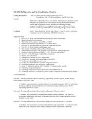
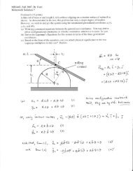
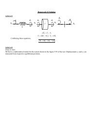
YAN et al.: DESIGN AND ANALYSIS OF A PERMANENT MAGNET SPHERICAL ACTUATOR 245Fig. 14. Support spherical rotor with transfer bearings. (a) Transfer bearing[20]. (b) Rotor support.Fig. 13.Concentricity <strong>of</strong> the stator <strong>and</strong> rotor.larger than that <strong>of</strong> the rotor (46.5 mm), so that the eddy currentinduced on the aluminum stator due to PM poles can be reducedsignificantly. Furthermore, large space between the rotor<strong>and</strong> the stator facilitates the flux density measurement inside theactuator <strong>and</strong> heat dissipation. For industrial products, the statorcan be made from nonmetal material such as Delrin or laminatedmetal materials so that stator size can be reduced about50%. Laminated ferromagnetic material not only reduces theeddy current significantly, but also improves the efficiency <strong>of</strong>the spherical actuator by “converging” the magnetic flux <strong>and</strong>reducing the magnetic energy loss.A. Concentricity <strong>of</strong> the Stator <strong>and</strong> RotorIn the assembly <strong>of</strong> the spherical actuator, it is required thatthe rotor is concentric with the stator. Two cylindrical holesseparated 90 ◦ apart are drilled at the stator equator plane, asshown in Fig. 13. Likewise, two holes that are separated 90 ◦apart <strong>and</strong> pointed to the rotor center are drilled at the rotorequator plane. Two centering pins can be inserted through theholes on the stator shell to the holes on the rotor. In this way,the concentricity <strong>of</strong> the rotor <strong>and</strong> the stator can be maintained.B. Spherical BearingTo secure the rotor position in the spherical actuator, a supportingmechanism is necessary. In the spherical actuator developedby Wang et al. [17], the spherical rotor is housed within thestator directly. Although a low friction coating was made on thestator inner surface, the sliding friction between the rotor <strong>and</strong>the stator might cause unfavorable effect on the rotor motion. Insome spherical motors [5], [9], transfer bearings or analog areused to support the rotor. A typical transfer bearing is shownin Fig. 14(a). This bearing consists <strong>of</strong> a rolling ball on the top,which can create a rolling motion with respect to the contact surface.The screw on the other end can fix the bearing on the statorfor adjusting its position. As indicated in Fig. 14(b), to supporta spherical rotor stably, at least three transfer bearings are necessary.The rolling motion <strong>of</strong> these transfer bearings producesrolling frictions lower than the sliding frictions. Nevertheless,the friction torque from the transfer bearing relative to the rotorcenter is large due to the rotor radius. The nonnegligible resultantfriction torque generated by transfer bearings may suppressthe system efficiency. The effect <strong>of</strong> friction torque on the rotorFig. 15. Implementation <strong>of</strong> spherical bearing on the rotor. (a) Spherical bearing[16]. (b) Spherical bearing at the rotor center.<strong>of</strong> the VRSM has been analyzed by Zhou [6]. To effectivelyreduce the friction, an air-bearing system has been proposed byLee et al. [18], [19]. Because the rotor floats on air, the frictionis played down significantly. However, the requirement <strong>of</strong> airsource complicates the application <strong>of</strong> this bearing system.In our spherical actuator, a spherical bearing [Fig. 15(a)] [16]is employed to support the rotor housed in the stator. This sphericalbearing can achieve a smooth 3-DOF rotational motion. Thetilting motion range <strong>of</strong> this bearing is up to ±35 ◦ . It can be assembledat the rotor center, as shown in Fig. 15(b). Because thefriction produced by this spherical bearing is very small <strong>and</strong> themoment arm <strong>of</strong> the friction force is less than 4 mm, the frictiontorque produced by the spherical bearing is negligible. Comparedwith the air bearing, the implementation <strong>of</strong> this sphericalbearing is also easy.VI. SINGULARITY-FREE WORKSPACESingularities here are defined as orientations <strong>of</strong> the rotorwhere no torque can be generated with respect to the rotorcenter even though large currents are supplied. These singularitieshave to be strictly avoided in the design because they maycause severe malfunctions.In mathematical sense, the nonsingular orientations <strong>of</strong> thespherical actuator are the orientations that there exists at leastone set <strong>of</strong> coil currents [J 1 ,J 2 ,...,J N ] T to produce the desiredactuator torque T. This implies that the matrix Q must be afull-rank matrix for any rotor orientation within the workspace.A simple way to verify the nonsingularity <strong>of</strong> the spherical
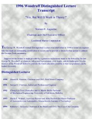
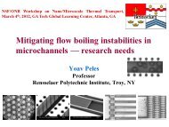
246 IEEE/ASME TRANSACTIONS ON MECHATRONICS, VOL. 13, NO. 2, APRIL 2008Fig. 16. Representation <strong>of</strong> the rotor orientation. (a) Working range <strong>of</strong> the rotor.(b) Rotation <strong>of</strong> the rotor frame.actuator is to compute the rank <strong>of</strong> torque matrix Q for everyattainable rotor orientation within the workspace. However, thismethod does not reveal how close the system is to singularitypoints. Therefore, a method based on condition number <strong>of</strong>Q is proposed. For nonsquare matrices, condition number isdefined ascond(Q) =largest singular value∣smallest singular value∣ . (19)Ideally, when cond(Q) =1, the system being evaluated is ingood condition. However, when cond(Q) ≫ 1, the system isill-conditioned or nearly singular.A. Representation <strong>of</strong> the Rotor OrientationThe workspace <strong>of</strong> the PM spherical actuator is shown inFig. 16(a). A series <strong>of</strong> PM poles are mounted along the rotorequator, whereas the air-core coils are symmetrically mountedon the stator with respect to the stator equatorial plane, with twolayers separated by an angular distance <strong>of</strong> θ s . The rotor shaftcan spin about its own z-axis, Z r ,in360 ◦ without constraint.It can also incline to an extreme position that the axes <strong>of</strong> a PMpole <strong>and</strong> the coil are aligned. Thus, the z-axis <strong>of</strong> the rotor canmove within a conical workspace with a conical angle <strong>of</strong> θ s asshown in Fig. 16(a).The orientation <strong>of</strong> the rotor frame with respect to the statorframe can be expressed by using Euler angles. Let the rotorframe be (X r ,Y r ,Z r ) <strong>and</strong> the stator frame be (X s ,Y s ,Z s ).In order to arrive at an arbitrary final orientation within theworkspace, three rotor rotations have to take place in sequence[Fig. 16(b)]. The Euler ZYZ angle expression <strong>of</strong> the rotor orientationcan be written as the multiplication <strong>of</strong> three body rotationmatrices R z (φ r ), R y (θ r ), <strong>and</strong> R z (δ r ) [21]Fig. 17.Calculation <strong>of</strong> torque matrix from rotor orientation.B. Computation <strong>of</strong> Torque Matrix Q From Rotor OrientationThe computing process <strong>of</strong> torque matrix Q from the rotororientation is carried out as follows (Fig. 17).Step 1: Computation <strong>of</strong> initial values <strong>of</strong> θ i <strong>and</strong> φ i . Becausethe positions <strong>of</strong> coil axes with respect to the rotor frame at theinitial rotor orientation are known, it is easy to obtain the initialvalues <strong>of</strong> (θ i , φ i )<strong>of</strong>theith coil, i.e.θ i,0 = π/2 − θ s /2, φ i,0 = π(i − 1)/6 (21)for coils (i =1, 2,...,12) at the upper layer, <strong>and</strong>where⎡⎣ X ⎤ ⎡sY s⎦ = R ⎣ X ⎤rY r⎦ (20)Z s Z rR = R z (φ r )R y (θ r )R z (δ r ).θ i,0 = π/2+θ s /2, φ i,0 = π(i − 13)/6 (22)for coils (i =13, 14,...,24) at the lower layer. The subscript“0” represents the initial values <strong>of</strong> θ i , φ i .Step 2: Calculation <strong>of</strong> the initial position <strong>of</strong> the coil axis.Take a unit vector starting from the rotor center along the axis<strong>of</strong> the ith coil. The Cartesian coordinates <strong>of</strong> the end point <strong>of</strong>
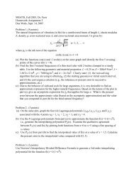
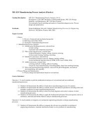
YAN et al.: DESIGN AND ANALYSIS OF A PERMANENT MAGNET SPHERICAL ACTUATOR 247this vector in the rotor frame can be calculated as⎡p i,0 = ⎣ sin θ ⎤i,0 cos φ i,0sin θ i,0 sin φ i,0⎦ . (23)cos θ i,0Step 3: Compute the final position <strong>of</strong> the end point <strong>of</strong> the unitvector after rotor rotations. The final coordinates p i <strong>of</strong> the pointp i,0 in the rotor frame can be obtained via⎡p i = ⎣ p ⎤ixp iy⎦ =[R z (φ r )R y (θ r )R z (δ r )] T p i,0p izwhere p ix , p iy , <strong>and</strong> p iz are components <strong>of</strong> p i .Step 4: Computation <strong>of</strong> trigonometric functions <strong>of</strong> (θ i , φ i ). Tocalculate the torque matrix Q, values <strong>of</strong> θ i , φ i or their trigonometricfunctions can be calculated from the final coordinates <strong>of</strong>p i . A simple way to obtain Q is to calculate θ i <strong>and</strong> φ i , thensubstitute them into the torque matrix formula. This approach iseasy to underst<strong>and</strong> <strong>and</strong> can be employed to observe the torquevariation corresponding to θ i <strong>and</strong> φ i . However, it takes longcomputation time due to the trigonometric functions in torquematrix, which may not be feasible for real-time motion control.An alternative approach is used to calculate the torque matrixQ by computing trigonometric functions <strong>of</strong> θ i <strong>and</strong> φ i from p i .Q is composed <strong>of</strong> sin θ i , cos θ i , sin φ i , <strong>and</strong> cos φ i [15]. Solvingfunctions <strong>of</strong> sin θ i , cos θ i , sin φ i , <strong>and</strong> cos φ i from the final positionp i <strong>of</strong> the axis point directly could improve the computingefficiency considerably. Specifically, trigonometric functions <strong>of</strong>θ i <strong>and</strong> φ i are calculated ascos φ i =p ix√p 2 ix + p2 iycos θ i = p iz , sin θ i =, sin φ i =p iy√p 2 ix + p2 iy√p 2 ix + p2 iy . (24)Step 5: Complete solution <strong>of</strong> the torque matrix. Repeat theaforesaid computation for all coils. A complete set <strong>of</strong> trigonometricfunctions <strong>of</strong> θ i <strong>and</strong> φ i can be calculated. By using thesevalues, the torque matrix Q can be obtained.C. Computation <strong>of</strong> Condition NumberTorque matrix Q can be calculated corresponding to rotororientations within the workspace, <strong>and</strong> thus the condition number.Repeat the computation <strong>of</strong> torque matrix by varying theangles φ r , θ r <strong>and</strong> δ r within their ranges. Based on the result,the singularity property <strong>of</strong> the PM spherical actuator workspacecan be evaluated.The variation <strong>of</strong> the condition numbers can be visualized.By fixing φ r at certain values such as 0 ◦ , 15 ◦ , 30 ◦ , etc., a 3Dplot <strong>of</strong> the condition number, denoted as n c , with respect tothe variation <strong>of</strong> θ r <strong>and</strong> δ r can be presented visually as a 2-Dsurface. By choosing different φ r , a set <strong>of</strong> 2-D surfaces canbe obtained, some <strong>of</strong> which are shown in Fig. 18. Due to thesymmetric arrangement <strong>of</strong> the PM poles about the shaft, onlythe ranges <strong>of</strong> φ r =0 ◦ –45 ◦ <strong>and</strong> δ r =0 ◦ –45 ◦ are considered.Referring to Fig. 18, we can find that the condition numbersFig. 18. Condition number <strong>of</strong> torque matrix Q (a) φ r =0 ◦ .(b)φ r =15 ◦ .(c) φ r =30 ◦ . (d) Section view for φ r =30 ◦ <strong>and</strong> δ r =0.n c do not vary too much with respect to δ r <strong>and</strong> φ r because <strong>of</strong>the evenly distributed PM poles along the rotor equator. It canalso be found that the minimum value <strong>of</strong> the condition numberis 4.877, whereas the maximum value is 5.145, which is <strong>of</strong> thesame order <strong>of</strong> magnitude 1. Therefore the workspace <strong>of</strong> this PMspherical actuator is completely singularity-free.VII. CONCLUSIONThe torque model <strong>of</strong> a PM spherical actuator consisting <strong>of</strong>a rotor with eight PM poles along the equator <strong>and</strong> a statorwith 24 coils symmetrically arranged with respect to the statorequator plane has been derived. The parametrization <strong>of</strong> PM<strong>and</strong> coil poles <strong>of</strong>fers the opportunity for the actuator design toachieve maximum torque output. Based on the theoretical analysis,a research prototype has been developed that can be employedfor future experimental investigation on magnetic field<strong>and</strong> torque variation. One significant feature <strong>of</strong> this actuator designis the singularity-free workspace, which is verified withcondition numbers <strong>of</strong> torque matrix.ACKNOWLEDGMENTThe authors would like to acknowledge the assistance fromJ. Su, Dr. W. Chen <strong>and</strong> T. S. M. Thomas.REFERENCES[1] F. C. Williams, E. R. Laithwaite, <strong>and</strong> J. Eastham, “Development <strong>and</strong> design<strong>of</strong> spherical induction motors,” Proc. Inst. ELect. Eng., pp. 471–484, Dec.1959.[2] K. Davey, G. Vachtsevanos, <strong>and</strong> R. Powers, “The analysis <strong>of</strong> fields <strong>and</strong>torques in spherical induction motors,” IEEE Trans. Magn., vol. 23, no. 1,pp. 273–282, Jan. 1987.[3] G. J. Vachtevanos, K. Davey, <strong>and</strong> K. M. Lee, “Development <strong>of</strong> a novelintelligent robotic manipulator,” IEEE Control Syst. Mag., vol. 7, no. 3,pp. 9–15, Jun. 1987.
248 IEEE/ASME TRANSACTIONS ON MECHATRONICS, VOL. 13, NO. 2, APRIL 2008[4] K. M. Lee, R. Roth, <strong>and</strong> Z. Zhou, “Dynamic modeling <strong>and</strong> control <strong>of</strong> aball-joint-like variable-reluctance spherical motor,” ASME J. Dyn. Syst.,Meas., Control, vol. 118, no. 1, pp. 29–40, Mar. 1996.[5] K. M. Lee, “Effects <strong>of</strong> fixture dynamics on back-stepping control <strong>of</strong> a VRspherical motor,” in Proc. 7th Int. Conf. Robot., Autom. Comput. Vision,2002, Singapore, pp. 1–6.[6] Z. Zhou, “Real-time control <strong>and</strong> characterization <strong>of</strong> a variable reluctancespherical motor,” Ph.D. dissertation, Georgia Inst. Technol. Atlanta, GA,May 1995.[7] J. Wang, G. W. Jewell, <strong>and</strong> D. Howe, “Spherical actuators with multipledegrees-<strong>of</strong>-freedom,” in IEE Colloq. Limited Motion Electrical ActuationSystems, vol. 494, pp. 8-1–8-6, Oct. 1998.[8] J. Wang, G. W. Jewell, <strong>and</strong> D. Howe, “A novel spherical actuator withthree degrees-<strong>of</strong>-freedom,” in IEEE Trans. Magn., vol. 34, no. 4, pp. 2078–2080, Jun. 1998.[9] G. S. Chirikjian <strong>and</strong> D. Stein, “Kinematic design <strong>and</strong> commutation <strong>of</strong> aspherical stepper motor,” IEEE/ASME Trans. Mechatron., vol. 4, no. 4,pp. 342–353, Dec. 1999.[10] C. Yang <strong>and</strong> Y. S. Baek, “<strong>Design</strong> <strong>and</strong> control <strong>of</strong> the 3 degrees <strong>of</strong> freedomactuator by controlling the electromagnetic force,” IEEE Trans. Magn.,vol. 35, no. 5, pp. 3607–3609, Sep. 1999.[11] K. Kahlen, I. Voss, C. Priebe, <strong>and</strong> R. W. De Doncker, “Torque control<strong>of</strong> a spherical machine with variable pole pitch,” IEEE Trans. PowerElectron., vol. 19, no. 6, pp. 1628–1634, Nov. 2004.[12] B. Dehez, G. Galary, <strong>and</strong> B. Raucent, “Development <strong>of</strong> a spherical inductionmotor with two degrees <strong>of</strong> freedom,” IEEE Trans. Magn., vol. 42,no. 8, pp. 2077–2088, Aug. 2006.[13] L. Yan, I. M. Chen, C. K. Lim, G. L. Yang, W. Lin, <strong>and</strong> K. M. Lee,“Experimental investigation on the magnetic field <strong>of</strong> a permanent magnetspherical actuator,” in Proc. IEEE/ASME Int. Conf. Adv. Intell. Mechatron.,California, Jul. 2005, pp. 347–352.[14] L. Yan, I. M. Chen, G. L. Yang, <strong>and</strong> K. M. Lee, “Analytical <strong>and</strong> experimentalinvestigation on the magnetic field <strong>and</strong> torque <strong>of</strong> a permanentmagnet spherical actuator,” IEEE/ASME Trans. Mechatron., vol. 11, no. 4,pp. 409–419, Aug. 2006.[15] L. Yan, I. M. Chen, C. K. Lim, G. L. Yang, W. Lin, <strong>and</strong> K. M. Lee, “Torquemodeling <strong>of</strong> a spherical actuator based on lorentz force law,” in Proc. IEEEInt. Conf. Robot. Autom., Barcelona, Spain, Apr. 2005, pp. 3657–3662.[16] Specification <strong>of</strong> transfer bearings. (2004). [Online]. Available: http://www.balltransfergroup.com.[17] J. Wang, G. W. Jewell, <strong>and</strong> D. Howe, “Modelling <strong>of</strong> a novel sphericalpermanent magnet actuator,” in Proc. 1997 IEEE Int. Conf. Robot. Autom.,Albuquerque, New Mexico, Apr. 1997, vol. 145, pp. 1190–1195.[18] K. M. Lee, D. E. Ezenekwe, <strong>and</strong> T. He, “<strong>Design</strong> <strong>and</strong> control <strong>of</strong> a sphericalair-bearing system for multi-d.o.f ball-joint-like actuators,” Mechatronics,vol. 13, pp. 175–194, 2003.[19] D. E. Ezenekwe, “<strong>Design</strong> methodology <strong>of</strong> an air bearing system for Multi-DOF spherical actuator motion control applications,” Ph.D. dissertation,Georgia Inst. Technol. Atlanta, GA, Dec. 1998.[20] Hephaist Seiko Co., Ltd. Specification <strong>of</strong> spherical bearings.[21] J. J. Craig, Introduction to Robotics: Mechanics <strong>and</strong> Control. Reading,MA: Addison-Wesley, 1989.Liang Yan (M’07) received the B. Eng. degree from North China Institute <strong>of</strong>Technology, Beijing, China, in 1995, the M. Eng. degree from Beijing Institute<strong>of</strong> Technology, Beijing, in 1998, <strong>and</strong> the Ph.D degree from Nanyang TechnologicalUniversity, Singapore, Singapore, in 2007, all in mechanical engineering.From 1998 to 2002, he was a Lecturer at Beijing Institute <strong>of</strong> Technology. Heis currently with Nanyang Technological University. His current research interestsinclude electromagnetic actuators, sensors, navigation system, <strong>and</strong> expertsystem design.Dr. Yan was the recipient <strong>of</strong> the National Defense Science <strong>and</strong> TechnologyAward, China in 2002. He is the Publication Chairman <strong>of</strong> the 2008 IEEE InternationalConference on Cybernetics <strong>and</strong> Intelligent Systems, the 2008 IEEEInternational Conference on Robotics, Automation <strong>and</strong> Mechatronics.I-Ming Chen (M’95–SM’06) received the B.S. degree from the National TaiwanUniversity, Taipei, Taiwan, R.O.C, in 1986, <strong>and</strong> the M.S. <strong>and</strong> Ph.D. degreesfrom California Institute <strong>of</strong> Technology, Pasadena, in 1989 <strong>and</strong> 1994, respectively,all in mechanical engineering.During 1999, he was a Visiting Scholar at the Japan Society for the Promotion<strong>of</strong> Science (JSPS), Kyoto University, Kyoto, Japan. During 2004, he waswith Massachusetts Institute <strong>of</strong> Technolgy (MIT), Cambridge, in 2004. Since1995, he has been with the School <strong>of</strong> Mechanical <strong>and</strong> Aerospace Engineering,Nanyang Technological University, Singapore. He is currently a Fellow <strong>of</strong>Singapore-MIT Alliance under Manufacturing Systems <strong>and</strong> Technology (MST)Program. He is also an Adjunct Pr<strong>of</strong>essor at Xian Jiao Tong University, China.His current research interests include in reconfigurable automation, biomedicalapplications <strong>of</strong> reconfigurable robotic systems, parallel kinematics machines(PKM), biomorphic underwater robots, <strong>and</strong> smart material based actuators. Heis the author or coauthor <strong>of</strong> more than 130 technical articles published in refereedinternational journals <strong>and</strong> conferences. He is currently a member <strong>of</strong> theEditorial Board for the Robotica-International Journal.Dr. Chen is currently a member <strong>of</strong> the Editorial Board for the IEEE/ AmericanSociety <strong>of</strong> Mechanical Engineers (ASME) TRANSACTIONS ON MECHATRONICS<strong>and</strong> Steering Committee <strong>of</strong> the International Federation for the Promotion <strong>of</strong>Mechanism <strong>and</strong> Machine Science (CISM)-(IFToMM) Symposium on Robot<strong>Design</strong>, Dynamics <strong>and</strong> Control (ROMANSY). He is also General Chairman <strong>of</strong>2009 IEEE/ASME International Conference on Advanced Intelligent Mechatronics(AIM2009), Singapore. He is member <strong>of</strong> ASME <strong>and</strong> the RoboCupSingapore National Committee.Chee Kian Lim received the B. Eng., M. Eng., <strong>and</strong> Ph.D. degrees in mechanicalengineering from Nanyang Technological University (NTU), Singapore, Singapore,in 1998 <strong>and</strong> 2000, respectively.During 2000–2002, he was an Assembly Product Engineer at Micron SemiconductorAsia. He is currently a Research Associate at NTU. His current researchinterests include smart actuators with special empasis on electromagnetic<strong>and</strong> ultrasonic motors, electromagnetic actuators, sensors, navigation system,<strong>and</strong> expert system design.Guilin Yang (M’02) received the B. Eng. <strong>and</strong> M. Eng. degrees from Jilin University,Changchun, China, in 1985 <strong>and</strong> 1988, respectively, <strong>and</strong> the Ph.D. degreefrom Nanyang Technological University, Singapore, in 1999, all in mechanicalengineering.During 1988, he was with the School <strong>of</strong> Mechanical Engineering, ShijiazhuangRailway Institute, China, earlier as a Lecturer, a Division Head, <strong>and</strong>then, the Vice-Dean. He is currently a Research Scientist <strong>and</strong> the Deputy GroupManager <strong>of</strong> the Mechanics Group, Singapore Institute <strong>of</strong> Manufacturing Technology,Singapore, Singapore. His current research interests include computationalkinematics, multibody dynamics, parallel-kinematics machines, modularrobots, flexure-based precision mechanisms, electromagnetic actuators, rehabilitationdevices, <strong>and</strong> industrial robot systems. He is the author or coauthor <strong>of</strong>more than 100 technical papers published in refereed international journals <strong>and</strong>conferences.Dr. Yang is a Technical Committee Member for the Robotics <strong>of</strong> InternationalFederation for the Promotion <strong>of</strong> Mechanism <strong>and</strong> Machine Science (IFToMM)<strong>and</strong> the Secretary <strong>of</strong> Singapore Chapter <strong>of</strong> IEEE Robotics <strong>and</strong> Automation Society.Wei Lin (M’03) recieved the B.Sc. degree from the University College, London,U.K. in 1985, <strong>and</strong> the M.Sc. <strong>and</strong> Ph.D. degrees from the University <strong>of</strong> Florida,Gainesville, in 1988 <strong>and</strong> 1992, respectively, all in mechanical engineering.Since 1992, he has been with Singapore Institute <strong>of</strong> Manufacturing Technology,Singapore, Singapore, where he is currently a Senior Scientist <strong>and</strong> theManager <strong>of</strong> the Mechatronics Group. He is also an Adjunct Associate Pr<strong>of</strong>essorat the National University <strong>of</strong> Singapore, Singapore, <strong>and</strong> Nanyang TechnologicalUniversity, Singapore. His current research interests include high-precisionpositioning system, micromanipulation for flexible material, <strong>and</strong> microsystemassembly.Kok-Meng Lee (M’89–SM’02–F’05) received the B.S. degree from the StateUniversity <strong>of</strong> New York, Buffalo, in 1980, <strong>and</strong> the S.M. <strong>and</strong> Ph.D. degreesfrom the Massachusetts Institute <strong>of</strong> Technology, Cambridge, in 1982 <strong>and</strong> 1985,respectively.He is a currently a Pr<strong>of</strong>essor at the Woodruff School <strong>of</strong> Mechanical Engineering,Georgia Institute <strong>of</strong> Technology, Atlanta. His current research interestsinclude system dynamics/control, robotics, automation, <strong>and</strong> mechatronics. Heholds eight patents in machine vision, three in degrees <strong>of</strong> freedom (DOF) sphericalmotor/encoder <strong>and</strong> live-bird h<strong>and</strong>ling system.Dr. Lee is a Fellow <strong>of</strong> the American Society <strong>of</strong> Mechanical Engineers(ASME). He was the recipient <strong>of</strong> the National Science Foundation (NSF) PresidentialYoung Investigator, Sigma Xi Junior Faculty Research, InternationalHall <strong>of</strong> Fame New Technology, <strong>and</strong> Kayamori Best Paper Awards.