Hitachi 2SK1056, 2SK1057, 2SK1058 Datasheet - DIY Audio Projects
Hitachi 2SK1056, 2SK1057, 2SK1058 Datasheet - DIY Audio Projects
Hitachi 2SK1056, 2SK1057, 2SK1058 Datasheet - DIY Audio Projects
- No tags were found...

You also want an ePaper? Increase the reach of your titles
YUMPU automatically turns print PDFs into web optimized ePapers that Google loves.
123<strong>2SK1056</strong>, <strong>2SK1057</strong>, <strong>2SK1058</strong>OutlineTO-3PDGS1. Gate2. Source(Flange)3. DrainAbsolute Maximum Ratings (Ta = 25°C)Item Symbol Ratings UnitDrain to source voltage <strong>2SK1056</strong> V DSX 120 V<strong>2SK1057</strong> 140<strong>2SK1058</strong> 160Gate to source voltage V GSS ±15 VDrain current I D 7 ABody to drain diode reverse drain current I DR 7 AChannel dissipation Pch* 1 100 WChannel temperature Tch 150 °CStorage temperature Tstg –55 to +150 °CNote: 1. Value at T C = 25°C2
<strong>2SK1056</strong>, <strong>2SK1057</strong>, <strong>2SK1058</strong>Channel Dissipation Pch (W)150100500Power vs. Temperature Derating50 100Case Temperature T C (°C)150Drain Current I D (A)2010521.0Maximum Safe Operation AreaI D max (Continuous)PW = 10 ms 1 shotDC Operation (T C = 25°C)PW = 100 ms 1 shotPW = 1 s 1 shotTa = 25°C0.5<strong>2SK1056</strong> <strong>2SK1057</strong><strong>2SK1058</strong>0.25 10 20 50 100 200 500Drain to Source Voltage V DS (V)10Typical Output Characteristics1.0Typical Transfer CharacteristicsDrain Current I D (A)86420V GS = 10 V T C = 25°C987654Pch = 100 W21010 20 30 40 50Drain to Source Voltage V DS (V)3Drain Current I D (A)0.80.60.40.2V DS = 10 V25T C = –25°C750 0.4 0.8 1.2 1.6 2.0Gate to Source Voltage V GS (V)4
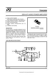
<strong>2SK1056</strong>, <strong>2SK1057</strong>, <strong>2SK1058</strong>Drain to Source Saturation VoltageV DS (on) (V)10521.00.50.20.10.1V GD = 0Drain to Source SaturationVoltage vs. Drain Current25°C 75°CT C = –25°C0.2 0.5 1.0 2 5Drain Current I D (A)10Drain to Source Voltage V DS (V)108642Drain to Source Voltage vs.Gate to Source VoltageT C = 25°C5A2AI D = 1 A0 2 4 6 8 10Gate to Source Voltage V GS (V)Input Capacitance Ciss (pF)1000500200100Input Capacitance vs. GateSource VoltageV DS = 10 Vf = 1 MHz0 –2 –4 –6 –8 –10Gate to Source Voltage V GS (V)Forward Transfer Admittance ⏐ yfs ⏐ (S)3.01.00.30.10.030.01Forward Transfer Admittancevs. FrequencyT C = 25°CV DS = 10 VI D = 2 A0.00310 k 30 k 100 k 300 k 1 M 3 M 10 MFrequency f (Hz)5
<strong>2SK1056</strong>, <strong>2SK1057</strong>, <strong>2SK1058</strong>500Switching Time vs. Drain CurrentSwitching Time ton,toff (ns)200100502010t ont off50.1 0.2 0.5 1.0 2 5 10Drain Current I D (A)Switching Time Test CircuitOutputR L = 2 ΩInputPW = 50µsduty ratio= 1 %50 Ω20 VInputWaveforms90 %10 %t ont offOutput10 %90 %6