EC Series, EC680-6 - Coffing Hoists, Coffing Hoist Parts
EC Series, EC680-6 - Coffing Hoists, Coffing Hoist Parts
EC Series, EC680-6 - Coffing Hoists, Coffing Hoist Parts
- No tags were found...
Create successful ePaper yourself
Turn your PDF publications into a flip-book with our unique Google optimized e-Paper software.
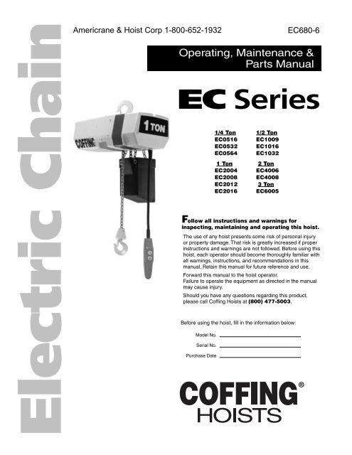
Electric Chain<strong>EC</strong>680-6Operating, Maintenance &<strong>Parts</strong> Manual<strong>EC</strong> <strong>Series</strong>Follow all instructions and warnings forinspecting, maintaining and operating this hoist.The use of any hoist presents some risk of personal injuryor property damage. That risk is greatly increased if properinstructions and warnings are not followed. Before using thishoist, each operator should become thoroughly familiar withall warnings, instructions, and recommendations in thismanual. Retain this manual for future reference and use.Forward this manual to the hoist operator.Failure to operate the equipment as directed in the manualmay cause injury.Should you have any questions regarding this product,please call <strong>Coffing</strong> <strong><strong>Hoist</strong>s</strong> at (800) 477-5003.Before using the hoist, fill in the information below:Model No.Serial No.Purchase Date1/4 Ton 1/2 Ton<strong>EC</strong>0516 <strong>EC</strong>1009<strong>EC</strong>0532 <strong>EC</strong>1016<strong>EC</strong>0564 <strong>EC</strong>10321 Ton 2 Ton<strong>EC</strong>2004 <strong>EC</strong>4006<strong>EC</strong>2008 <strong>EC</strong>4008<strong>EC</strong>2012 3 Ton<strong>EC</strong>2016 <strong>EC</strong>6005
Country Club RoadP.O. Box 779Wadesboro, NC 28170 USATEL: (800) 477-5003FAX: (800) 374-68532-1. Safety Notesa. Inspect the hoist for any evidence of shippingdamage or loose parts.b. The supporting structure and load attaching devicesshould have a load rating at least equal to that of thehoist.c. This hoist is not suitable for use in uncoveredoutdoor locations or areas containing explosive dust,vapors or gases.d. The installation area must provide safe operatingconditions for the operator, including sufficient roomfor the operator and other personnel to stand clear ofthe load at all times.e. In areas where slack chain hanging from the hoistmay create a hazard, use a chain container (see Figure2-2).2-2. Hanging the <strong>Hoist</strong>Hook mounted hoists can be used with a variety oftrolleys or stationary hangers. It is recommended that ahand-geared or motorized trolley be used when thepulling effort required to move the hoist exceeds 100pounds or when the application requires frequentmovement of the hoist.a. Make sure that the hook latch closes after hangingthe hoist.b. The standard top hook is restrained from rotation bya plate and two screws. The hook can be made toswivel freely by removing the plate, or can be rotated90° and fixed in that position.c. SeeFigure2-l for instructions on adjusting lugmountedplain trolleys.d. Refer to <strong>Coffing</strong> Motorized Trolley Operating andMaintenance Instructions manual for motorized trolleyinstallation instructions.2-3. Power Supply Connectiona. Disconnect power before making connections.b. Voltage supplied to the hoist should be within plus orminus 10% of the voltage specified for the hoist.<strong><strong>Hoist</strong>s</strong> are tagged at the factory with a tag indicatingthe voltage for which the hoist is wired. Standardsingle phase hoists are convertible from 115 to 230volts. Standard single speed, three phase hoists areconvertible from 460 volts to 230 volts. See the Wiringsection (paragraph 7-1) for voltage conversioninstructions.c. National Electrical Code (ANSI C1) and localelectrical codes should be consulted and properdisconnects, branch circuit protectors, and wiringprovided.d. Power cables furnished with the hoist have a greencolored ground wire which must be securely connectedS<strong>EC</strong>TION IIINSTALLATIONto the electrical system ground.e. When installing athree-phase hoist, make onlytemporary connections at the power line. Push the"UP" button and observe the direction of the hook. If itraises, the phasing is correct and permanentconnections may be made at the power line. If the loadblock lowers when the "UP" button is pushed, releasethe button immediately since the limit switches will notoperate to protect the hoist from over-travel. Reversethe red and black wires at the power line connection tocorrect the hook direction.CAUTIONDo not change connections in the hoist or thepushbutton assembly.2-4. Vent PlugA pressure relief plug (Item 24, Figure 8-2) is providedwhich will vent excess pressure from the transmissionhousing.2-5. Chain LubricationThe hoist chain should be liberally oiled before placingthe hoist into operation. For lubrication instructions,see paragraph 5-6.a.2-6. Testinga. Before placing the hoist into operation, check forproper limit switch operation. Push the "UP" buttonand verify that the hook block stops at least 2 inchesfrom the bottom of the hoist. Run the hoist down to itslower limit. At least 12 links of chain should remain onthe slack end. If either switch is not correct, adjustaccording to the procedure outlined in paragraph 5-2.NOTEThe upper and lower limit switches are factory set toprovide the maximum allowable hook travel. Thistravel adjustment should not be increased. However,the switches may be adjusted to stop the hook sooner ateither end of its travel.b. Attach a light load to the hook and check the hoistfor proper operation. The load should stop withoutnoticeable drift when the pushbutton is released.Increase the load to near rated load. The hoist shouldstill lift the load without hesitation and stop with nomore than one inch drift.2-7. Trolley InstallationFor Lug Mount and Plain Trolley configurations referto included manual part number CTA698-1.For Motorized Trolley configurations refer to includedmanual part number3
Country Club RoadP.O. Box 779Wadesboro, NC 28170 USATEL: (800) 477-5003FAX: (800) 374-6853Mounting ArmSpring Loaded PinSlot ForSmall ScrewdriverChain ContainerHex HeadCAUTIONWasher ScrewShort edge of chain containerbody must be mounted towardhoist (as shown).4
Country Club RoadP.O. Box 779Wadesboro, NC 28170 USATEL: (800) 477-5003FAX: (800) 374-6853d. Bring the hook into engagement with the load and makesure it is well seated before proceeding to lift the load.On multiple reeved hoists, be sure that the load isequalized on all supporting chains.e. Lift the load just clear of its supports and stop the hoistto check for proper brake operation.f. Avoid letting the hook or load swing excessively whilemoving a trolley suspended hoist.3-4. Overload Limiting ProtectionThis hoist is equipped with a factory-calibrated overloadlimiting clutch, which permits lifting loads within ratedcapacity and prevents lifting excessive loads which coulddamage the hoist. If the load exceeds the lifting capabilityof the overload clutch, the hoist will not lift the load, but themotor will to run as long as the "UP" button is pressed.Repeated attempts to lift an excessive load will overheat theoverload clutch and cause permanent damage to the clutch.CAUTIONThe overload limiting clutch is an emergency protectiondevice. It should not routinely be used to measure themaximum load to be lifted.4-1. GeneralA scheduled inspection routine should be established forthis hoist based upon severity of use and environmentalconditions. Some inspections should be made frequently(daily to monthly) and others periodically (monthly toyearly). It is suggested that an Inspection and MaintenanceCheck List and an Inspector's Report similar to thoseshowninFigures4-1and4-2beusedandfiledforreference.All inspections should be made by a designated inspector.Special inspections should be made after any significantrepairs or any situation causing suspicion that the hoist mayhave been damaged. Any hoist which has been removedfrom service for an extended time should receive aninspection as described under Periodic Inspections. ANSIB30.16, Safety Standard for Overhead <strong><strong>Hoist</strong>s</strong>, providesguidelines for hoist operation and inspection.CAUTIONAny unsafe condition disclosed by any inspection mustbe corrected before operation of the hoist is resumed.4-2. Frequent Inspectiona. Check pushbutton station, brake and limit switches forproper operation.b. Check hooks for deformation, chemical damage orcracks. Bent hooks or hooks damaged from chemicals,deformation, cracks or having excessive throat opening(see paragraph 4-6) should be replaced. Visibledeformation of any hook may be evidence of hoist abuseand overloading and indicates that a thorough inspection ofthe complete hoist should be made.c. Check that bottom hook swivels freely.d. Check for missing, bent or otherwise damaged hooklatches.e. Check pushbutton and power cord for cuts or otherdamage.S<strong>EC</strong>TION IVINSP<strong>EC</strong>TION4-3. Periodic InspectionThe exact period for the following inspections will dependon the anticipated severity of hoist use. Determination ofthis period should be based on the user's experience. It isrecommended that the user begin with a monthly inspectionand extend the periods to quarterly, semiannually, orannually, based on his monthly inspection experience.a. Clean hoist of any dirt or foreign material. Inspectbottom block for accumulation of debris.b. Perform all frequent inspections listed above, c.Check for loose bolts, screws and nuts.d. Check housings, load block, and other parts for wear,corrosion, cracks or distortion. Check for abnormalopenings between housing sections.e. Check motor brake for worn discs, oil contamination orexcessive clearance (see paragraph 5-3).f. Check mechanical load brake function (see Figure 4-3).g. Inspect the entire length of chain for gouges, nicks, weldspatter, corrosion, distortion and wear. See CHAININSP<strong>EC</strong>TION, paragraph 4-5.h. Inspecthooks and suspension parts for cracks, distortionor extreme wear.i. Inspect hooks for cracks using magnetic particle, dyepenetrant or other crack detecting methods.j. Check limit switch set points and reset if necessary (seeparagraph 5-2).k. Inspect all wiring for defective insulation, and check tobe sure all electrical connections are tight. Check motorreversing contactor or relay for burned contacts.1. Inspect for oil leaks. Check oil level.m. Inspect for missing or illegible capacity or warninglabels.n. Inspect the supporting structure for continued ability tosupport the hoist rated load.5
6Country Club RoadP.O. Box 779Wadesboro, NC 28170 USATEL: (800) 477-5003FAX: (800) 374-6853
Country Club RoadP.O. Box 779Wadesboro, NC 28170 USATEL: (800) 477-5003FAX: (800) 374-6853SCREWDRIVER NO. 1TRANSMISION COVERPLATE ANDARMATURE ASSEMBLYSCREWDRIVER NO. 27
Country Club RoadP.O. Box 779Wadesboro, NC 28170 USATEL: (800) 477-5003FAX: (800) 374-6853DiameterWear in TheseAreasWeldThroat Opening1328
Country Club RoadP.O. Box 779Wadesboro, NC 28170 USATEL: (800) 477-5003FAX: (800) 374-6853BFEGapAXDGXCH9
Country Club RoadP.O. Box 779Wadesboro, NC 28170 USATEL: (800) 477-5003FAX: (800) 374-6853CHAIN GUIDEPLAT<strong>EC</strong>HAIN GUIDEWELDWELDOLD CHAINC-LINKNEW CHAIN10
Country Club RoadP.O. Box 779Wadesboro, NC 28170 USATEL: (800) 477-5003FAX: (800) 374-6853POWER CORDNOTE POSITIONOF SUSPENSIONASSEMBLYPOWER CORDPOWER CORDSINGLE CHAINEND VIEWAS VIEWED FROMEND WITH SHORTEND COVERCOFFINGDOUBLE CHAINSIDE VIEWEND VIEWAS VIEWED FROMEND WITH SHORTEND COVERTRIPLE CHAINFIGURE 5-4. CHAINING AND SUSPENSION DIAGRAMS11
12Country Club RoadP.O. Box 779Wadesboro, NC 28170 USATEL: (800) 477-5003FAX: (800) 374-6853
Country Club RoadP.O. Box 779Wadesboro, NC 28170 USATEL: (800) 477-5003FAX: (800) 374-685313
Country Club RoadP.O. Box 779Wadesboro, NC 28170 USATEL: (800) 477-5003FAX: (800) 374-6853HOISTREVERSINGCONTACTORTO POWER SUPPLYGNDL1 L2 L3 H11 3 52 4 6A1A21 3 52 4 6H4A1UP DNA2X2H1 H4XFMRX1 X2XFMR CHARTH1 -COM (BLACK)H4 - 208V (RED)H4 -575V (GRAY)X1 -COM (BLUE)X2 -24V (YELLOW)115V (PINK)T1 T2 T3 C14 S1 S2 C15C14C15T1 T2 T3UP LIMITSWITCH(GOLD NUT)C20DOWN LIMITSWITCH(SILVER NUT)C21S1S2UPC20X1HOISTMOTORBRAKE SOLENOID(LINE VOLTAGE)DOWNPB STATIONFIGURE 7-1. Wiring Diagram for 208V or 575V (THREE PHASE) Single SpeedC21XFMR CHARTH1 - COM (BLACK)H2 - 230V (ORANGE)H4 - 460V (BLACK/RED)575V (GRAY)TO POWER SUPPLYGNDL1 L2 L3 H1SEE XFMR CHARTX2J2J1X2SEEXFMR CHART208V (RED)ON 230V OR 460V, INSULATEUNUSED H2 OR H4 WIRE1 3 52 4 6A1A21 3 5UP DN2 4 6A1A21 R1 R32 R2 R434A1FASTA2H1 H2 H4XFMRX1 - COM (BLUE)X1X2X2 - 24V (YELLOW)115V (PINK)S1 S2 T3HOIST REVERSINGCONTACTORC14 T13 J2 J1 C15T11 T1 T2 T12 7SPEED CONTROLRELAYT1 T2 T3 T11 T12 T13C14C15UP LIMITSWITCH(GOLD NUT)DOWN LIMITSWITCH(SILVER NUT)2-SPEEDMOTOR3-PH7C20C21S1S2UPC20X1BRAKE SOLENOID(LINE VOLTAGE)DOWNC21PB STATIONWIRING DIAGRAM208V, 230V, 460V, OR 575V - 3 PHASE1-SPEED HOIST, 2-SPEED TROLLEYDWG #: 98 EE2200-000*FIGURE 7-1. Wiring Diagram For 208V, 230V, 460V or 575V (THREE PHASE) 2-Speed14
H1 H2 H4X2X1Country Club RoadP.O. Box 779Wadesboro, NC 28170 USATEL: (800) 477-5003FAX: (800) 374-6853NOTICE: READ WIRING INSTRUCTIONS COMPLETELY BEFOR<strong>EC</strong>HANGING HOIST VOLTAGE. R<strong>EC</strong>ONN<strong>EC</strong>T ONLY WIREMARKERS SHOWN IN BOLD PRINT. (EX: H2 )SUPPLY VOLTAGE: 230 VAC SUPPLY VOLTAGE: 115 VACIMPORTANT!DUAL VOLTAGE HOISTNOTE FOR 230V.: TO CONVERT VOLTAGER<strong>EC</strong>ONN<strong>EC</strong>T LEADS H2, H4, S1, T2, T3 & 2 TOTHE TERMINAL BLOCK EXACTLY AS SHOWN BELOW.L1 L2 H1T2T3GND1 3 52 4 6T1 T5 T4A1A2C31 3 5UP DN2 4 6A1A2X2230V1C223HOISTREVERSINGCONTACTORSEEXFMR CHARTXFMRC14 C5 1 C6 C15T8H2 H4TERMINAL BLOCKS*4S12C3 C5 C656S2230V115V1C22TERMINAL BLOCKS*23T8H4 H2C34T25S1T3C5 C66S2115VTO POWER SUPPLY*C14C15T1T2T3T4MOTOR115/230V1-PHASEAUXT5 T8S1 S2BRAKE SOLENOID(115V COIL)11SINPAC SWITCH2 3 423 4CAPACITORC2* NOTEDIAGRAM IS SHOWN FOR 5 TO 32 FPMCHAIN HOIST MODELS. ON 64 FPMMODELS AND WIRE ROPE HOISTMODELS, THE LOCATIONS OF MOTORLEADS T5 & T8 ARE SWAPPED WHERESHOWN WITH AN ASTERISK ( ).*UPDOWNPB STATIONUP LIMITSWITCH(GOLD NUT)C20X1C21C20DOWN LIMITSWITCH(SILVER NUT)C21XFMR CHARTH1 - COM (BLACK)H2 - 115V (WHITE)H4 - 230V (ORANGE)X1 - COM (BLUE)X2 - 24V (YELLOW)X2 - 115V (PINK)FIGURE 7-2. WIRING DIAGRAM NO. 981EE2100-000 (115/230V, SINGLE PHASE)15
X1X2H1 H2 H4Country Club RoadP.O. Box 779Wadesboro, NC 28170 USATEL: (800) 477-5003FAX: (800) 374-6853NOTICE: READ WIRING INSTRUCTIONS COMPLETELY BEFOR<strong>EC</strong>HANGING HOIST VOLTAGE. R<strong>EC</strong>ONN<strong>EC</strong>T ONLY WIREMARKERS SHOWN IN BOLD PRINT. (EX: H2 )SUPPLY VOLTAGE: 230 VACIMPORTANT!DUAL VOLTAGE HOISTNOTE FOR 230V.: TO CONVERT VOLTAGE R<strong>EC</strong>ONN<strong>EC</strong>TLEADS T7, T8, T9, T5, T6, H4, H2, S1, S2 & T4 TO THETERMINAL BLOCK EXACTLY AS SHOWN BELOW.C2T7 T8 T9T5T61 2 3 4 5 6 7 8230VC3 C4 C5H4 H2 S1 S2 T4TERMINAL BLOCKC2T4T7T5T8T6T91 2 3 4 5 6 7 8460VC3 C4 C5H2 H4 S1 S2TERMINAL BLOCKT1 T2 T3 T4 T5 T6 T7 T8 T9MOTOR230/460VUPS1 S2DOWNBRAKE SOLENOID(230V COIL)HOIST REVERSINGCONTACTORC14C15DOWN LIMITSWITCH(SILVER NUT)C20C21XFMR CHARTC21H1 - COM (BLACK)PB STATIONH2 - 230V (ORANGE)H4 - 460V (BLACK/RED)X1 - COM (BLUE)X2 - 24V (YELLOW)X2 - 115V (PINK)T1 T2 T3C14 C5 C4 C3 C15XFMR1 3 52 4 6A1A21 3 5UP DN2 4 6A1A2SEEXFMR CHARTUP LIMITSWITCH(GOLD NUT)C20X1L1 L2 L3 H1 C2X2SUPPLY VOLTAGE: 460 VACTO POWER SUPPLYGNDFIGURE 7-2. WIRING DIAGRAM NO. 983EE2100-000(230V/ 460V, SINGLE SPEED)16
Country Club RoadP.O. Box 779Wadesboro, NC 28170 USATEL: (800) 477-5003FAX: (800) 374-6853SERIAL AND MODEL NUMBERS17
Country Club RoadP.O. Box 779Wadesboro, NC 28170 USATEL: (800) 477-5003FAX: (800) 374-68531232 Ton & Under Models 3 Ton Model Only 2 Ton & Under Models6453 Ton Model Only 2 Ton & Under Models 3 Ton Model Only7<strong>Parts</strong> List for Suspension Assemblies2 Ton & Under ModelsFigure 8-1 - Suspension AssembliesINDEX USAGE PART PARTNO. CODE NO. NAME1 F,G,H 14J25 Hook Assembly Kit, Swivel14J26Hook Assembly Kit, Rigid2 J 3JG23 Hook Assembly, Rigid(3-Ton Only)3 F,G,H 14J3 Trolley Lug Asseembly Kit Plain,Geared &Parallel Mounted Motorized Trolley4 J 50JG53 Trolley Lug Assembly(Plain orGeared Trolley Only)3-Ton Only5 F,G,H 14J4 Trolley Lug Assembly Kit, Cross MountedMotorized Trolley6 J 50JG54 Trolley Lug Assembly, (Motorized TrolleyOnly) 3-Ton Only7 F,G,H 50JG22 Multi-Purpose Lug Assembly18
Country Club RoadP.O. Box 779Wadesboro, NC 28170 USATEL: (800) 477-5003FAX: (800) 374-6853212221922720137286511299341024A & B268141125391523Figure 8-2 Basic <strong>Hoist</strong>19
Country Club RoadP.O. Box 779Wadesboro, NC 28170 USATEL: (800) 477-5003FAX: (800) 374-6853INDEX PART PART NAMENO. USEAGE NO.1 36J1 Brake Cover2 36J2 Electrical Cover3 560J4 Gasket, brake &Electrical Covers4 33J1 Sheave Housing33J2(Models <strong>EC</strong>-2012,<strong>EC</strong>2016, <strong>EC</strong>4006 &<strong>EC</strong>4008)Sheave Housing(Models <strong>EC</strong>0564 &<strong>EC</strong>1032)33J2-1 Sheave Housing(<strong>EC</strong>0516, <strong>EC</strong>0532,<strong>EC</strong>1009, <strong>EC</strong>1016,<strong>EC</strong>2004 & <strong>EC</strong>2008)J 33J19 Sheave Housing(Model <strong>EC</strong>6005)5 34JG1 Transmission Cover(includes 2 oil seals)6 E 35JG1 Transmission HousingD 35JG2 Transmission Housing7 A 951JL1 Power Cable(1/4 & 1/2 HP)A 952JL1 Power Cable(1 HP)B 953JL1 Power Cable8 A&B 940JE1 Wiring HarnessC 940JE1-36 Wiring Harness9 H2923P Screw(slotted hexhead)10 675J2B Decal, Capacity 1/2 Ton675J3B675J4B675J11Decal, Capacity 1 TonDecal, Capacity 2 TonDecal, Capacity 3 Ton11 H4002P Flat Washer12 677J2 Decal, <strong>Coffing</strong>13 H2981P Screw14 560J5 Gasket, Trans.INDEX PART PART NAMENO. USEAGE NO.15 676J2B Decal, <strong>Coffing</strong>16 A 679J1 Decal, PowerRequirements(115/230V)B 679J2 Decal, PowerRequirements(230/460V)A,B,C 679J3 Decal, PowerRequirements(230V)B&C 679J4 Decal, PowerRequirements (460V)B&C 679J5 Decal, PowerRequirements (575V)B&C 679J36 Decal, PowerRequirements (208V)20 Suspension AssemblyKit (Ref.#1,3,4 &5,Figure 8-2)21 703J1 Screw(Includedin all SuspensionAssembly Kits)22 H4086P Lock Washer(Included in allSuspension AssemblyKits)23 Pushbutton Cable(Ref. Figure 8-10A & 8-10B)24A H6293 Reducer Bushing24BSK1912-21W Pressure Relief Plug25 H2970 Screw26 S25-13 Level Plug27 F,G,H 4X1305 Latch KitJ 4X1307 Latch Kit (3Ton Only)28 JF679-1 Tag (230V-1 Phase)JF679-2JF679-3Tag (230V-3 Phase)Tag (460V-3 Phase)20
Please have the hoist model number, serial number, andpart number with description available for reference.18756 53646† Refer to the motor nameplate for part number, voltage,full load amperage, horsepower, and other motorinformation.Figure 8-3A Motor <strong>Parts</strong> (One Speed)Ref.PartNo. Description No. Qty.1 <strong>Hoist</strong> Motor (1-Speed)1/4 hp, 115/230V-1Ph 861J241B 11/2 hp, 115/230V-1Ph 861J242B 11 hp, 115/230V-1Ph 861J144B 11/4 hp, 230/460V-3Ph-60Hz 863J241B 11/2 hp, 230/460V-3Ph-60Hz 863J242B 11 hp, 230/460V-3Ph-60Hz 863J144B 11/4 hp, 575V-3Ph-60Hz 863J244B 11/2 hp, 575V-3Ph-60Hz 863J245B 11 hp, 575V-3Ph-60Hz 863J148B 11/4 hp, 208V-3Ph-60Hz 863J247B 11/2 hp, 208V-3Ph-60Hz 863J248B 1* Not available as an individual part.2Ref.PartNo. Description No. Qty.1 hp, 208V-3Ph-60Hz 863J149B 1.21 hp, 380V-3Ph-50Hz 863J241B 1.42 hp, 380V-3Ph-50Hz 863J242B 1.83 hp, 380V-3Ph-50Hz 863J144B 12 Adaptor Plate (1HP Only) *3 Stator Assembly *4 Rotor Assembly *5 End Shield *6 Bearing *7 Thru Bolt *8 #10 Spring Lockwasher *21
Please have the hoist model number, serial number, andpart number with description available for reference.81756 56364† Refer to the motor nameplate for part number, voltage,full load amperage, horsepower, and other motorinformation.Figure 8-3B Motor <strong>Parts</strong> (Two Speed)Ref.PartNo. Description No. Qty.1 <strong>Hoist</strong> Motor (2-Speed)1/4 hp, 230V-3Ph-60Hz 873J241B 11/2 hp, 230V-3Ph-60Hz 873J242B 11 hp, 230V-3Ph-60Hz 873J144B 11/4 hp, 460V-3Ph-60Hz 873J244B 11/2 hp, 460V-3Ph-60Hz 873J245B 11 hp, 460V-3Ph-60Hz 873J148B 11/4 hp, 575V-3Ph-60Hz 873J247B 11/2 hp, 575V-3Ph-60Hz 873J248B 11 hp, 575V-3Ph-60Hz 873J152B 12Ref.PartNo. Description No. Qty.1/4 hp, 208V-3Ph-60Hz 873J251B 11/2 hp, 208V-3Ph-60Hz 873J249B 11 hp, 208V-3Ph-60Hz 873J145B 12 Adaptor Plate (1HP Only) *3 Stator Assembly *4 Rotor Assembly *5 End Shield *6 Bearing *7 Thru Bolt *8 #10 Spring Lockwasher ** Not available as an individual part.22
Please have the hoist model number, serial number, andpart number with description available for reference.13211 1031110112789 56Figure 8-4A <strong>Parts</strong> List for Electrical <strong>Parts</strong> for 115/230V - 1-Phase ModelsRef Description Part Qty Ref Description Part QtyNo. No. No. No.1 Starting Switch 839J3 12 Capacitor1/4 &1/2 hp JL810-3 11 hp JL810-4 13 Panel Plate 257JG200 14 Reversing Contactor*1/4 & 1/2 hp:24V Coil 28860 1115V Coil 24799 11 hp, 1-Phase:5 Transformer*24V Coil 24791 1115V Coil 28905 1Sec.: 24V 821J412 1Sec.: 115V 821J411 196 Terminal Block 909J10 27 Terminal Block 909J14 48 End Plate 909J15 19 End Clamp 909J13 210 8-32UNC X 5/16" Screw H2751 211 #8 External-tooth Lockwasher H4158 212 Grommet H7956 213 Cable Tie H9006 4▲415 ft Power Cord Assembly115/230V, 1/4 & 1/2 hp 951JL1 1115/230V, 1 hp 952JL1 1* Coil voltage of the contactor and the secondary voltage of the transformer are the same. This is referred to as thecontrol voltage. Standard units are supplied with 24V Control.▲ Not Shown23
Please have the following information ready:-Model number-Serial number (if any)-Part description and number as shown in parts list302928115B15C12531336915A1612183312332167811102 17 12020202132025224242023142013Figure 8-5 Transmission25
26Please have the following information ready:-Model number-Serial number (if any)-Part description and number as shown in parts list
Please have the hoist model number, serial number, andpart number with description available for reference.505124522424522428232983720233427352120302118 253831192235327267274546434944464547 483 Ton Model OnlyFigure 8-6 Chaining <strong>Parts</strong>27
Please have the hoist model number, serial number, andpart number with description available for reference.* Replacement chain is sold by the foot. For single-chained models, add 2 ft to the lift for the total amount of feet.For double-chained models, double the lift and add 3 ft.28
Please have the hoist model number, serial number, andpart number with description available for reference.1210 11451693413 1481246715Figure 8-7A <strong>Parts</strong> List for Pushbutton, 1-SpeedRef.PartNo. Description No. Qty1 Pushbutton Station & Control Cable Assembly6 ft Cable Length PB2100 6 111 ft Cable Length PB2100-11 116 ft Cable Length PB2100-16 1Special Drop PBS2100-S# 12 Pushbutton Station Assembly (2 Button 1-Speed) 36900R 13 Control Cable Assembly6 ft Cable Length PBC2100-6 111 ft Cable Length PBC2100-11 116 ft Cable Length PBC2100-16 1Special Drop PBCS2100-S# 14 Enclosure 36998R 15 Gasket 36986 16 Contact Assembly (Includes items 6 & 7 when ordered) 36987 17 Button Assembly 36988 18 Grommet 36989 1* Hardware Kit 36939 1(Includes items 9 - 16)▲ Warning Tag 687K3W 1(†) Equal to cable length (pushbutton drop).(▲ ) Not shown.29
Please have the hoist model number, serial number, andpart number with description available for reference.1210 11451693413 1481246715Figure 8-7B <strong>Parts</strong> List for Pushbutton, 2-SpeedRef.PartNo. Description No. Qty1 Pushbutton Station & Control Cable Assembly6 ft Cable Length PB2200-6 111 ft Cable Length PB2200-11 116 ft Cable Length PB2200-16 1Special Drop PB2200-S# 12 Pushbutton Station Assembly (2 Button 2-Speed) 36800R 13 Control Cable Assembly6 ft Cable Length PBC2200-6 111 ft Cable Length PBC2200-11 116 ft Cable Length PBC2200-16 1Special Drop PBC2200-S# 14 Enclosure 36998 15 Gasket 36986 16 Contact Assembly (Includes items 6 & 7 when ordered) 36868 17 Button Assembly 36869 18 Grommet 36866 1* Hardware Kit 36939 1(Includes items 9 - 16)▲ Warning Tag 687K3W 1(†) Equal to cable length (pushbutton drop).(▲ ) Not shown.30
Please have the hoist model number, serial number, andpart number with description available for reference.1291132814136141053 75113Figure 8-8A <strong>Parts</strong> List for Limit Switch AssemblyRef Part Ref PartNo. 1 Limit Description Switch Assembly 918JG4 No. Qty 1 No. 8 Description Limit Switch Shaft JF117-3S No. Qty 1(Includes items 3-11)9 Limit Switch Nut (silver) SK6000-63Z 12 Limit Switch Bracket Assembly 918JG3 1(Includes items 3-6)3 Switch 815J1 24 6-32UNC X 1" Screw H1402P 410 Limit Switch Nut (gold) SK6000-63W 111 Retaining Ring H5520 112 Spring JF343-3 113 10-24UNC X 1/2" Screw H2970 25 6-32UNC Elastic Locknut H3944 46 Limit Switch Bracket JF900-3 1(Includes Item 7)7 Bushing JF531-4 131
Please have the hoist model number, serial number, andpart number with description available for reference.151214123212111710987191654520416181311<strong>Parts</strong> 8-8B <strong>Parts</strong> List for Long Lift Limit Switch <strong>Parts</strong>Ref Part Ref PartNo. Description No. Qty No. Description No. Qty1 Limit Switch Assembly 944JG6 113 6-32UNC X 1" Screw H1402P 4(Includes items 2-20)2 Post 110J14 13 8-32UNC X 1/2" Screw H1210 14 #8 External-tooth Lockwasher H4158 35 8-32UNC X 1/4" Screw 854823 36 Limit Switch Shaft & Gear 117JG2 17 Limit Switch Nut (silver) SK6000-63Z 18 Limit Switch Nut (gold) SK6000-63W 114 6-32UNC Elastic Locknut H3944 415 Mounting Plate 129J1 116 Frame and Guide Assembly 258JG7 117 End Plate 258J8 118 8-32UNC X 3/8" Screw H2741P 219 Drive Pinion 427J1 120 Retaining Ring H5520 121 10-24UNC X 3/8" Screw H2981P 29 Thrust Washer 255K16 110 Spring PB287 111 Bushing JF531-4 212 Switch 815J1 232
Please have the following information ready:-Model number-Serial number (if any)-Part description and number as shown in parts list15141314419127(1/4 & 1/2 HP MODELS)11(1 HP MODELS)571951211736162110986189Figure 8-9 Motor Brake <strong>Parts</strong>33
34Please have the following information ready:-Model number-Serial number (if any)-Part description and number as shown in parts list
Please have the following information ready:-Model number-Serial number (if any)-Part description and number as shown in parts list525262332112 42 2362712625Figure 8-10A. (1/4 Ton & 1/2 Ton Models)Figure 8-10B. (1Ton Models)17141117182113161314121614 1114189219201981522Figure 8-10C. (Double Chain Models)<strong>Parts</strong> List for Bottom Block AssembliesIndex Usage PartNo. Code No. Part Name1 F,H 3JG20S Hook & Latch Assembly2 F,H 4X1304 Latch Kit3 F JF20-2 Load Block Frame4 F JF20-3 Load Block Frame5 F JF700 Screw6 F 913JG4AS Bottom Block Assembly8 G 914JG2 Bottom Block Assembly(Models <strong>EC</strong>2004 & <strong>EC</strong>2008)G 914JG4 Bottom Block Assembly(Models <strong>EC</strong>4006 & <strong>EC</strong>4008)9 G 3KG1 Hook & Latch Assembly(Models <strong>EC</strong>4006 & <strong>EC</strong>4008)G 3KG6 Hook & Latch Assembly(Models <strong>EC</strong>2004 & <strong>EC</strong>2008)11 G 16JG7 Sheave & Bearing Assembly(Models <strong>EC</strong>2004 & <strong>EC</strong>2008)G,J 16JG6 Sheave & Bearing Assembly(Models <strong>EC</strong>4006, <strong>EC</strong>4008 &<strong>EC</strong>6005)Figure 8-10D. (Triple-Chain Models) 3 Ton OnlyIndex Usage PartNo. Code No. Part Name12 G 30J2 Frame (Models <strong>EC</strong>2004 &<strong>EC</strong>2008)G 30J4 Frame (Models <strong>EC</strong>4006 &<strong>EC</strong>4008)13 G,J 122JG3 Shaft Assembly14 G,J 255K2 Washer15 G,J H2403P Screw16 G,J H4085p Lock Washer17 G H3473P Hex NutJ H3964P Hex Nut18 J 30J20 Frame19 J 3JG14S Hook & Latch Assembly20 J 4X1307 Latch Kit21 J 18J8 Dead End Pin22 J 914JG23 Bottom Block Assembly23 H 30J14 Frame25 H S49-77 Screw26 H H4134 Lock Washer27 H 913JG3AS Bottom Block Assembly35
Please have the following information ready:-Model number-Serial number (if any)-Part description and number as shown in parts listIndex PartNo. No. Part Name1 927JG17 Chain Container Kit(20 Feet chain max.)927JG18 Chain Container Kit(25 Feet chain max.)927JG19 Chain Container Kit(35 Feet chain max.)927JG20 Chain Container Kit(50 Feet chain max.)2 927J17 Container(20 Feet chain max.)Index PartNo. No. Part Name927J18Container(25 Feet chain max.)927J19Container(35 Feet chain max.)927J20Container(50 Feet chain max.)3 267J3 Mounting Arm4 53J4 Chain Section5 H7929 Split Link6 H2349 Screw35456542Figure 8-10C. (Double Chain Models)36
Please have the following information ready:-Model number-Serial number (if any)-Part description and number as shown in parts listElectric and Air Powered <strong><strong>Hoist</strong>s</strong>The following warnings and operating practices have beentaken from American National (Safety) Standard ANSIB30.16 and are intended to avoid unsafe hoisting practiceswhich might lead to personal injury or property damage.These recommendations apply to all electric and airpowered hoists for vertical lifting service involving materialhandling of freely suspended unguided loads.WARNING: TO AVOID INJURY1. DO read ANSI B30.16 Safety Standard for Overhead<strong><strong>Hoist</strong>s</strong> and <strong>Hoist</strong> Manufacturer's Operating andMaintenance Instructions.2. DO be familiar with hoist operating controls, proceduresand warnings.3. DO make sure hook travel is in the same direction asshown on controls.4. DO make sure hoist limit switches function properly.5. DO maintain firm footing when operating hoist.6. DO make sure that load slings or other approved slingattachmentsareproperlysizedandseatedinthehooksaddle.7. DO make sure that the hook latch, if used, is closed andnot supporting any part of the load.8. DO make sure that load is free to move and will clearall obstructions.9. DO take up slack carefully, check load balance, lift afew inches and check load holding action beforecontinuing.10. DO avoid swinging of load or load hook.11. DOmakesurethatallpersonsstayclearofthesuspendedload.12. DO warn personnel of an approaching load.13. DO protect wire rope and load chain from weld spatter orother damaging contaminants.14. DO promptly report any malfunction, unusualperformance, or damage of the hoist.15. DO inspect hoist regularly, replace damaged or wornparts, and keep appropriate records of maintenance.16. DO use the hoist manufacturer's recommended partswhen repairing a hoist.17. DO use hook latches wherever possible.S<strong>EC</strong>TION IXDO'S AND DO NOT'S18. DO apply lubricant to the wire rope or load chain asrecommended by the hoist manufacturer.19. DO NOT lift more than rated load.20. DO NOT use the hoist load limiting device to measurethe load.21. DONOTusedamagedhoistorhoistthatisnetworkingcorrectly.22. DO NOT use the hoist with twisted, kinked, damagedor worn wire rope or chain.23. DO NOT lift a load unless wire rope is properly seated inits groove(s) or unless chain is properly seated inchain wheel (s) or sprocket(s).24. DO NOT use load rope or load chain as a sling or wraprope or chain around the load.25. DO NOT lift a load if any binding prevents equalloading on all supporting ropes or chains.26. DO NOT apply the load to the tip of the hook.27. DO NOT operate unless load is centered under hoist.28. DO NOT allow your attention to be diverted fromoperating the hoist.29. DO NOT operate the hoist beyond limits of load ropeor load chain travel.30. DO NOT use limit switches as routine operating stopsunless recommended. They are emergency devicesonly.31. DO NOT use hoist to lift, support or transport people.32. DO NOT lift loads over people.33. DO NOT leave a suspended load unattended unlessspecific precautions have been taken.34. DO NOT allow sharp contact between two hoists orbetween hoist and obstructions.35. DO NOT allow the rope, chain or hook to be used as aground for welding.36. DO NOT allow the rope, chain or hook to be touchedby a live welding electrode.37. DO NOT remove or obscure the warnings on the hoist.38. DO NOT adjust or repair a hoist unless qualified toperform hoist maintenance.39. DO NOT attempt to lengthen the load rope or chain orrepair damaged load rope or chain.37
®WARRANTYEvery hoist is thoroughly inspected andperformance tested prior to shipment from thefactory. If any properly installed, maintained andoperated hoist as outlined in the applicableaccompanying <strong>Coffing</strong> <strong><strong>Hoist</strong>s</strong> manual develops aperformance problem due to defective materials orworkmanship as verified by <strong>Coffing</strong> <strong><strong>Hoist</strong>s</strong>, repairor replacement of the hoist will be made to theoriginal purchaser without charge and the hoistwill be returned, transportation prepaid. Thiswarranty does not apply where deterioration iscaused by normal wear, abuse, improper orinadequate power supply, improper or inadequatemaintenance, eccentric or side loading,overloading, chemical orabrasive actions, excessive heat,unauthorized modifications or repairs, oruse of non-<strong>Coffing</strong> repair parts. EXCEPTAS STATED HEREIN, COFFINGHOISTS MAKES NO OTHER WARRANTIES,EXPRESS OR IMPLIED, INCLUDINGWARRANTIES OF MERCHANTABILITY ANDFITNESS FOR A PARTICULAR PURPOSE.<strong>Coffing</strong> <strong><strong>Hoist</strong>s</strong> • Country Club Road • P.O. Box 779 •Wadesboro, North Carolina 28170 USATel: 800.477.5003 • Fax: 800.374.6853 • 704.694.6829www.coffinghoists.com© 2006 <strong>Coffing</strong> ® <strong><strong>Hoist</strong>s</strong> Printed in USA


