UC010 Room unit for fancoil controller
UC010 Room unit for fancoil controller
UC010 Room unit for fancoil controller

Create successful ePaper yourself
Turn your PDF publications into a flip-book with our unique Google optimized e-Paper software.
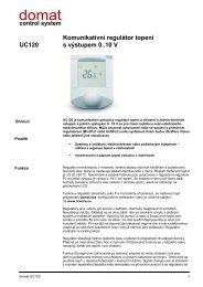
<strong>UC010</strong><strong>Room</strong> <strong>unit</strong> <strong>for</strong> <strong>fancoil</strong> <strong>controller</strong>SummaryThe <strong>UC010</strong> room <strong>unit</strong> is a communicative human-machine interface <strong>for</strong> <strong>fancoil</strong><strong>controller</strong> FC010.ApplicationFan coil systems – measurement and control of room temperatureFunctionThe <strong>unit</strong> reads room temperature, temperature correction / setpoint by a knob, andrequired operation mode which is set by a short push or in the menu. Data istransmitted to the <strong>fancoil</strong> <strong>controller</strong>. The fan coil <strong>controller</strong> may send to the <strong>unit</strong> otherdata (heating / cooling mode, fan stage, day / night / standby mode etc.) which aredisplayed on the LCD display.Units are intended <strong>for</strong> operating in a normal and chemically non-aggressiveenvironment. They do not need any servicing or maintenance. The device consists oftwo parts: bottom with screw terminal block and cover containing PCB, display, and theknob. The bottom part is fixed by 2 or 4 screws to any flat surface or a flush-mountingbox Ø 50 mm. At the back of the bottom there is an aperture <strong>for</strong> cabling. The bottomshould be installed and cabling connected first, and the upper part inserted after theconstruction works have been finished to prevent damage to the <strong>unit</strong>.Connect the room <strong>unit</strong> to FC010 over a 4 core cable, the most suitable types areJY(St)Y or LAM 2x2x0.8. Use the same type which powers the FC010 <strong>controller</strong> asif the room <strong>unit</strong> power is taken from the FC010 terminals, the cores in a terminalshould be of the same cross-section.Technical dataPower supplyConsumption24 V AC +/- 10%600 mVAMeasuring range -20 ÷ 70 °CProtectionSensor accuracySetpointCommunicationDisplayIP20according to DIN IEC 751, Class Bas configured, +/- 10 to +/- 1 KRS485 - Modbus RTULCD 60 x 60 mmdomat <strong>UC010</strong> 1
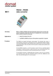
Terminals screw terminals <strong>for</strong> wires 0,14 – 1,5 mm 2CoverABS, RAL9010 (ask <strong>for</strong> other colours)Weight0,13 kgDimensionssee belowTerminalsDimensions12345671: NC not connected2: NC not connected3: K- communication, RS485 -4: K+ communication, RS485 +5: GND technical earth (TE)6: G0 power – common point7: G power07/2008 Subject to technical changes.2 domat <strong>UC010</strong>