TURBOmax VUW 282 E - Heatingspares247.com
TURBOmax VUW 282 E - Heatingspares247.com TURBOmax VUW 282 E - Heatingspares247.com
Sheet F Check operation of differential pressure switchDoes sparking startat burner?NoDoes red lockout indicator( ) glow after 10 seconds?YesIs gas solenoidactivated?Check continuity ofmicroswitch. Replaceif necessary. Checkconnection of plug X11to main switchboard.If burner still failsto light, replace mainswitchboardYesNoIs differential pressureswitch activated?NoFill and ventsystem and boilerNoHas system been filledwith water?YesCheck for dirt or damage to the differentialpressure switch, supply tubes and diaphragmYesNoYesGo to sheet HReplacemain switchboardGo to sheet G50
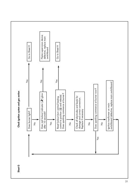
Sheet G Check ignition system and gas sectionDoes burner light?NoDoes red lockout indicator ( ) glowafter 10 seconds?YesReset lockout (turn central heatingcontrol to position ( ) and release)Does sparking commence at burner?NoCheck all electrodes and leads fordamage and correct connection.Replace if necessaryNoYesDoes sparking commence at burner now?NoIgnition tranformer on mainswitchboard defective, replace main switchboardYesNoYesGo to Sheet HFlame supervision devicedefective, replace mainswitchboardGo to Sheet H51
- Page 1 and 2: INSTRUCTIONS FOR INSTALLATION AND S
- Page 3 and 4: 1. Introduction Note: This boiler m
- Page 5 and 6: 2.2 Dimensions(All dimensions in mm
- Page 7 and 8: 3. General requirements 3.1 Related
- Page 9 and 10: 3.4.1 Flue Termination1. The termin
- Page 11 and 12: 3.7.2 Filling and make upThe system
- Page 13 and 14: 4. Boiler installationsequence4.1 G
- Page 15 and 16: 4.3.2 Using the boiler template(fig
- Page 17 and 18: 4.5.3.4 Gas supplyThe boiler is sup
- Page 19 and 20: Drill two holes 3 mm diameterthroug
- Page 21 and 22: 4.8.3 Thermostatic radiator valvesT
- Page 23 and 24: 5.4 Filling the heating systemThe b
- Page 25 and 26: At this point the preset maximumdom
- Page 27 and 28: 5.10 Functional Checks5.10.1 Introd
- Page 29 and 30: 5.14 Hand over to userSet the maxim
- Page 31 and 32: 6.2.5 Inspect burnerWith the combus
- Page 33 and 34: 7.1.3 Removal of front casing7.1.3.
- Page 35 and 36: 7.4 Replacement of burner• Isolat
- Page 37 and 38: 7.7.1 Replacement of main solenoidv
- Page 39 and 40: 7.10 Replacement oftransformer• I
- Page 41 and 42: 7.15.1 Replacement of water section
- Page 43 and 44: 7.20 Removal of printed circuitboar
- Page 45 and 46: Sheet A Check electrical supply and
- Page 47 and 48: Sheet C Check Central Heating contr
- Page 49: Sheet E Check fan/flue gas systemDo
- Page 53 and 54: Sheet J Check D.H.W. OperationDraw
- Page 55 and 56: 9.2 Wiring diagram: VUW 242 E / 282
- Page 57 and 58: 10. Short parts list Key No. Descri
- Page 59 and 60: 11. Supplementaryinformation forTUR
Sheet G Check ignition system and gas sectionDoes burner light?NoDoes red lockout indicator ( ) glowafter 10 seconds?YesReset lockout (turn central heatingcontrol to position ( ) and release)Does sparking commence at burner?NoCheck all electrodes and leads fordamage and correct connection.Replace if necessaryNoYesDoes sparking commence at burner now?NoIgnition tranformer on mainswitchboard defective, replace main switchboardYesNoYesGo to Sheet HFlame supervision devicedefective, replace mainswitchboardGo to Sheet H51


