

TURBOmax VUW 282 E - Heatingspares247.com
TURBOmax VUW 282 E - Heatingspares247.com
TURBOmax VUW 282 E - Heatingspares247.com
- No tags were found...

Create successful ePaper yourself
Turn your PDF publications into a flip-book with our unique Google optimized e-Paper software.
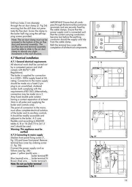
Drill two holes 3 mm diameterthrough the air duct clamp (2. Fig 24)ensuring that the drill does not penetratethe flue duct. Screw the clamp tothe boiler half ring using the self tappingscrews provided.Note: The air duct clamp must not bescrewed to the bottom of the air flueduct and terminal assembly. Theair/flue duct and terminal assemblymust be able to slide in the air ductclamp to absorb any slightmovements in the roof structure.4.7 Electrical installation4.7.1 General electrical requirementsAll electrical work shall be carried outby a competent person and shallcomply with BS7671 (IEERegulations).The boiler is supplied for connectionto a 230V~ 50Hz supply fused at 3Arating. Connection to the mains supplyshould be made via a fused 3 pinplug to an unswitched, shutteredsocket, both complying with therequirements of BS1363.(Alternatively,connection may be made via a 3Amp fused double pole isolatorhaving a contact separation of at least3mm in all poles and supplying theboiler and controls only).The point of connection to the mainsmust allow complete electrical isolationof the boiler and its ancillary controls.It should be readily accessible andadjacent to the boiler. A 3 coreflexible cord according to BS6500tables 6, 8 or 16 (3x0.75 to 3x1.5mm 2 ) should be used.Warning: This appliance must beearthed4.7.2 Connecting to mains supplySlacken front panel fixing screw (1,fig. 25) and lower front panel. Removeterminal box cover by undoing screw(1, fig. 26)Connect the power supply cord asfollows (see fig. 28):-green / yellow (earth) wire....boiler terminalBlue (neutral) wire..... boiler terminal NBrown (live) wire..... boiler terminal LNote: Do not use boiler terminalconnections 7-8-9IMPORTANT Ensure that all cordspass through the terminal box entrancegrommets and are securely fixed bythe cable clamps. Ensure that thepower supply cord is connected suchthat the current carrying conductorsbecome taut before the earthingconductor should the supply cord slipfrom the cable clamp.Refit the terminal box cover aftercompletion of all electrical componentsfig. 25GW 603/0fig. 26fig. 27GW 614/0GW 638/0-Bfig. 28GW 679/019


