TURBOmax VUW 282 E - Heatingspares247.com
TURBOmax VUW 282 E - Heatingspares247.com TURBOmax VUW 282 E - Heatingspares247.com
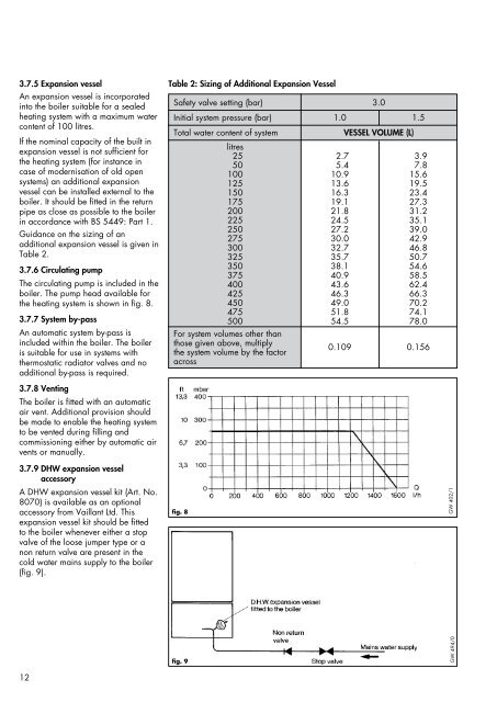
3.7.5 Expansion vesselAn expansion vessel is incorporatedinto the boiler suitable for a sealedheating system with a maximum watercontent of 100 litres.If the nominal capacity of the built inexpansion vessel is not sufficient forthe heating system (for instance incase of modernisation of old opensystems) an additional expansionvessel can be installed external to theboiler. It should be fitted in the returnpipe as close as possible to the boilerin accordance with BS 5449: Part 1.Guidance on the sizing of anadditional expansion vessel is given inTable 2.3.7.6 Circulating pumpThe circulating pump is included in theboiler. The pump head available forthe heating system is shown in fig. 8.3.7.7 System by-passAn automatic system by-pass isincluded within the boiler. The boileris suitable for use in systems withthermostatic radiator valves and noadditional by-pass is required.3.7.8 VentingThe boiler is fitted with an automaticair vent. Additional provision shouldbe made to enable the heating systemto be vented during filling andcommissioning either by automatic airvents or manually.3.7.9 DHW expansion vesselaccessoryA DHW expansion vessel kit (Art. No.8070) is available as an optionalaccessory from Vaillant Ltd. Thisexpansion vessel kit should be fittedto the boiler whenever either a stopvalve of the loose jumper type or anon return valve are present in thecold water mains supply to the boiler(fig. 9).Table 2: Sizing of Additional Expansion VesselSafety valve setting (bar) 3.0Initial system pressure (bar) 1.0 1.5Total water content of systemVESSEL VOLUME (L)litres25 2.7 3.950 5.4 7.8100 10.9 15.6125 13.6 19.5150 16.3 23.4175 19.1 27.3200 21.8 31.2225 24.5 35.1250 27.2 39.0275 30.0 42.9300 32.7 46.8325 35.7 50.7350 38.1 54.6375 40.9 58.5400 43.6 62.4425 46.3 66.3450 49.0 70.2475 51.8 74.1500 54.5 78.0For system volumes other thanthose given above, multiplythe system volume by the factoracross0.109 0.156fig. 8GW 402/112fig. 9GW 494/0
4. Boiler installationsequence4.1 GeneralThe boiler should be mounted on aflat and vertical area of wall ofsufficient area for the boiler plus therequired minimum clearances forinstallation and servicing (fig. 10).These are shown on the installationtemplate supplied with the boiler andare:5 mm either side of the boiler100 mm below the boiler*165 mm on top of the boiler500 mm in front of the boiler *** 150 mm where optional preinstallationconnecting group(Art. no. 8015) is used.** This clearance is only required toenable easier access to the boilerfor servicing and may beprovided by an openable door,etc.Note: If the boiler is to be fitted in atimber framed building, it should befitted in accordance with British Gaspublication reference DM2 'Guidefor gas installations in timber framedhousing.'4.2 Boiler deliveryThe TURBOmax is delivered in twopacks:a. the carton containing the boilerb. separately boxed flue accessory,either:• 1m horizontal flue accessory(Art. No. 300 807); or• vertical flue accessory(Art. No. 300 800)fig. 11GW 403/113
- Page 1 and 2: INSTRUCTIONS FOR INSTALLATION AND S
- Page 3 and 4: 1. Introduction Note: This boiler m
- Page 5 and 6: 2.2 Dimensions(All dimensions in mm
- Page 7 and 8: 3. General requirements 3.1 Related
- Page 9 and 10: 3.4.1 Flue Termination1. The termin
- Page 11: 3.7.2 Filling and make upThe system
- Page 15 and 16: 4.3.2 Using the boiler template(fig
- Page 17 and 18: 4.5.3.4 Gas supplyThe boiler is sup
- Page 19 and 20: Drill two holes 3 mm diameterthroug
- Page 21 and 22: 4.8.3 Thermostatic radiator valvesT
- Page 23 and 24: 5.4 Filling the heating systemThe b
- Page 25 and 26: At this point the preset maximumdom
- Page 27 and 28: 5.10 Functional Checks5.10.1 Introd
- Page 29 and 30: 5.14 Hand over to userSet the maxim
- Page 31 and 32: 6.2.5 Inspect burnerWith the combus
- Page 33 and 34: 7.1.3 Removal of front casing7.1.3.
- Page 35 and 36: 7.4 Replacement of burner• Isolat
- Page 37 and 38: 7.7.1 Replacement of main solenoidv
- Page 39 and 40: 7.10 Replacement oftransformer• I
- Page 41 and 42: 7.15.1 Replacement of water section
- Page 43 and 44: 7.20 Removal of printed circuitboar
- Page 45 and 46: Sheet A Check electrical supply and
- Page 47 and 48: Sheet C Check Central Heating contr
- Page 49 and 50: Sheet E Check fan/flue gas systemDo
- Page 51 and 52: Sheet G Check ignition system and g
- Page 53 and 54: Sheet J Check D.H.W. OperationDraw
- Page 55 and 56: 9.2 Wiring diagram: VUW 242 E / 282
- Page 57 and 58: 10. Short parts list Key No. Descri
- Page 59 and 60: 11. Supplementaryinformation forTUR
3.7.5 Expansion vesselAn expansion vessel is incorporatedinto the boiler suitable for a sealedheating system with a maximum watercontent of 100 litres.If the nominal capacity of the built inexpansion vessel is not sufficient forthe heating system (for instance incase of modernisation of old opensystems) an additional expansionvessel can be installed external to theboiler. It should be fitted in the returnpipe as close as possible to the boilerin accordance with BS 5449: Part 1.Guidance on the sizing of anadditional expansion vessel is given inTable 2.3.7.6 Circulating pumpThe circulating pump is included in theboiler. The pump head available forthe heating system is shown in fig. 8.3.7.7 System by-passAn automatic system by-pass isincluded within the boiler. The boileris suitable for use in systems withthermostatic radiator valves and noadditional by-pass is required.3.7.8 VentingThe boiler is fitted with an automaticair vent. Additional provision shouldbe made to enable the heating systemto be vented during filling andcommissioning either by automatic airvents or manually.3.7.9 DHW expansion vesselaccessoryA DHW expansion vessel kit (Art. No.8070) is available as an optionalaccessory from Vaillant Ltd. Thisexpansion vessel kit should be fittedto the boiler whenever either a stopvalve of the loose jumper type or anon return valve are present in thecold water mains supply to the boiler(fig. 9).Table 2: Sizing of Additional Expansion VesselSafety valve setting (bar) 3.0Initial system pressure (bar) 1.0 1.5Total water content of systemVESSEL VOLUME (L)litres25 2.7 3.950 5.4 7.8100 10.9 15.6125 13.6 19.5150 16.3 23.4175 19.1 27.3200 21.8 31.2225 24.5 35.1250 27.2 39.0275 30.0 42.9300 32.7 46.8325 35.7 50.7350 38.1 54.6375 40.9 58.5400 43.6 62.4425 46.3 66.3450 49.0 70.2475 51.8 74.1500 54.5 78.0For system volumes other thanthose given above, multiplythe system volume by the factoracross0.109 0.156fig. 8GW 402/112fig. 9GW 494/0


