Operating and installation manual - Micatrone
Operating and installation manual - Micatrone
Operating and installation manual - Micatrone

Create successful ePaper yourself
Turn your PDF publications into a flip-book with our unique Google optimized e-Paper software.
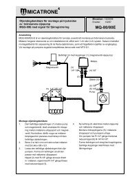
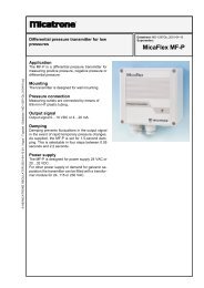
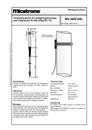
<strong>Operating</strong> <strong>and</strong> <strong>installation</strong> <strong>manual</strong>®catroneTemperature Controller withcomprehensive run-time self-supervisionMDT-2000Dok.nr: Mi-229gb / 2006-02-09© AB MICATRONE 2006-02-09 [H:\ Apps \ Typeset \ Mima \ mi-229gb_060209.vp]Prog. modeStage 1Stage 2BlockedH<strong>and</strong>0083PGMH<strong>and</strong>ESC°CAPPLICATIONMDT-2000 is a temperature controller (digital thermostat),which is intended for controlling stageburners in combustion plants. The controller is alsosuitable for controlling heating pumps, electric elementsin ventilation plants etc.FUNCTIONMDT-2000 measures the outgoing water temperaturefrom a heating boiler with a temperature sensor.The controller has two set limits for disconnectionof power stages with associated temperaturehysteresis.If there is no 230 VAC signal connected to terminal3, the controller is blocked. Terminal 5 <strong>and</strong> 6 respectiveterminal 8 <strong>and</strong> 9 are connected to each other viarelay contacts.If permission to operate is given, i.e. a 230 VAC signalon terminal 3, <strong>and</strong> the temperature is below setvalue for "Stage 1 OFF" minus the temperature hysteresisfor stage 1, the first relay switches, breaksconnection between terminal 5 <strong>and</strong> 6 <strong>and</strong> connectsterminal 4 with 5. When the temperature exceeds"Stage 1 OFF", the first relay switches back, breaksconnection between terminal 4 <strong>and</strong> 5 <strong>and</strong> connectsterminal5with6.During permission to operate, if the temperaturefalls below value for "Stage 2 OFF" minus the temperaturehysteresis for stage 2, the second relayswitches, breaks connection between terminal 8<strong>and</strong> 9 <strong>and</strong> connects terminal 7 with 8. When thetemperature exceeds "Stage 2 OFF", the second relayswitches back, breaks connection between terminal7 <strong>and</strong> 8 <strong>and</strong> connects terminal 8 with 9.MDT-2000 can also be operated <strong>manual</strong>ly using theh<strong>and</strong> operation.SELF-SUPERVISIONMDT-2000 monitors the measuring signal from thetemperature sensor to be within the measuringrange of 0...150 °C.If the measuring signal is outside the measuringrange the operation is blocked <strong>and</strong> the display starttoflash"----",relaysswitch-over<strong>and</strong>terminal5<strong>and</strong> 6 with terminal 8 <strong>and</strong> 9 closes.The run-time self-supervision stops the operationunder the following circumstances: No temperature sensor is connected Faulty connected temperature sensor Short-circuit in the temperature sensor Break inside the temperature sensor Malfunctioning wiring between the temperaturesensor <strong>and</strong> MDT-2000MDT-2000 returns to normal operation as soon asthe measuring signal is within the measuring rangeagain.DESIGNMDT-2000 is equipped with three connected printedcircuit boards, I/O-board, sensor-board <strong>and</strong> display-board.The display-board consists of a 4-digitindicator, 6 LED’s for indication <strong>and</strong> 4 keys for programming.The enclosure is of ABS plastic <strong>and</strong> providedwith four threaded holes for cable fittings. Forfitting on DIN-rail a mounting kit is used. MDT-2000can be programmed without opening the enclosure.INSTALLATIONMDT-2000 is mounted via 4 screws, max 4 mm.The location of the holes is shown back of the enclosure.Do not place the unit on a warm surface.Connect power supply according to the electricalconnection. Check that the controller is marked withthe correct power supply voltage. If using cablegl<strong>and</strong>s without a nut on the inside, gl<strong>and</strong>s withgrommet must be used to avoid damage to thethreads on the enclosure. Remember to remove thetransparent protective cover from the front panel afterfinished <strong>installation</strong>.INSTALLING THE TEMPERATUR SENSORThe temperature sensor can be connected with twoor four wires. The best result is received with a4-wire connection. A 2-wire connection is easier toinstall but results in a risk for measurement error inconnections with long wires.Ex. a 10m 2x0,25 mm 2 Cu-cable gives an error inmeasurement with approximately 3,5 °C. Shieldedcable is recommended.
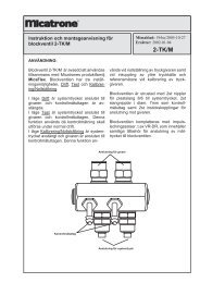
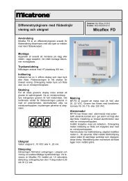
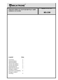
TEMPERATURE SENSORThe choice of sensor, measuring place <strong>and</strong><strong>installation</strong> are very important to achieve an accurate<strong>and</strong> representative temperature measurement.The factors to consider are: Good circulation. Good thermal contact between sensor <strong>and</strong> medium. The time constant (the response time for temperaturechanges) should be as short as possible. The sensor should not be exposed to heat radiation. The sensor should not be exposed to vibrations. The water flow should not be to high for thesensor<strong>Micatrone</strong> delivers the sensors MG-3000-DV-120,MG-3000-DRT-125 <strong>and</strong> MG-3000-DRT-225 fortemperature measuring in liquid.MG-3000-DV-120This sensor shall be installed without a pocket, butwith a compression fitting. This means that it is possibleto disconnect the sensor with water in the system.It can also be used for tubes with different kindof lengths.With this construction a very good thermal contactwith the media is achieved <strong>and</strong> the time constant(the response time for temperature change) becomesshort.The sensor pipe has a small diameter why the radiationis small. The sensor application is limited dueto the water velocity, may not exceed 2 m/s, <strong>and</strong> thatthe system pressure not exceeds 10 bar (1 MPa).The sensor is also sensitive against vibrations. Ifthese restrictions not are applicable the use ofMG-3000-DV-120 is recommended.MG-3000-DRT-125 / -225These sensors are provided with pockets <strong>and</strong> areused when MG-3000-DV-120 can't be used. Thesensors, with a pocket, has a restricted thermalcontact with the media <strong>and</strong> this gives a longer timeconstant. To reduce this the sensors shall always beinstalled upright so the pocket can be filled withglycerine. With glycerine in the pocket the time constantwill be reduced to less than half.Installation of sensors on water pipesIn order the get a quick response, the sensor shouldbe placed close to the outlet from the boiler. If wateris supplied from different directions the sensorshould be placed a least 0.2 meters from the mixingpoint so a blend of the water can occur.In pipes with small diameters there is a problem withplacement of sensors. The sensors pipe or pocketmust be installed in the waterpipe with minimumtwice the lenght of the mesurement element.For MG-3000-DV-120: 2 x 20 mm = min. 40 mmFor MG-3000-DRT-xxx: 2 x 35 mm = min. 70 mmFollowing figures shows a suitable <strong>installation</strong> inwater pipes with small diameters, either in a pipecurve or in an angle against the flow.Notice! MG-3000-DRT-xxx must be installed fromabove so the pocket can be filled with glycerine.figure 1Installation of MG-3000-DRT-xxx.figure 2Alternative <strong>installation</strong> of MG-3000-DRT-xxx.MG-3000-DV-120 do not require an <strong>installation</strong> fromabove, due to that it does not have a pocket whichneeds to be filled with glycerine.figure 3Installation of MG-3000-DV-120figure 4Alternative <strong>installation</strong> of MG-3000-DV-120© AB MICATRONE 2006-02-09 [H:\ Apps \ Typeset \ Mima \ mi-229gb_060209.vp]2
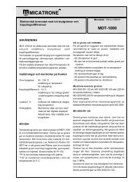
Incorrect !figure 5Pipes with larger diametres (Ø 150 <strong>and</strong> bigger) thesensors can be installed according to figure 5.figure 6Incorrect <strong>installation</strong>Notice! Never install a temperature sensor with onlythe tip in the water or the sensor in the flange.© AB MICATRONE 2006-02-09 [H:\ Apps \ Typeset \ Mima \ mi-229gb_060209.vp]Table for the resistance in Pt-100 temperature sensor (acc. DIN 43760)Pt-100 = 100 at 0 °C. All values in .°C -9 -8 -7 -6 -5 -4 -3 -2 -1 0-40 80,65 81,04 81,44 81,83 82,23 82,63 83,02 83,42 83,81 84,21-30 84,61 85,00 85,40 85,79 86,19 86,59 86,98 87,38 87,77 88,17-20 88,57 88,96 89,36 89,75 90,15 90,55 90,94 91,34 91,73 92,13-10 92,52 92,92 93,31 93,71 94,10 94,49 94,89 95,28 95,68 96,070 96,46 96,86 97,25 97,64 98,04 98,43 98,82 99,21 99,61 100,00°C +0 +1 +2 +3 +4 +5 +6 +7 +8 +90 100,00 100,39 100,78 101,17 101,56 101,95 102,34 102,73 103,12 103,5110 103,90 104,29 104,68 105,07 105,46 105,85 106,24 106,63 107,02 107,4020 107,79 108,18 108,57 108,96 109,35 109,73 110,12 110,51 110,90 111,2830 111,67 112,06 112,45 112,83 113,22 113,61 113,99 114,38 114,77 115,1540 115,54 115,93 116,31 116,70 117,08 117,47 117,85 118,24 118,62 119,0150 119,40 119,78 120,16 120,55 120,93 121,32 121,70 122,09 122,47 122,8660 123,24 123,62 124,01 123,39 124,77 125,16 125,54 125,92 126,31 126,6970 127,07 127,45 127,84 128,22 128,60 128,98 129,37 129,75 130,13 130,5180 130,89 131,27 131,66 132,04 132,42 132,80 133,18 133,56 133,94 134,3290 134,70 135,08 135,46 135,84 136,22 136,60 136,98 137,36 137,74 138,12°C +0 +1 +2 +3 +4 +5 +6 +7 +8 +9100 138,50 138,88 139,26 139,64 140,02 140,39 140,77 141,15 141,53 141,91110 142,29 142,66 143,04 143,42 143,80 144,17 144,55 144,93 145,31 145,68120 146,06 146,44 146,81 147,19 147,57 147,94 148,32 148,70 149,07 149,45130 149,82 150,20 150,57 150,95 151,33 151,70 152,08 152,45 152,83 153,20140 153,58 153,95 154,32 154,70 155,07 155,45 155,82 156,29 156,57 156,94150 157,31 157,69 158,06 158,43 158,81 159,18 159,55 159,93 160,30 160,67160 161,04 161,42 161,79 162,16 162,53 162,90 163,27 163,65 164,02 164,39170 164,76 165,13 165,50 165,87 166,24 166,61 166,98 167,35 167,72 168,09180 168,46 168,83 169,20 169,57 169,94 170,31 170,68 171,05 171,42 171,79190 172,16 172,53 172,90 173,26 173,63 174,00 174,37 174,74 175,10 175,47table 13
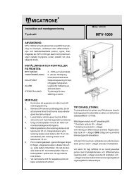
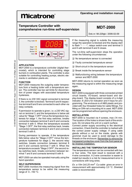
PROGRAMMINGPress the PGM-key for, at least, 3 seconds <strong>and</strong> thedisplay will change from actual value to the parameterlist’s first parameter P00. The parameter listcomprises five parameters. It's not possible tochange the first one.Press the -keys to show P00, P01, P02, P03<strong>and</strong> P04.By pressing the PGM-key, the set value is displayedfor the present parameter.To change the set value, press the PGM-key once<strong>and</strong> the left digit starts to flash. To change the digit,use the -keys <strong>and</strong> press the PGM-key to storethe selected digit. Now the next digit to the rightstarts to flash <strong>and</strong> can be programmed. Repeat withthe remaining digits for the entire row <strong>and</strong> press a finaltime on the PGM-key. The display will flash threetimes with the programmed value as a receipt of accomplishedprogramming.Present programming can be interrupted before thelast digit through pressing the ESC-key.When a value has been programmed a return to theparameter list occurs automatic.Par.nr:Parameter list Range FactorydefaultP00 Software version XXXP01 Stage 1 OFF 0...150 90 °CP02 Hysteresis stage 1 1...99 10 °CP03 Stage 2 OFF 0...150 82 °CP04 Hysteresis stage 2 1...99 5 °CDuring programming, the LED ”Prog. mode” is lit.Return to indication of actual value occurs by pressingthe ESC-key, at which the LED “Prog. mode” isput out <strong>and</strong> the LED “°C” is lit. If MDT-2000 is left inposition “Prog.mode” <strong>and</strong> no keys has beenpressed during 5 minutes, MDT-2000 will automaticlyreturn to showing the actual value.RUN IN HAND OPERATIONPress both PGM- <strong>and</strong> ESC-key for, at least, 3 seconds.The LED ”H<strong>and</strong>” is lit <strong>and</strong> the controller is disabled.By pressing -keys, wanted power stagecan be chosen, se table below.:Power stage Relay 1 Relay 2Stopped Terminal 5 <strong>and</strong> 6connectedStage 1 Terminal 4 <strong>and</strong> 5connectedStage 2 Terminal 4 <strong>and</strong> 5connectedTerminal 8 <strong>and</strong> 9connectedTerminal 8 <strong>and</strong> 9connectedTerminal 7 <strong>and</strong> 8connectedSUPERVISION DURING HAND OPERATIONIf the temperature exceeds the set value in parameterP01, "Stage 1 OFF", MDT-2000 switches toStopped immediately. Another power stage can beselected, by pressing the -key when the temperatureis below set value in parameter P01.Notice! Position h<strong>and</strong> operation do not consider settemperature hysteresis.STOP HAND OPERATIONH<strong>and</strong> operation can be stopped in two ways:• Pressing the ESC-key.• If no keys has been pressed during the past 30minutes.The LED ”H<strong>and</strong>” is put out <strong>and</strong> the MDT-2000 revertsto normal operation.Example for 2-stage burners (factory default):°C10099Protection temperature limiter© AB MICATRONE 2006-02-09 [H:\ Apps \ Typeset \ Mima \ mi-229gb_060209.vp]90P01, Stage 1 OFF828077P03, Stage 2 OFFP02, Hysteresis stage 1 (stage 1 ON)P04, Hysteresis stage 2 (stage 2 ON)70figure 74
© AB MICATRONE 2006-02-09 [H:\ Apps \ Typeset \ Mima \ mi-229gb_060209.vp]TECHNICAL DATAPower supply voltage: 230 VAC 10% 50HzPower consumption: 7.5 VAAmbient temperature: 0...55 °CIndication:4 7-segments LED's <strong>and</strong>6 function LED’s.Programming: 4 keysTemperature sensor: Pt-100Connection to the temperaturesensor:4-wire or 2-wireMeasuring range: 0..150° C (calibrated at50 <strong>and</strong> 100 °C)Measurement error: 1° CNumber of set limits: 2, one for each stage,0..150 °CTemperature hysteresis: 2, one for each set limit,1..99 °COutput relays:2 pcs, one for eachstage.Max. load, relays: 230 VAC 2A cos =1Signal for operationconditions:230 VAC Notice! Thesame line as terminal 1Converting from MDT-1000 to MDT-2000TerminalsMDT-2000Electrical connections:- power supply voltage:- relays:- sensor:Cable lead-through:Degree of protection:Dimensions: [WxHxD]:Weight:2x1,5 mm 2 /terminal2x1,5 mm 2 /terminal2x0,75 mm 2 /terminal4 threaded holes,(2 pcs M16 + 2 pcs M20)IP65120 x 200 x 57 mm0,75 kgCONNECTING SHIELDED CABLE TO SENSORIf a shielded cable is used (recommended), theshield should be connected to ground in MDT-2000.This is easiest done by connecting incoming groundwire with the shield to the terminal on the circuitboard marked with ground symbol.This terminal is not connected anywhere else on thecircuit board or in MDT-2000. For safety reasonsthe terminal is not to be used for anything else otherthen to connect the ground wire to the cable shieldfor the temperature sensor.1 2 3 4 5 6 7 8 9 11 12 13 14230 VACTerminalsMDT-10001 2 3 4 5 6 7 8 9 10 11LineNeutral{Powersupply230 VAC{{Stage 1Stage 2figure 8Converting from MDT-1000 to MDT-2000Protectional earthfor functional grounding5
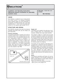
ELECTRICAL CONNECTIONMDT-20001 2 3 4 5 6 7 8 9 11 12 13 14 15+Operation230 VACProtectiontemperaturelimiter°CProtectionpressurelimiterPProtectionwaterlevellimiterLPower Linesupply230 VAC Neutral{FlowmonitorF**)L N T2 T1 T8 T6StartInStage 1*)StopStartInStage 2T7Stop{{Pt-1002-wirePt-100 4-wireTerminals in burner(EUROSTECKER)*) Sequence controller, for instance MVP-300 or MVP-3000**) Limit switch at burner flangefigure 9Electrical connectionRelay contacts for MDT-2000 are drawn as:1. No power on terminal 12. No power on terminal 33. Temperature higher thanStage 1 OFF <strong>and</strong> Stage 2 OFF© AB MICATRONE 2006-02-09 [H:\ Apps \ Typeset \ Mima \ mi-229gb_060209.vp]AB <strong>Micatrone</strong> Telephone: +46 8-470 25 00Åldermansvägen 3 Fax: +46 8-470 25 99SE-171 48 SOLNA Internet: www.micatrone.seSWEDEN E-mail: info@micatrone.se6