INSTRUCTION MANUAL - Dover Flexo Electronics, Inc
INSTRUCTION MANUAL - Dover Flexo Electronics, Inc
INSTRUCTION MANUAL - Dover Flexo Electronics, Inc
Create successful ePaper yourself
Turn your PDF publications into a flip-book with our unique Google optimized e-Paper software.
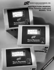
<strong>INSTRUCTION</strong> <strong>MANUAL</strong>TRUE TENSION INDICATORModels TI17B and TI18BDOC 801-1741 R3
217 Pickering RoadRochester, NH 03867-4630 U.S.A.For assistance, please call:TECHNICAL SERVICE - Installations, Start-Up, Troubleshooting, Repairs, FieldService, Returns. techsupport@dfe.comCUSTOMER SERVICE - Replacement Parts, Individual Products, Questions aboutOrders, Manuals. customerservice@dfe.comSALES - Product Information, Systems Application Questions, andplacing orders for standard products and specialsystems. sales@dfe.comTelephone: (603) 332-6150 Fax: (603) 332-3758E-mail: info@dfe.com Internet: www.dfe.com©2007 <strong>Dover</strong> <strong>Flexo</strong> <strong>Electronics</strong>, <strong>Inc</strong>. All rights reserved. <strong>Dover</strong> <strong>Flexo</strong> <strong>Electronics</strong> has made reasonable effort to ensure accuracy of thisdocument. However NO WARRANTY, whether expressed or implied, is given regarding the completeness or correctness of information inthis document. <strong>Dover</strong> <strong>Flexo</strong> <strong>Electronics</strong> shall not be liable for damages of any kind arising from the use or misuse of this document. <strong>Dover</strong><strong>Flexo</strong> <strong>Electronics</strong> reserves the right to make changes, additions, and deletions to this document without notice and without obligation.
TABLE OF CONTENTSSECTION ONE PRODUCT DESCRIPTION1.1 General Description ........................................ 11.2 Exploded View of TI17B and TI18B ............................ 11.3 Specifications ............................................. 21.4 Environmental Conditions ................................... 21.5 Standard Features ......................................... 21.6 Options .................................................. 31.7 Accessories .............................................. 3SECTION TWO INSTALLATION2.1 Dimensions .............................................. 42.2 Selection of Mounting Location ............................... 52.3 Safety & EMC Requirements ................................. 52.4 Installation Instructions ..................................... 62.5 Power Voltage Selection .................................... 62.6 Transducer Voltage ........................................ 62.7 Tension Output............................................ 72.8 Standard Electrical Connections .............................. 72.9 Optional Electrical Connections ............................... 8SECTION THREE CALIBRATION AND SETUP3.1 Preparation ............................................... 93.2 Mechanically Zero the Tension Meter .......................... 93.3 Calibrate the Output for Accuracy ............................. 93.4 Installation and Adjustment of Isolated Tension Output ............ 103.5 Calibration and Adjustment of Tension Limit Switch ............... 10SECTION FOUR OPERATING <strong>INSTRUCTION</strong>S ............................... 12SECTION FIVE CARE AND MAINTENANCE ................................. 13SECTION SIX TROUBLESHOOTING GUIDE ............................... 14SECTION SEVEN REPLACEMENT PARTS ................................... 15APPENDICESAPPENDIX: A Location of Jumpers and Adjustments ......................... 16B Electrical connections ...................................... 18C Transducer Electrical Connections ........................... 20D Typical Tensions of Various Materials.......................... 24E Environmental Terms ...................................... 25TERMS AND CONDITIONS OF SALE AND SHIPMENT .......... 26INDEX .................................................. 27
LIST OF ILLUSTRATIONSFIGURE: 1 Exploded View of TI17B and/or TI8B .......................... 12 Horizontal Mounting Dimensions .............................. 43 Vertical Mounting Dimensions ................................ 44 Optional Meter Dimensions .................................. 55 Option Meter Enclosure Dimensions ........................... 56 Power Voltage Selection .................................... 67 Transducer Voltage Jumpers ................................. 78 Tension Output Jumpers .................................... 79 Standard Electrical Connections .............................. 710 Optional Electrical Connections ............................... 811 Web Path ................................................ 912 Isolated Output Jumpers .................................... 1013 Tension Limit Switch Board Adjustments ....................... 1114 Replacement Part Numbers ................................. 1515 TI17B PC Board .......................................... 1616 TI18B Isolated Output Board ................................. 1617 Optional Tension Limit Switch Board ........................... 1718 Standard Electrical Connections .............................. 1819 Optional TLS External Relay Electrical Connections .............. 1920 Models C, RS, & UPB Transducer Wiring ....................... 2021 RFA Transducer Wiring ..................................... 2122 TR & NWI Transducer Wiring ................................ 2223 LT Transducer Wiring ...................................... 23
SECTION 1PRODUCT DESCRIPTION1.1 GENERAL DESCRIPTIONThe TI17B and TI18B Tension Indicators are designed to provide an interface between any type of DFE tensiontransducer, and a variable speed drive system, computer, tension recorder, or other devices for tension controland display purposes. It also has a separate output to allow the user to connect an analog meter to indicateoperating tension. The circuit card plugs into a single terminal block, to which all external connections aremade. This plug-in feature allows easy field installation and servicing.Models TI17B and TI18B are available with two mounting configurations and a choice of 0-10 Vdc or 4-20mAoutputs, including those choices as isolated outputs. Dual calibration is a standard feature.The only difference between the TI17B and the TI18B indicators is their power input requirements. The TI17Boperates on 115Vac 60Hz (230Vac 50Hz optional) and the TI18B operates on 24Vdc, power suppliedseparately.1.2 EXPLODED VIEW OF TI17B and/or TI18BFigure 1 - EXPLODED VIEW OF TI17B and/or TI18B1
1.3 SPECIFICATIONSPower Input: Voltage ..... TI17B = 115/230V 50/60Hz, TI18B = 24 VdcCurrent ..... TI17B = 0.125 / 0.080A, TI18B = 250 mATension Signal Outputs ..... 0 to +10Vdc @ 2mA OR 4 to 20mA (available isolated)..... 0 to 1mA damped meter for optional tension meterWeight ..... 0.5 lbs (0.23 kg) to 2.0 lbs (0.91 kg), depending onversion.Transducer Signal Input ..... 500 mVdc at rated load per pair (1.00Vdc for XREoption)Transducer excitation ..... 5Vdc (10V for the XRE option) jumper selectableZero (tare) range ..... 95% of transducer ratingCalibration range ..... 20 : 1Ambient temperature range ..... 32°F to 104°F (0°C to 40°C)Optional tension meter types ..... Analog 1mA, 3.5" (DFE P/N: 722-1385), or meter inenclosure (P/N: 723-1453)Standard tension meter scales ..... 0 to: 1, 5, 10, 25, 50, 100, 150, 250, 500, 10001.4 ENVIRONMENTAL CONDITIONS (Ref. Appendix D for further information)This section applies to equipment designed to be safe at least under the following conditions:• Indoor use• Altitude up to and above 2000 meters• Temperature 41° F to 104° F (5° C to 40° C)• Maximum relative humidity 80% for temperatures up to 88° F (31° C) decreasing linearly to 50% relativehumidity at 104° F (40° C).• Main supply voltage fluctuations not to exceed +/-10% of the nominal voltage.• Transient Overvoltages according to Overvoltage Categories I, II, and III. For main supply the minimum andnormal category is II• Pollution Degree 1 or 2 in accordance with IEC 6641.5 STANDARD FEATURESSOME OF THESE FEATURES REQUIRE CONFIGURATION OR EXTERNAL WIRING. REFER TOSECTION 2.4 FOR INSTALLATION <strong>INSTRUCTION</strong>S AND SECTION 2.8 FOR WIRING.• 0 to +10V Tension Output OR 4 to 20mA Tension Output. Proportional to tension. Used as an input to acontroller or instrumentation system. Both are also available as isolated outputs. See Section 3.4 forinstallation and adjustment.• 0-1mA Tension Output. A separate output used for driving an optional analog tension meter.• Meter Damping. Minimizes variation of the optional analog tension meter needle.• Power Voltage Selection. The TI17B Interface / Indicator is designed to operate at either 115Vac(standard) or 230Vac. The TI18B operates on 24Vdc.• Easily serviceable. The unit can easily be removed after unplugging the mating connector (see Accessories)• Small size. Fits where many other products cannot.• Flexible Options. Options and features can be tailored for each application.• Economical. Provides many important features at a reasonable price.• Isolated from Earth Ground. A transformer provides isolation from earth ground, simplifying installations.2
• Dual Calibration. Allows two calibration settings. Dual calibration option may be used in the followingapplications:a. One set of transducers operating in a wide tension range. Dual calibration and dual meter scale is used toenhance the resolution of indicated tension.b. One set of transducers that may be subject to two different wrap angles or web paths. In this case a dualmeter scale may, or may not, be required.• Mating Terminal Block Connector. Allows easy connection of external wiring.1.6 OPTIONSSOME OF THESE OPTIONAL FEATURES REQUIRE CONFIGURATION OR EXTERNAL WIRING. REFERTO SECTION 2.4 FOR INSTALLATION <strong>INSTRUCTION</strong>S AND SECTION 2.9 FOR WIRING.• 230 Volt Input (230). 230Volt 60/50 Hz Ac power input. TI17B only.• 4 to 20mA Output (420). 4 to 20 mA current output.• Cover (COV). Cover restricts access to board and provides complete enclosure. V version only.• DIN Rail Clip (DRC). To be used with 35 mm DIN rail. V version only.• Isolated 10V Output (I10). 0 to 10Volt output which is not connected to circuit common or to earth ground.• Isolated 20mA Output (I420). 4 to 20mA output which is not connected to circuit common or to earthground.• Extended Range (XRE). 10 Vdc excitation for Extended Range transducers. Allows measurement of a muchlower tension than usual. Transducers must also have the XR option.• Tension Limit Switch (TLS). An open collector output actuates at a pre-set adjustable trip point. Can beused as a web break detector, or high tension warning.1.7 ACCESSORIES• Remote Tension meter. Analog, 1 mA (P/N: 722-1385) supplied as a single unit. Must be installed by user.This meter is also available in its own enclosure (P/N: 723-1453).• Nonstandard meter scale. Any other meter scale than standard ones offered by DFE. See Specificationsfor standard scales. Applies to remote tension meter listed above.3
SECTION 2INSTALLATION2.1 DIMENSIONS inches (mm)Figure 2 - HORIZONTAL MOUNTING DIMENSIONSFigure 3 - VERTICAL MOUNTING DIMENSIONS4
Figure 4 - OPTIONAL TENSION METER DIMENSIONSFigure 5 - OPTIONAL TENSION METER ENCLOSURE DIMENSIONS2.2 SELECTION OF MOUNTING LOCATIONThe TI17B or TI18B must be located away from dusty or wet environments. The TI17B or TI18B Horizontalversion should be installed in a cabinet or enclosure.2.3 SAFETY AND EMC REQUIREMENTSWarning! If this equipment is not connected or operated in the manner specified, the operating safety of thisunit or of connected equipment cannot be guaranteed.Warning! The DFE Model TI17B you have purchased has been tested and meets the European Union's LowVoltage Directive and EMC Directive only when the available enclosure has been used and when installation isdone correctly. For safety reasons, it is necessary to use appropriate wiring for your line voltage connections andfor safety grounding. Make your ground connection between a reliable earth ground and the safety ground ofyour indicator using a wire with a gauge of at least 16 AWG (or a cross-sectional area of at least 1mm 2 ). Makeyour line voltage connection to TB1 positions 14 and 16 using wire with a gauge of at least 16 AWG (or a5
cross-sectional area of at least 1mm 2 ) for each conductor. Attach this wiring to the panel to prevent inadvertentremoval.An external switch or circuit breaker is required for power disconnection on the TI17B, and it is recommendedthat this switch or circuit breaker be near the equipment.In addition, to meet the EMC Directive, a proper transducer installation, including shielded cables must also beused. The following is a list of cables available from DFE which meet this requirement:721-0084 CN 3-conductor cable for type C, RS, and UPB transducers721-0964 CN 6-conductor cable for type RFA, LT, VNW, and TR1 transducers721-0984 CN 6-conductor cable for NWI and TR2.Cable shielding must be attached to chassis ground. If you wish to assemble your own cables, contact DFE forassembly instructions.2.4 INSTALLATION <strong>INSTRUCTION</strong>SDrill your mounting holes for the mounting style you will be using. Be sure to allow ample clearance beside orin front of the unit for tool access and for wiring.If you are using the vertical mounting style, drill and tap 2 holes 2.26" (57.4 mm) apart vertically Insert yourM4 or #8 screws and tighten but at the end reverse them out 3 turns. Place the enclosure keyholes over thescrewheads and lower unit into place. Tighten the screws. If you are using the horizontal mounting style, mountthe indicator circuit card to your panel. If an optional analog meter is used, drill mounting holes per dimensionsin Figure 4.2.5 POWER VOLTAGE SELECTION (TI17B Only. Refer to Appendix A for board drawing.)The True Tension TI17B is designed to operate on either 115V-50/60Hz or 230V-50/60Hz power. Verify thatyour unit is set up for the correct line voltage. See below for location of jumpers for this selection. Also verifythat the correct value fuses are installed based upon your line voltage selection. Note: These jumpers aresoldered in. If you do not feel comfortable changing these, please contact the factory before starting.Figure 6 - POWER VOLTAGE SELECTIONThe True Tension TI18B is designed to operate on 24 Vdc so no voltage selection is necessary.2.6 TRANSDUCER VOLTAGE (Refer to Appendix A for board drawing.)The tension transducers are excited by either the standard 5 Vdc or, 10 Vdc with the Extended Range option orLT (low tension) transducer.CAUTION!! Do NOT use the 10 Vdc excitation unless the transducers are LT type transducers or have theextended range option! The transducers WILL be DAMAGED!6
Set the transducer excitation jumpers as follows: 5 Vdc - jumper on JP210 Vdc - jumper on JP1Figure 7 - TRANSDUCER VOLTAGE JUMPERS2.7 TENSION OUTPUT (Refer to Appendix A for board drawing.)Verify that your TI17B or TI18B is set-up with the correct tension output. There will be a set of jumpers on J1on the main board. If 0 to 10V is required, pins 1 to 2, and 4 to 5 will have a jumper. If 4-20mA is required,pins 2 to 3, and 4 to 5 will have a jumper. See figure below.Figure 8 - TENSION OUTPUT JUMPERS2.8 ELECTRICAL CONNECTIONS - STANDARDKeep in mind that the indicator is designed to provide a 0-1mA damped meter output, and either a 0-10V OR a4-20mA output. If more than one output is used simultaneously, the outputs may not agree.Figure 9 - STANDARD ELECTRICAL CONNECTIONS7
Make your wiring connections as follows:1. The insulation rating of all line voltage wiring must be at least 300V2. Keep line voltage wiring physically separated from signal wiring at the terminal block and at any other pointin the installation. If this is not possible, the insulation rating of your signal wiring must also be at least300V.3. Connect cable shields to earth ground.2.9 TENSION LIMIT SWITCH EXTERNAL RELAY CONNECTIONS (Option)Figure 10 - TLS EXTERNAL RELAY CONNECTIONS (Option)8
SECTION 3CALIBRATION and SETUP3.1 PREPARATIONThe best way to calibrate your system is to attach the device which will be accepting the output from theindicator. Otherwise attach a voltmeter or milliammeter, as appropriate for the type of output you intend to use.3.2 MECHANICALLY ZERO THE TENSION METER(This step is necessary only if the optional analog tension meter is to be used).Turn off power to the TI17B or TI18B and observe whether the tension meter needle rests at 0. If not, turn theadjustment screw on the rear of the meter as required to set the meter needle at 0 on the scale.3.3 CALIBRATE THE OUTPUT FOR ACCURACY1. Find an object of known weight at least as heavy as 25% of the tension meters full scale output, andpreferably as close to 100% as you can find. A spring scale can also be used. Get a length of rope, wire orcable about 15 feet (3 meters) long.2. Turn on power to the TI17B or TI18B3. Turn the CAL pot (Cal A or Cal B as appropriate) clockwise at least 5 turns (this makes the ZERO A or Bpot setting more accurate). Then turn the ZERO pot as required to make the output equal to its zero point (0Vfor the 0 to 10V output; 4 mA for the 4-20mA output; 0 mA for the meter output).4. Fasten one end of the rope in the machine and thread the other end around the transducer roll in exactly thesame path as the web will take. Be sure it does not pass around any driven rolls, drag bars, or anything elsethat can affect tension. Refer to figure below.Figure 11 - WEB PATH5. Attach the weight to the free end of the rope as shown above. The weight should not touch anything. Adjustthe CAL pot (Cal A or Cal B as appropriate) as required to set the meter needle at the value of the weight.6. Remove the weight and observe the tension meter. If the needle is not on zero, adjust the ZERO pot (A or B)as needed. Repeat step 5.7. Repeat steps 5 and 6 if needed.8. If the optional analog meter is used, adjust the DAMP pot while the machine is running to minimize meterneedle movement.9. Repeat steps 3 through 8 with Cal A/B line grounded (TB1, position 3) for Dual Calibration only.The output calibration procedure is now complete.9
3.4 INSTALLATION AND ADJUSTMENT OF ISOLATED TENSION OUTPUT(Refer to Appendix A for board drawing.)Regular 0 to +10V and 4 to 20mA tension outputs are configured at factory. Verification instructions are inSection 2.7. Isolated 0 to +10V or 4 to 20mA requires the installation of an ISO card to the main TI17B orTI18B board. The following instructions are for the installation of this card and adjustment of your output.If your TI17B or TI18B was received with this Isolation card already installed, you need not make the aboveadjustments as they already have been done at the factory.CAUTION! Standard precautions against static discharge should be taken when working with any electroniccomponents.1. You will need to select your output on the isolation card prior to installing on main card by configuringjumper JP1. If 0 to 10V is required, install jumper on pins 1 and 2. If 4-20mA is required, install jumper onpins 2 and 3. See diagram belowFigure 12 - ISOLATED OUTPUT JUMPERS2. To install the isolation card, it will be necessary to remove the jumpers from J1 on the main card.3. Install the isolation card by lining up the 4 position and 6 position connectors to the J1 pin on the main card.Press the card down firmly.4. If the output for the 4mA or 20mA is not exactly 4 or 20, some further calibration can be accomplished byadjusting RT1 (20mA) and RT2 (4mA).3.5 CALIBRATION AND ADJUSTMENT OF TENSION LIMIT SWITCH OPTIONThe TLS feature is used to provide an visual LED indication when output exceeds one value or goes belowanother value. You can also connect an external relay as described in Section 2.9 to sound an external alarm,turn a machine off, and so forth.To calibrate the TLS card, you need to know your system’s full scale tension indication (TFULL). You alsoneed to decide what you want for your Low tension trip point (TLO) and your high tension trip point (THI).Note that you can set up TLS for one and not the other or both.Your system should be calibrated to measure tension prior to setting up TLS. Do NOT change the CAL A orCAL B pot settings during this procedure. Changing your cal pot settings will invalidate your calibration.Changing the Zero pot setting will not invalidate the calibration.See Figure 12 for adjustment locations.1. On the TLS card, turn RT1 (TLS Lo Trip point) 20 turns counterclockwise, RT2 (TLS Hi trip point) 20 turnsclockwise, and RT3 (TLS delay) 20 turns counterclockwise.2. Setting TLS Low Trip Point (If only TLS high is needed, skip step 2 and go to step 3).a) To set the TLS low trip point, calculate the TLO voltage as follows: Take the Low tension trip point(TLO) divide it by your full scale tension (TFULL), and multiply the result by 10 Volts:TLO voltage = TLO/TFULL x 10 Volts10
) Attach a meter to the output of the TI17B or TI18B. Connect your (-) lead to TB1-1 and + to TB1-2.Adjust the zero pot RT1 on the main TI17B or TI18B board so that your meter reads the “TLO voltage”you just calculated (for example, if your TLS low trip point TLO is 30 lbs and your full scale tensionTFULL is 75 lbs, adjust RT1 to produce 30/75 x 10V = 4.00V).c) On the TLS option card, adjust RT1 upward (clockwise) until the TLS LED just turns on.3. Setting TLS High Trip Pointa) To set the TLS high trip point, calculate the THI voltage as follows: Take the High tension trip point(THI) divide it by your full scale tension (TFULL), and multiply the result by 10 Volts:THI voltage = THI/TFULL x 10 Voltsb) With your meter still connected to TB1-1 and -2, adjust the zero pot RT1 on the main TI17B or TI18Bboard so that your output voltage reads the “THI voltage” you just calculated (for example, if your TLShigh trip point THI is 50 lbs. and your full scale tension is 75 lbs, adjust RT1 to produce 50/75 x 10V =6.67V).c) On the TLS option card, adjust RT2 downward (counterclockwise) until the TLS LED just turns on.4. If the TI17B or TI18B was calibrated prior to setting up TLS, adjust the zero pot RT1 on the main TI17B orTI18B board so that the output is 0V (make sure no web is touching the roll when you do this). You can thenremove your meter leads from TB1, and TLS setup is complete.After your unit is in operation for a while, you may find that you want to adjust RT3 (TLS delay) upward(clockwise) to prevent false triggering.Figure 13 - TENSION LIMIT SWITCH BOARD ADJUSTMENTS11
SECTION 4OPERATING <strong>INSTRUCTION</strong>SYour tension interface / indicator will indicate tension in your system without any further operator intervention.It is a good idea to make a check at roughly one month intervals to verify that no one has changed thecalibration.12
SECTION 5CARE AND MAINTENANCEIt is not necessary to perform any type of maintenance on the indicator. However, you may find it worthwhile toobserve whether there is a buildup of dust, debris, or moisture on or near the unit after a period of time. If so,you may consider putting the unit in a more appropriate enclosure.13
SECTION 6TROUBLESHOOTING GUIDEMost problems are caused by incorrect installation and misapplication of the equipment. It is very important tobe sure these factors are correct before making any changes to potentiometer and jumper settings.If your unit fails to operate, check fuses on the TI17B or TI18B. If they need to be replaced, use the correctvalues listed below:TI17B: 115V Operation 230V OperationT125mA, 250VT80mA, 250VTI18B:T250mA, 250VWarning! Equipment must be disconnected from the HAZARDOUS LIVE voltage before changingthe fuses.If you have any problems with the functions on your TI17B or TI18B Tension Indicator, please call TechnicalService at 603-332-6150 or fax 603-332-3758. E-mail: techsupport@dfe.com.DFE’s experienced technicians are responsible to ensure that you are satisfied with your DFE equipment. Theywill be pleased to assist you.14
SECTION 7REPLACEMENT PARTSSee diagram below for separate components.Warning!: When replacing fuses, use only fuses with ratings as shown below, or a lower rating. Failure to do thismay compromise personal safety and may create a fire hazard!1 - 721-1960 Mating Terminal Block Connector2 - 620-1941 Enclosure Cover123-0032 Replacement Screws, M3 x 63 - 108-0045 (2) Fuses, T125mA 250V for 115Vac - TI17B4 - 108-0057 (2) Fuses, T80mA 250V for 230Vac - TI17B5 - 108-0038 (1) Fuse, T250mA, 250V for 24Vdc - TI18B6 - 108-0005 Fuse Covers - 2 for TI17B, 1 for TI18B7 - 620-1937 DIN Rail Mounting Clip (Optional)123-0311 Replacement Screws, M4 x 0.7 x 6mm8 - 620-1938 Enclosure Base9 - 723-1439 Isolated Output Card (Optional)10 - 723-1802 Tension Limit Switch Card (Optional)11 - 323-0773 Front Overlay - TI17B323-0774 Front Overlay - TI18B12 - Spare Circuit Cards - TI17B:723-1949 TI17B H version, 723-1950 TI17B V version13 - Spare Circuit Cards - TI18B:723-1953 TI18B H Version, 723-1954 TI18B V version14 - Circuit Card Mounting Hardware123-0025 Screws, M3 x 8, 124-0048 Washer801-1741 Instruction ManualFigure 14 - REPLACEMENT PART NUMBERS15
Appendix A:Locations of Jumpers and AdjustmentsFigure 15 - TI17B and/or TI18B PC BOARD (Enlarged for clarity)Figure 16 - TI17B and/or TI18B ISOLATED OUTPUT BOARD (Enlarged for clarity)16
Figure 17 - OPTIONAL TENSION LIMIT SWITCH BOARD (Enlarged for clarity)17
Appendix B:Electrical ConnectionsTI17/18B STANDARD CONNECTIONS:Make your wiring connections as follows:1. The insulation rating of all line voltage wiring must be at least 300V2. Keep line voltage wiring physically separated from signal wiring at the terminal block and at any other pointin the installation. If this is not possible, the insulation rating of your signal wiring must also be at least 300V.3. Connect cable shields to earth ground.Figure 18 - STANDARD ELECTRICAL CONNECTIONS18
TENSION LIMIT SWITCH EXTERNAL RELAY CONNECTIONS (Option):Figure 19 - TLS EXTERNAL RELAY CONNECTIONS (OPTION)19
Appendix C:Transducer Electrical ConnectionsFigure 20 - MODELS C, RS, & UPB TRANSDUCER WIRING20
Figure 21 - RFA TRANSDUCER WIRING21
Figure 22 - TR & NWI TRANSDUCER WIRING22
Figure 23 - LT TRANSDUCER WIRING23
Appendix D:Typical Tensions for Various MaterialsTYPICAL TENSIONS FOR WEB MATERIALSACETATE0.5 lb. per mil per inch of widthFOIL Aluminum 0.5 lb. per mil per inch of widthCopper 0.5 lb. "CELLOPHANENYLON0.75 lb. per mil per inch of width0.25 lb. per mil per inch of widthPAPER 15 lb * 0.4 lb. per inch of width20 lb 0.5 lb. "30 lb 0.75 lb. "40 lb 1.25 lb. "60 lb 2.0 lb. "80 lb 3.0 lb. "100 lb 4.0 lb. "* based on 3000 sq. ft. reamPAPERBOARD 8pt 3.0 lb. per inch of width12pt 4.0 lb. "15pt 4.5 lb. "20pt 5.5 lb. "25pt 6.5 lb. "30pt 8.0 lb. "POLYETHYLENEPOLYESTER (Mylar)POLYPROPYLENEPOLYSTYRENE0.12 lb. per mil per inch of width0.75 lb. per mil per inch of width0.25 lb. per mil per inch of width1.0 lb. per mil per inch of widthRUBBER GAUGE AT 25% STRETCH AT 50% STRETCH10 mil 1.75 3.6812 mil 1.10 2.0316.5 mil 4.09 8.1726 mil 2.47 4.97SARAN0.15 lb per mil per inch of widthSTEEL GAUGE - INS UNWIND-PSI REWIND-PSI0.001 -0.005 1000 40000.006 -0.025 850 35000.026 -0.040 750 30000.041 -0.055 650 26000.058 -0.070 550 22000.071 -0.090 450 18000.091 -0.120 450 14000.121 -0.140 400 12000.141 -0.165 400 10000.166 -0.200 400 9000.201 -0.275 400 8000.276 -0.380 300 700VINYL0.05 lb. per mil per inch of width*** For laminated webs, sum the tension for the individual webs and add 0.1 lb per inch of width.24
Appendix E:Environmental TermsOVERVOLTAGE CATEGORY: Classification of parts of installation systems or circuits with standardizedlimits for transient overvoltages, dependent on the normal line voltage to earth. (Ref. IEC 664)POLLUTION: Any addition of foreign matter, solid, liquid or gaseous (ionized gases), that may produce areduction of dielectric strength or surface resistivity.POLLUTION DEGREE: For the purpose of evaluating clearances the following two degrees of POLLUTION inthe micro-environment are recognized for use in accordance with IEC 664.POLLUTION DEGREE 1: No POLLUTION or only dry non-conductive POLLUTION occurs. The POLLUTIONhas no influence.POLLUTION DEGREE 2: Normally only non-conductive POLLUTION occurs. Occasionally, however, atemporary conductivity caused by condensation must be expected.25
TERMS AND CONDITIONS OF SALE AND SHIPMENT1. THE COMPANY 5/1/00<strong>Dover</strong> <strong>Flexo</strong> <strong>Electronics</strong>, <strong>Inc</strong>. is hereinafter referred to as theCompany.2. CONFLICTING OR MODIFYING TERMSNo modification of, additions to or conflicting provisions to theseterms and conditions of sale and shipment, whether oral or written,incorporated into Buyer's order or other communications are bindingupon the Company unless specifically agreed to by the Company inwriting and signed by an officer of the Company. Failure of theCompany to object to such additions, conflicts or modifications shallnot be construed as a waiver of these terms and conditions nor anacceptance of any such provisions.3. GOVERNING LAWThis contract shall be governed by and construed according to thelaws of the state of New Hampshire, U.S.A. The parties agree thatany and all legal proceedings pursuant to this contract shall takeplace under the jurisdiction of the courts of the State of NewHampshire in the judicial district of Strafford County.4. PENALTY CLAUSESPenalty clauses of any kind contained in orders, agreements or anyother type of communication are not binding on the Company unlessagreed to by an officer of the Company in writing.5. WARRANTY<strong>Dover</strong> <strong>Flexo</strong> <strong>Electronics</strong>, <strong>Inc</strong>. warrants its' products to be free ofdefects in material and workmanship for five years from date oforiginal shipment. Warranty is valid on products purchased on orafter April 2, 1999. During the warranty period the Company willrepair or replace defective products free of charge if such productsare returned with all shipping charges prepaid and if, upon examination,the product is shown to be defective. This warranty shall notapply to products damaged by abuse, neglect, accident, modification,alteration or mis-use. Normal wear is not warranteed. All repairsand replacements under the provisions of this warranty shall bemade at <strong>Dover</strong> <strong>Flexo</strong> <strong>Electronics</strong> or at an authorized repair facility.The Company shall not be liable for expenses incurred to repair orreplace defective products at any other location or by unauthorizedpersons or agents. This warranty contains all of the obligations andwarranties of the Company. There are no other warranties, eitherexpressed or implied. No warranty is given regarding merchantabilityor suitability for any particular purpose. The Company shall not beliable in either equity or law for consequential damages, losses orexpenses incurred by use of or inability to use its' products or forclaims arising from same. No warranty is given for products of othermanufacturers even though the Company may provide theseproducts with its' own or by themselves. The provisions of thiswarrantycan not be changed in any way by any agent or employee of theCompany. Notice of defects must be received within the warrantyperiod or the warranty is void.6. PAYMENTSStandard terms of credit are net 30 days from date of shipment,providing satisfactory credit is established with the Company.Amounts past due are subject to a service charge of 1.5% per monthor portion thereof or 18% per annum. The Company reserves theright to submit any unpaid late invoices to a third party for collectionand Buyer shall pay all reasonable costs of such collection in additionto the invoice amount. All quoted prices and payments shall bein U.S. Dollars.If the Company judges that the financial condition or paymentpractices of the Buyer does not justify shipment under the standardterms or the terms originally specified, the Company may require fullor partial payment in advance or upon delivery. The Company reservesthe right to make collection on any terms approved in writingby the Company's Finance Department. Each shipment shall beconsidered a separate and independent transaction and paymenttherefore shall be made accordingly. If the work covered by thepurchase order is delayed by the Buyer, upon demand by Companypayments shall be made on the purchase price based uponpercentage of completion.7. TAXESAny tax, duty, custom, fee or any other charge of any naturewhatsoever imposed by any governmental authority on or measuredby any transaction between the Company and the Buyer shall bepaid by the Buyer in addition to the prices quoted or invoiced.8. RETURNSWritten authorization must be obtained from the Company's factorybefore returning any material for which the Buyer expects credit, exchange,or repairs under the Warranty. Returned material (exceptexchanges or repairs under the Warranty) shall be subject to aminimum re-stocking charge of 15%. Non-standard material or othermaterial provided specially to the Buyer's specification shall not bereturnable for any reason. All material returned, for whatever reason,shall be sent with all freight charges prepaid by the Buyer.9. SHIPPING METHOD AND CHARGESAll prices quoted are F.O.B. the Company's factory. The Companyshall select the freight carrier, method and routing. Shipping chargesare prepaid and added to the invoice of Buyers with approved credit,however the Company reserves the right to ship freight-collect if itprefers. Shipping charges will include a charge for packaging.Company will pay standard ground freight charges for items beingreturned to Buyer which are repaired or replaced under theWarranty.10. CANCELLATION, CHANGES, RESCHEDULINGBuyer shall reimburse Company for costs incurred for any item onorder with the Company which is canceled by the Buyer. Costs shallbe determined by common and accepted accounting practices.A one-time hold on any item ordered from the Company shall beallowed for a maximum of 30 days. After 30 days, or upon notice of asecond hold, Company shall have the right to cancel the order andissue the appropriate cancellation charges which shall be paid byBuyer. Items held for the Buyer shall be at the risk and expense ofthe Buyer unless otherwise agreed upon in writing. Companyreserves the right to dispose of canceled material as it sees fitwithout any obligation to Buyer.If Buyer makes, or causes to make, any change to an order theCompany reserves the right to change the price accordingly.11. PRICESPrices published in price lists, catalogs or elsewhere are subject tochange without notice and without obligation. Written quoted pricesare valid for thirty days only.12. EXPORT SHIPMENTSPayment for shipments to countries other than the U.S.A. andCanada or to authorized distributors shall be secured by cash inadvance or an irrevocable credit instrument approved by an officerof the Company. An additional charge of 10% will apply to any letterof credit. There will be an extra charge for packaging anddocumentation.13. CONDITION OF EQUIPMENTBuyer shall keep products in good repair and shall be responsible forsame until the full purchase price has been paid.14. OWNERSHIPProducts sold are to remain the property of the Company until fullpayment of the purchase price is made.26
INDEX0-1 mA ............................. 20-10 Volt Tension Output............... 2230 Volt Power ....................... 24-20mA............................. 2AC Power Connections ................ 17Accessories ......................... 3Cables ............................. 6Calibration,range ............................ 2tension meter ...................... 8Care and Maintenance ................ 12Circuit Card ......................... 14-16connector, ............................................. 1, 3, 14Descriptions ......................... 1Dimensions ......................... 4-5Din Rail Clip ......................... 3Disassembly......................... 1Electrical Connectionsstandard. ......................... 7, 17optional ........................... 7, 18transducer ........................ 19-22Environmental Conditions .............. 2terms............................. 24Excitation ........................... 2Exploded View ....................... 1Extended Range ..................... 3Fuses ............................................................ 6, 14Input ............................... 2Installation .......................... 4Isolation from Earth Ground ............. 2Meter,analog ............................ 2calibration ......................... 8damping .......................... 2, 8dimensions ........................ 5mechanical Zero .................... 8meter scales....................... 2non-standard meter scales ........... 3remote tension meter ................ 3Mounting Location .................... 5Operating Instructions ................. 11Options............................. 3Output,0-1 mA ........................... 24-20mA........................... 2, 170 to +10V ......................... 2, 17Isolated........................... 10PC Boards .......................... 15-16Power Voltage Selection ............... 2, 6Replacement Parts ................... 14Safety Requirements .................. 5Set-up.............................. 8Specifications........................ 2Standard Features .................... 2Tension Limit Switch .................. 3, 18Tension Meter ....................... 2,9output ............................ 7standard scales .................... 2Temperature Range ................... 2Terms & Conditions ................... 26Transducer,cables ............................ 6connections ....................... 19-22excitation ......................... 2, 7input ............................. 2Troubleshooting ...................... 13Typical Tensions ..................... 23Weight ............................. 2Zero ............................... 8range ............................ 227
217 PICKERING ROADROCHESTER, NEW HAMPSHIRE 03867-4630 U.S.ATEL: 603-332-6150FAX: 603-332-3758E-mail: info@dfe.com Internet: www.dfe.comCANADAMEXICOUNITED KINGDOMEUROPETAIWANKOREAAUSTRALIACOLOMBIAINDIASOUTH AFRICA©2007 DOVER FLEXO ELECTRONICS, INC DOC 801-1741 R3ALL RIGHTS RESERVED F & C 0307 PRINTED IN USA


