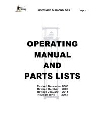
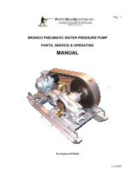
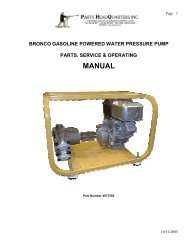
Bazooka Drill Manual - Parts HeadQuarters Inc
Bazooka Drill Manual - Parts HeadQuarters Inc
Bazooka Drill Manual - Parts HeadQuarters Inc
- No tags were found...
Create successful ePaper yourself
Turn your PDF publications into a flip-book with our unique Google optimized e-Paper software.
Page 1BAZOOKA DIAMOND DRILLPARTS, SERVICING & OPERATINGMANUAL11/31/08
Page 2TABLE OF CONTENTSSAFETY PRECAUTION – Noise Levels Page 3GENERAL INFORMATIONHow to Order Page 4Terms and Conditions Page 5Standard Terms of Sale Page 6OPERATINING AND SERVICING INSTRUCTIONS<strong>Bazooka</strong> <strong>Drill</strong> with Eye Bolt Anchor and Bipod Set-Up Page 7Picture of <strong>Bazooka</strong> <strong>Drill</strong> Assembly with Bipod Set-Up Page 8PARTS MANUALSMaster <strong>Parts</strong> List – Part# 2504058 <strong>Bazooka</strong> <strong>Drill</strong> with 24” Feed Page 9Master <strong>Parts</strong> Schematic – Plate 724 – <strong>Drill</strong> Assembly Page 10<strong>Parts</strong> List – Part# 2910414 - Muffler Kit Page 11<strong>Parts</strong> Schematic – Plate M – Muffler Kit Page 12<strong>Bazooka</strong> Controls – <strong>Drill</strong>ing Position Page 13<strong>Bazooka</strong> Controls – Retract Position Page 14Column Bar Mounted <strong>Bazooka</strong> Page 15Column Bars and Clamps Mine Jack Page 16<strong>Parts</strong> List – Part# 2504029 – Piping Assembly Page 18<strong>Parts</strong> Schematic – Plate 723 – Piping Assembly Page 19<strong>Parts</strong> List – Part# 2504022 – Bipod Assembly Page 20<strong>Parts</strong> Schematic – Plate 309 – Bipod Assembly Page 21<strong>Parts</strong> List – Part# 2504005 – Cylinder Assembly 24” Page 22<strong>Parts</strong> Schematic – Plate 305A – Cylinder Assembly 24” Page 23<strong>Parts</strong> List – Part# 2504002 – Motor Adapter Group Page 24<strong>Parts</strong> Schematic – Plate 307 – Motor Adapter Group Page 25<strong>Parts</strong> List – Part# 2502003 – BVB6 Vane Motor 16 Hp Page 26<strong>Parts</strong> Schematic – Plate 468 – BVB6 Vane Motor 16 Hp Page 27PHQ F61 LARGE CAPACITY DUAL FEED LUBRICATORDescription of F61 Lubricator and Flow Adjustment Page 28Features and Specifications of F61 Lubricator Page 29<strong>Parts</strong> List – F61 Lubricator Page 30<strong>Parts</strong> Schematic – F61 Lubricator Page 31PARTS HEADQUARTERS INC INFORMATION Page 3211/31/08
Page 3Safety Precaution – Noise Levels11/31/08
Page 4GENERAL INFORMATIONHOW TO ORDERA formal purchase order on company letterhead mailed or faxed is satisfactory. Email ordersare satisfactory if full company details are provided. Telephone orders should be confirmed inwriting through mail, fax or Email.The purchase order should contain: the full company name, address, phone and fax numbers(for quick reference or clarification) as well as details to contact the authorizing purchasingpersonnel.Please list on the purchase order: quantity, part number, item description, price, shippingaddress and preferred routing for shipmentsWhen ordering complete machines or major assemblies please furnish complete descriptions ofthe power unit required, sprocket ratios preferred, swivelhead type, chuck jaws sizes, and otherrelative information of standard optional equipment preferred.When ordering pumps please furnish complete description of the power unit required, thesprocket size preferred, the bore size, if a transmission, chain or belt drive is preferred and ifgear reduction is required.Mail or fax orders to:WHERE TO SEND THE ORDEREmail orders to:Larry MeyerRob Leelarry@partshq.comrob@partshq.com11/31/08
Page 5TERMS AND CONDITIONSTERMSNORTH AMERICA: Net 30 days on approved creditOverdue payment of invoices incur monthly interest charges of 1.5%)EXPORT SALES : Confirmed irrevocable letter of credit drawn on Canadian BankNet 30 days credit terms available through Canadian EDC guaranteesIf purchasing company has an acceptable EDC credit ratingVisa or MasterCard acceptable for payment with referencesPayment in advance of shipment by wire transfer to Canadian BankDELIVERYMost items are available from stock and you will receive a confirmed order acknowledgementspecifying shipment date. Shipments will be routed by the most direct and economical means oftransportation unless otherwise specified and your order should indicate if partial orders areacceptable.RETURN OF GOODSGoods may be returned with the advance express written permission of <strong>Parts</strong> <strong>HeadQuarters</strong> <strong>Inc</strong>.Goods returned are subject to 25% restocking charges. Special equipment is not returnable.Only new drilling material is returnable. No credit will be issued for used drill material or tools.<strong>Parts</strong> <strong>HeadQuarters</strong> <strong>Inc</strong>. retains the right to inspect and reject any material returned for creditand to deny credit for any goods judged not to be suitable for resale.GENERAL INFORMATIONPrices and specifications listed are subject to change at any time without notice.Quotations for products are dated and valid for no more than 60 days from the date shown.All prices are F.O.B. <strong>Parts</strong> <strong>HeadQuarters</strong> <strong>Inc</strong> warehouse, Burlington, Ontario, Canada, L7L 5H9.Federal and Provincial taxes where applicable are extra and charged on PHQ invoices.The cost of exporting documents and insurance may be added and shown on PHQ invoices.Prepaid freight and handling charges may be added and shown on PHQ invoices.11/31/08
Page 611/31/08
Page 711/31/08
Page 811/31/08
Page 911/31/08
Page 1011/31/08
Page 1111/31/08
Page 1211/31/08
Page 13BAZOOKA CONTROLS - DRILLING POSITION7A DIRECTIONAL CONTROL VALVE SHOWN IN THEFORWARD FEED DRILLING POSITION.7 ADVANCE CONTROL VALVE SHOWN IN THEFORWARD FEED DRILLING POSITION10 THROTTLE VALVE (DRILL ROTATION CONTROL)21 FEED CONTROL NEEDLE VALVE USED TOSET FLOW OF AIR TO CYLINDER FOR FEED21 ADVANCE CONTROL VALVE IN THE ON POSITIONALLOWS AIR TO FLOW FROM AIR SUPPLYTHROUGH FEED CONTROL NEEDLE VALVE TO THEPISTON ROD (AIR FLOWS THROUGH THE PISTONROD TO THE BACK OF THE CYLINDER TO BUILDFEED PRESSURE FOR DRILLING.15 WATER VALVE IN THE FULL ON POSITION.PIPING CONFIGURATION IS TO BE AS SHOWN TO OPERATE THE DRILL FOLLOWING INSTRUCTIONS.A PROPER CONTROL PIPING SCHEMATIC IS ILLUSTRATED IN PLATE 723 ON PAGE 15 OF THE MANUAL.<strong>Drill</strong>ing Operations:Inspect lubricator (Page 24) to insure adequate oil supply. Lubricant should be visible through the fill port.Check controls are in the off position (see BAZOOKA CONTROLS SET IN THE RETRACT POSITION Page 13).Turn on the air supply and water supply at the header.- Rotate the feed control needle valve (21) to off.- Move advance control lever (7A) and feed control lever (7) to the positions shown in the illustration.- Gradually increase feed pressure by slowly turning the feed control needle valve (21)- Advance the bit to the face. Reversing the advance control lever (7) will stop forward feed.- TIP The feed can be “sticky” or “jerky” at first when the drill has not been operated for a period of time.It is advisable to move the drill back and forwards several times until the feed and retract motion is smooth- Begin slow rotation of the drill rods by opening throttle valve (10) supplying air to the rotation motor.- Gradually increase rotation speed by turning and opening the throttle valve (10)- Once the bit has penetrated the face turn the water valve (6) on.- Monitor flow of water and adjust valve (6) until adequate flow is observed.- Adjust feed pressure, rotation speed and water flow until satisfactory drilling performance is observed.- Monitor the drill at all times during drilling operations to maintain optimum drill performance.o Observe water flow to be sure of continuous supply.o Observe smooth rotation of drill rods and take action if sudden changes occur.- When drill reaches end of the run reverse the advance control lever (7) to stop forward feed- Turn off rotation by closing the throttle valve (10)SAFETY WARNINGThe 16Hp motor powering the <strong>Bazooka</strong> <strong>Drill</strong> rotates at 3000 rpm. A long string of rods in the hole builds up apowerful momentum. Never wear loose clothing that could be caught by and be wrapped around the drill rod.11/31/08
Page 14BAZOOKA CONTROLS – RETRACT POSITION7A DIRECTIONAL CONTROL VALVE SHOWN IN THEREVERSE FEED RETRACT POSITION.7 ADVANCE CONTROL VALVE SHOWN IN THEREVERSE FEED RETRACT POSITION10 THROTTLE VALVE (DRILL ROTATION CONTROL)21 FEED CONTROL NEEDLE VALVE SETS FLOW OFAIR FROM CYLINDER DURING RETRACTION21 ADVANCE CONTROL VALVE IN THE RETRACTPOSITION ALLOWS AIR TO FLOW FROM THEFEED CYLINDER THROUGH CONTROL NEEDLEVALVE. SETTING OF THE NEEDLE CONTROLVALVE CONTROLS THE SPEED THE CYLINDERWILL RETRACT. AIR FLOWS THROUGH THEPISTON ROD FROM THE BACK OF THE CYLINDERTO EXHAUST THROUGH THE VALVE.15 WATER VALVE IN THE FULL OFF POSITION.PIPING CONFIGURATION IS TO BE AS SHOWN TO OPERATE THE DRILL FOLLOWING INSTRUCTIONS.A PROPER CONTROL PIPING SCHEMATIC IS ILLUSTRATED IN PLATE 723 ON PAGE 15 OF THE MANUAL.Retracting the <strong>Drill</strong>:Air supply and water supply is on at the header.- Set the feed control needle valve (21) to off.- Move advance control lever (7A) and feed control lever (7) to the positions shown in the illustration.- Set the rate of exhaust air flow from the cylinder by turning the feed control needle valve (21)- Lowering the rate of exhaust air flow slows the movement of the feed cylinder.- <strong>Inc</strong>reasing the rate of exhaust air flow speeds the movement of the feed cylinder.- Use the feed control lever (7) to move the drill back from the face pulling rods from the hole.- Secure the rods at the collar- Uncouple the drill from the drill rods- Move the drill further back to allow removal of the drill rod.- Uncouple the drill rod from the drill rods protruding from the face and remove it.- Advance the drill to the face to couple to the rods in the hole using the feed control lever (7)SAFETY WARNINGBe careful when advancing the <strong>Bazooka</strong> drill using the feed cylinder. The <strong>Bazooka</strong> <strong>Drill</strong> has a six inch diameterfeed cylinder capable of exerting a pressure of 2800 lbs with an air supply pressure of 100 psi. The feed cylinderon the drill can advance very rapidly if not controlled using the needle valve (21) to regulate the flow of exhaust airfrom the cylinder. There is a “Pinch Point” between the front of the drill and any drill rods protruding from the face.Operators should avoid placing any part of the body in the line of the advancing drill when returning to the face toretrieve rods using the pneumatic feed.11/31/08
Page 15COLUMN BAR MOUNTED BAZOOKAMaximum depth drilling with a <strong>Bazooka</strong> can be best achieved by mounting the drill on a rigid column bar.The <strong>Bazooka</strong> is capable of drilling holes and retrieving EW size 0.995” (25.2mm) diameter rock cores from depthsof 150 feet (45 meters) in the vertical position and 300 feet (90 meters) in the horizontal drilling position using lightweight aluminum drill rods.The <strong>Bazooka</strong> is capable of drilling holes and retrieving AW size 1.385” (35.1mm) diameter rock cores from depthsof 100 feet (30 meters) in the vertical position and 200 feet (60 meters) in the horizontal drilling position using lightweight aluminum drill rods.PHQ provides a complete column bar set-up for the <strong>Bazooka</strong> drill. The heavy wall tube column bar is held in placeby the powerful MineJack Ratchet Jack providing a very solid and rigid base for the <strong>Bazooka</strong> drill cylinder to pushagainst when drilling or retracting drill rods from the hole.11/31/08
Page 16COLUMN BAR SET-UP COMPONENTSWeight of complete BB9600 Column Bar with Mine Ratchet Jack (Purdie Jack) 177 lbs (78 kg)Weight of Mine Ratchet Jack (Purdie Jack) 55lbs (25 kg)COL508CA UNIVERSAL CLAMPCOL606X SWING DUMP CLAMP11/31/08
Page 1711/31/08
Page 18TOP CAP PRECISION MACHINED TO THE INSIDEDIAMETER OF THE INNER TUBE AND WELDED TOFIT SQUARELY ON TUBE.INNER COLUMN BAR FROM SEAMLESS THICK WALLALLOY STEEL TUBING FOR LONGER LIFE ANDPRECISION FIT TO OUTER BAR, GIVES SMOOTHSLIDING AND RIGIDITY AT MAXIMUM EXTENSION.ONE INCH DIAM HIGH ALLOY BOLT AND COLUMNNUT QUICKLY AND POSITIVELY HOLDS THE INNEREXTENSION TUBE AT VARIED HEIGHTS BETWEENSEVEN AND ELEVEN FEET. THIS "THROUGH" BOLTLOCKS BOTH TUBES FROM TURNING.OUTER COLUMN BAR FROM SEAMLESS THICKWALL ALLOY STEEL TUBING FOR LONGER LIFE ANDPRECISION FIT TO INNER BAR, GIVES SMOOTHSLIDING AND RIGIDITY AT MAXIMUM EXTENSION.PLUG WELDED ABOVE SCREW TRAVEL KEEPS THEJACKSCREW CLEAN.HIGH ALLOY COLUMN JACKSCREW NUT PRECISIONMACHINED TO FIT INSIDE DIAMETER OF THE OUTERTUBE AND WELDED TO FIT SQUARELY ON TUBE.JACKSCREW MADE FROM HIGH ALLOY STEEL.RUGGED "BOX" TYPE THREAD GIVES STRENGTHAND LONG WEAR.THE MINEJACK (or PURDIE JACK) A RUGGED ANDDEPENDABLE RATCHET TYPE JACKBAR FOR EASYAPPLICATION OF MAXIMUM PRESSURE REQUIRED.11/31/08
Page 1911/31/08
Page 2011/31/08
Page 2111/31/08
Page 2211/31/08
Page 2311/31/08
Page 2411/31/08
Page 2511/31/08
Page 2611/31/08
Page 2711/31/08
Page 2811/31/08
Page 2911/31/08
Page 3011/31/08
Page 3111/31/08
Page 3211/31/08
Page 33PHQ was formed over twenty five years agoto supply pneumatic underground miningequipment, parts and mining hardware.PHQ grew into the manufacturing of completepercussion drills, drill feeds, drill centralizers,remote control panels, mufflers, diamond drills,high pressure pumps, diamond drilling rods,core barrels, adapters and accessories..PHQ cooperates in the research of the use ofwater hydraulic drills. PHQ worked withCANMET and the University of Sherbrooke todevelop an anti-vibration handle for rock drills.PHQ continually strives toward excellencePHQ up-graded our in-house quality system in2009 from ISO9001:2000 to ISO9001:2008passing the first audit of the up-graded systemwith no faults whatsoever the first time around.PHQ passed our annual re-registration audit ofour quality system this year in our Burlingtonshop with no faults for the tenth time in a row.PHQ adopted the logo of a miner running apneumatic hand held jackleg drill as thesymbol of our company and in integral part ofthe Logo that we proudly display. It signifiesour commitment to producing pneumaticdrilling equipment for the mining industry.11/31/08


