

Amphenol SJT Subminiature Cylindrical Connectors - TTI Europe
Amphenol SJT Subminiature Cylindrical Connectors - TTI Europe
Amphenol SJT Subminiature Cylindrical Connectors - TTI Europe
- No tags were found...

You also want an ePaper? Increase the reach of your titles
YUMPU automatically turns print PDFs into web optimized ePapers that Google loves.
®<strong>Amphenol</strong> <strong>SJT</strong><strong>Subminiature</strong> <strong>Cylindrical</strong> <strong>Connectors</strong>12-091-11<strong>Amphenol</strong>
Table of ContentsPage No.General Information ......................................................................................................................................................... 1Specifications, Alternate Rotations .................................................................................................................................. 2Insert Availability and Identification ................................................................................................................................. 3Insert Arrangements ........................................................................................................................................ 4, 5, 6, 7, 8Crimp<strong>SJT</strong>00RT Wall Mounting Receptacle ...................................................................................................................... 9<strong>SJT</strong>P00RT Wall Mounting Receptacle, (back panel mounting) ............................................................................ 10<strong>SJT</strong>P02RE Box Mounting Receptacle, (back panel mounting) ............................................................................. 11<strong>SJT</strong>06RT Straight Plug/<strong>SJT</strong>G06RT Straight Plug (with grounding fingers) .......................................................... 12<strong>SJT</strong>07RT Jam Nut Receptacle .............................................................................................................................. 13Hermetic<strong>SJT</strong>IY Solder Mounting Receptacle ...................................................................................................................... 14<strong>SJT</strong>07Y Jam Nut Receptacle ................................................................................................................................ 15Contacts, Sealing Plugs, Plastic Protection Caps ......................................................................................................... 16AccessoriesPlug Protection Cap/Receptacle Protection Cap .................................................................................................. 17Dummy Receptacle, Cable Clamp ........................................................................................................................ 18Application Tools ............................................................................................................................................................ 19How to Order ................................................................................................................................................................. 20Sales Office Listing
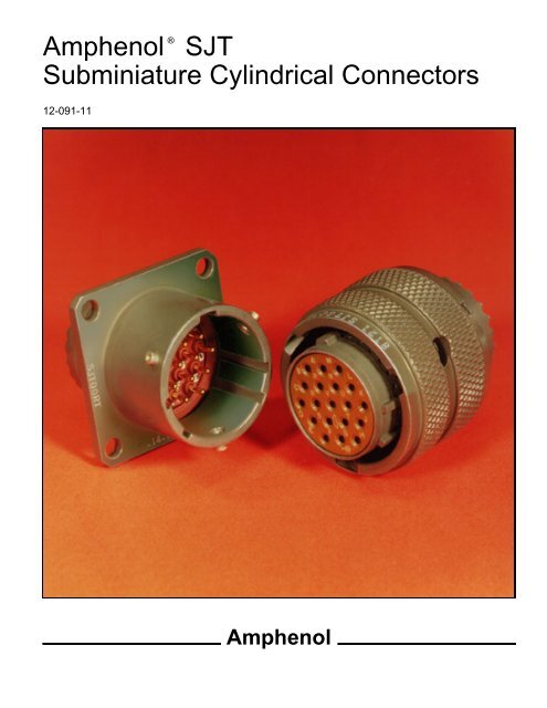
®<strong>Amphenol</strong> <strong>SJT</strong>100% scoop-proof junior tri-locksubminiature cylindrical<strong>Amphenol</strong> ® <strong>SJT</strong> connectors combine unique design featuresof the scoop-proof LJT series within standard mountingdimensions of JT types. Available in a wide range ofshell sizes, finishes, insert arrangements and accessories,the <strong>SJT</strong> features:wall mounting receptaclestraight plugjam nut receptacle1• 100% scoop-proof design – basic MIL-DTL-38999 Series I*lengths• Standard mounting dimensions – MIL-DTL-38999, SeriesIII** dimensions• Compliance with <strong>Europe</strong>an Specifications – PAN6433-2,LN29729, BS9522F0012, VG96912ComponentsShell components are aluminum. Standard plating on shellcomponents is cadmium over nickel with many optional finishesavailable. Hermetic seal receptacles are available in carbonsteel or stainless steel shells. Dependable 5 key/keyway shellpolarization with bayonet lock coupling is incorporated to aidand assure positive mating.Insert material is a high temperature, rigid dielectric polymerproviding excellent electrical characteristics. Contrasting letteror number designations are used on insert faces.A fluorinated silicone interfacial seal is featured on the matingface of pin inserts, assuring complete electrical isolation of pinswhen connector halves are mated. In addition, a main joint gasketis installed in the receptacles for moisture sealing betweenconnector halves.Serrated and threaded shells with moisture sealing pilot forback shells accept a wide range of accessories.ContactsStandard contact plating is 50 micro inches minimum gold.Power contacts are available in sizes 10, 12, 16, 20, 22, 22Mand 22D. Size 8 and 12 twinax contacts are also available. Concentrictwinax contact information is available in <strong>Amphenol</strong> brochureSL-388. All socket contacts are probe proof. Rearinsertable/rear release crimp contacts are standard in <strong>SJT</strong> connectors.High density insert patterns are available.Coaxial contacts are available in sizes 8, 12 and 16 to acommodatea wide range of coaxial cables. For complete informationsee Coaxial Contact catalog 12-130.Optional FeaturesSpecial adaptations of the <strong>SJT</strong> are available for hermetic andhigh temperature applications. The <strong>SJT</strong>S high temperature connectoris rated at 392°F. <strong>SJT</strong> hermetic receptacles aredescribed on pages 14 and 15.SpecialsSpecial types are available, such as connectors less contacts,and circular rack and panel connectors with solderless wrapcontacts.A complete listing of connector types, shell styles and serviceclasses appears on page 20, How to Order. For further informationon special application requirements, contact Sidney N.Y.*MIL-DTL-38999 Series I supersedes MIL-C-38999 Series I.**MIL-DTL-38999 Series III supersedes MIL-C-38999 Series III.
<strong>SJT</strong>specifications, alternate rotationsTest CurrentMaximum MaximumContactSize Standard HermeticMillivoltDrop Crimp*Millivolt DropHermetic22M 3 2 45 6022D 5 3 73 8522 5 3 73 8520 7.5 5 55 6016 13 10 49 8512 23 17 42 8510 Power 33 NA 33 NA* When using silver plated wireCONTACT RATINGSERVICE RATING**ServiceSuggested Operating Voltage(Sea Level)Test VoltageTest VoltageTest VoltageTest VoltageRatingAC(RMS)DC(Sea Level)50,000 Ft.70,000 Ft.110,000 Ft.M 400 550 1300 VRMS 550 VRMS 350 VRMS 200 VRMSN 300 450 1000 VRMS 400 VRMS 260 VRMS 200 VRMSI 600 850 1800 VRMS 600 VRMS 400 VRMS 200 VRMSII 900 1250 2300 VRMS 800 VRMS 500 VRMS 200 VRMS** Please note that the establishment of electrical safety factors is left entirely in the designer’s hands, since he is in the best possible position to know what peak voltage,switching surges, transients, etc., can be expected in a particular circuit.FINISH DATAAluminum Shell Components Non-HermeticFinishSuffixIndicated FinishStandard for <strong>SJT</strong> TypesBright Cadmium Plated Nickel Base<strong>SJT</strong>/<strong>SJT</strong>GAnodic Coating (Alumilite) (005)Chromate Treated (Iridite 14-2) (011)Olive Drab Cadmium Plate Nickel Base (014)Electroless Nickel Coating (023)Hermetic <strong>Connectors</strong>Carbon Steel Shell, Tin Plated Shell and Contacts <strong>SJT</strong>( )YStainless Steel Shell, Gold Plated ContactsConsult Sidney, NYCrimp Well DataContactSizeWellDiameterMin.Well Depth22M .028 ±.001 .14122D .0345 ±.0010 .14122 .0365 ±.0010 .14120 .047 ±.001 .20916 .067 ±.001 .20912 .100 ±.002 .20910 (Power) .137 ±.002 .355<strong>SJT</strong> ALTERNATE ROTATIONSA plug with a given rotation letter will mate with a receptacle with the samerotation letter. The AB angle for a given connector is the same whether itcontains pins or sockets. Inserts are not rotated in conjunction with themaster key/keyway.AB angles shown are viewed from the front face of the connector. A receptacleis shown at right. The angles for the plug are exactly the same, exceptthe direction of rotation is opposite of that shown for the receptacle.Master Key/Keyway RotationAB ANGLE OF ROTATION (Degrees)Shell Size Normal A B C D8 9510 95 81 67 123 10912 95 75 63 127 11514 95 74 61 129 11616 95 77 65 125 11318 95 77 65 125 11320 95 77 65 125 11322 95 80 69 121 11024 95 80 69 121 1102RELATIVE POSSIBLE POSITIONOF ROTATED MASTER KEYWAY(front face of receptacle shown)
<strong>SJT</strong>insert availability and identificationContact SizeShellSizeCrimp Hermetics*Class YServiceRatingTotalContacts22D 22M 22 20 16 12 12(Coax)10(Power)8(Coax)8†††(Twinax)8-6 X M 6 68-35 X M 6 68-44 X M 4 48-98 X I 3 310-2 I 2 210-4 I 4 410-5 I 5 510-13 X M 13 1310-35 X M 13 1310-98 X I 6 612-4 X I 4 412-8 X I 8 812-22 X M 22 2212-35 X M 22 2212-98 X X I 10 1014-5 X II 5 514-15 X I 15 14 114-18 X I 18 1814-19 X X I 19 1914-35 X X M 37 3714-37 X X M 37 3714-97 I 12 8 416-2 M 39 38 1**16-6 X I 6 616-8 X II 8 816-13 I 13 1316-26 X I 26 2616-35 X M 55 5516-42 M 42 4216-55 X M 55 5516-99 X X I 23 21 218-11 X II 11 1118-32 X I 32 3218-35 X X M 66 6618-66 X X M 66 6620-1 X X M 79 7920-2 X M 65 6520-11 I 11 1120-16 X II 16 1620-35 X X M 79 7920-39 X I 39 37 220-41 X I 41 4120-75 M 4 4††20-79 II 19 17 2†22-1 X X M 100 10022-2 X M 85 8522-21 X II 21 2122-35 X X M 100 10022-53 X I 53 5324-1 X M 128 12824-2 X M 100 10024-4 X I 56 48 824-7 M 99 97 2**24-11 N 11 2 924-19 I 19 1924-20 N 30 10 13*** 4 324-24 X I 24 12 1224-29 X I 29 2924-35 X M 128 12824-37 I 37 3724-43 I 43 23 2024-46 I 46 40 4 2††24-61 X I 61 61 not tooled for 02-RE* Pin inserts only (contact Sidney, NY for socket availability).** twinax contacts for MIL-C-17/176-00002 cable.*** Two size 16 contacts dedicated to fiber optics. Consult Sidney, NYor Catalog Section 12-352 for fiber optic information.3† must be ordered separately†† Coax Contacts for RG180 or RG195 cable.††† Size 8 Coax and Twinax are interchangeable.For availability of size 12 twinax contacts, consult<strong>Amphenol</strong>, Sidney, NY
<strong>SJT</strong>insert arrangementsfront face of pin inserts illustratedInsert Arrangement 8-6 8-35 8-44 8-98 10-2Service Rating M M M I INumber of Contacts 6 6 4 3 2Contact Size 22M 22D 22 20 16Insert Arrangement 10-4 10-5 10-13 10-35 10-98Service Rating I I M M INumber of Contacts 4 5 13 13 6Contact Size 20 20 22M 22D 20Insert Arrangement 12-4 12-8 12-22 12-35 12-98Service Rating I I M M INumber of Contacts 4 8 22 22 10Contact Size 16 20 22M 22D 20Insert Arrangement 14-5 14-15 14-18 14-19 14-35Service Rating II I I I MNumber of Contacts 5 14 1 18 19 37Contact Size 16 20 16 20 20 22D4CONTACT LEGEND 8 10 12 16 20 22 22M 22D
<strong>SJT</strong>insert arrangementsfront face of pin inserts illustratedInsert Arrangement 14-37 14-97 16-2 16-6Service Rating M I M INumber of Contacts 37 8 4 38 1 6Contact Size 22M 20 16 22D 8 Twinax 12Insert Arrangement 16-8 16-13 16-26 16-35Service Rating II I I MNumber of Contacts 8 13 26 55Contact Size 16 16 20 22DInsert Arrangement 16-42 16-55 16-99 18-11Service Rating M M I IINumber of Contacts 42 55 21 2 11Contact Size 22 22M 20 16 16Insert Arrangement 18-32 18-35 18-66 20-1Service Rating I M M MNumber of Contacts 32 66 66 79Contact Size 20 22D 22M 22M5
<strong>SJT</strong>insert arrangementsfront face of pin inserts illustratedInsert Arrangement 20-2 20-11 20-16 20-35Service Rating M I II MNumber of Contacts 65 11 16 79Contact Size 22 12 16 22DInsert Arrangement 20-39 20-41 20-75 20-79Service Rating I I M IINumber of Contacts 37 2 41 4 17 2Contact Size 20 16 20 8 Coax †† 22 8 Coax †Insert Arrangements 22-1 22-2 22-21 22-35Service Rating M M II MNumber of Contacts 100 85 21 100Contact Size 22M 22 16 22D† must be ordered separately†† coax contacts for RG180 or RG195 cable6CONTACT LEGEND 8 10 12 16 20 22 22M 22D
<strong>SJT</strong>insert arrangementsfront face of pin inserts illustratedInsert Arrangement 22-53 24-1 24-2Service Rating I M MNumber of Contacts 53 128 100Contact Size 20 22M 22Insert Arrangement 24-4 24-7 24-11Service Rating I M NNumber of Contacts 48 8 97 2 2 9Contact Size 20 16 22D 8 Twinax 20 10 PowerInsert Arrangement 24-19 24-20 24-24Service Rating I N INumber of Contacts 19 10 13 3 4 16 12Contact Size 12 20 16 8 Twinax 12 Coax 16 127
<strong>SJT</strong>insert arrangementsfront face of pin inserts illustratedInsert Arrangement 24-29 24-35 24-37Service Rating I M INumber of Contacts 29 128 37Contact Size 16 22D 16Insert Arrangement 24-43 24-46 24-61Service Rating I I INumber of Contacts 23 20 40 4 2 61Contact Size 20 16 20 16 8 Coax †† 20†† coax contacts for RG180 or RG195 cable8CONTACT LEGEND 8 10 12 16 20 22 22M 22D
<strong>SJT</strong>00RT– crimpwall mounting receptacle*<strong>SJT</strong>00RT-XX-XXX* To complete order number, see page 20** Standard wall mount may be back panel mounted where panel thickness does notexceed these dimensions. For thicker panel applications, <strong>SJT</strong>P00RT should be used,page 10.ShellSizeLMaxM+.000–.005All dimensions for reference only.R(TP)S±.016T±.005Class 2AUNEF (Plated)V Thread ModifiedModifiedMajor Dia.N+.001–.0058 .500 .632 .594 .812 .120 .4375-28 .421 – .417 .473 .11710 .500 .632 .719 .938 .120 .5625-24 .542 – .538 .590 .11712 .500 .632 .812 1.031 .120 .6875-24 .667 – .663 .750 .11714 .500 .632 .906 1.125 .120 .8125-20 .791 – .787 .875 .11716 .500 .632 .969 1.219 .120 .9375-20 .916 – .912 1.000 .11718 .500 .632 1.062 1.312 .120 1.0625-18 1.034 – 1.030 1.125 .11720 .500 .602 1.156 1.438 .120 1.1875-18 1.158 – 1.154 1.250 .08722 .500 .602 1.250 1.562 .120 1.3125-18 1.283 – 1.279 1.375 .08724 .550 .602 1.375 1.688 .147 1.4375-18 1.408 – 1.404 1.500 .055P**Max9
<strong>SJT</strong>P00RT – crimpwall mounting receptacle (back panel mounting)*<strong>SJT</strong>P00RT-XX-XXX* To complete order number, see page 20ShellSizeF+.000–.005K+.006–.000All dimensions for reference only.LMax.M+.000–.005R(TP)S+.011–.010T±.005Z±.031V ThreadClass 2A(Plated) UNEFPDia.+.001–.0058 .609 .945 .539 .860 .594 .812 .120 .062 .4375-28 .516 .812 .34510 .609 .945 .539 .860 .719 .938 .120 .062 .5625-24 .633 .812 .34512 .609 .945 .539 .860 .812 1.031 .120 .062 .6875-24 .802 .812 .34514 .609 .945 .539 .860 .906 1.125 .120 .062 .8125-20 .927 .812 .34516 .609 .945 .539 .860 .969 1.219 .120 .062 .9375-20 1.052 .812 .34518 .609 .945 .539 .860 1.062 1.312 .120 .062 1.0625-18 1.177 .812 .34520 .609 .945 .539 .860 1.156 1.438 .120 .062 1.1875-18 1.302 .812 .34522 .609 .945 .539 .860 1.250 1.562 .120 .062 1.3125-18 1.427 .812 .34524 .750 1.085 .493 1.000 1.375 1.688 .147 .078 1.4375-18 1.552 .781 .452WMax.GMax.10
<strong>SJT</strong>P02RE – crimpbox mounting receptacle (back panel mounting)*<strong>SJT</strong>P02RE-XX-XXX* To complete order number, see page 20ShellSizeF+.000–.005K+.006–.000All dimensions for reference only.M+.000–.005R(TP)S+.011–.010T±.005Z±.031PDia.+.001–.005KKDia.+.005–.0028 .609 .945 .860 .594 .812 .120 .062 .516 .417 .345GMax.10 .609 .945 .860 .719 .938 .120 .062 .633 .538 .34512 .609 .945 .860 .812 1.031 .120 .062 .802 .663 .34514 .609 .945 .860 .906 1.125 .120 .062 .927 .787 .34516 .609 .945 .860 .969 1.219 .120 .062 1.052 .912 .34518 .609 .945 .860 1.062 1.312 .120 .062 1.177 1.030 .34520 .609 .945 .860 1.156 1.438 .120 .062 1.302 1.154 .34522 .609 .945 .860 1.250 1.562 .120 .062 1.427 1.279 .34524 .750 1.085 1.000 1.375 1.688 .147 .078 1.552 1.404 .45211
<strong>SJT</strong>06RT/<strong>SJT</strong>G06RT – crimpstraight plug/straight plug (with grounding fingers)*<strong>SJT</strong>06RT-XX-XXX* To complete order, see page 20*<strong>SJT</strong>G06RT-XX-XXXShellSizeLMaxAll dimensions for reference only.QDia. Max.Class 2AUNEF (Plated)V ThreadModifiedMajor Dia.8 1.219 .734 .4375-28 .421 – .41710 1.219 .844 .5625-24 .542 – .53812 1.219 1.016 .6875-24 .667 – .66314 1.219 1.141 .8125-20 .791 – .78716 1.219 1.265 .9375-20 .916 – .91218 1.219 1.391 1.0625-18 1.034 – 1.03020 1.219 1.500 1.1875-18 1.158 – 1.15422 1.219 1.625 1.3125-18 1.283 – 1.27924 1.258 1.750 1.4375-18 1.408 – 1.40412
<strong>SJT</strong>07RT – crimpjam nut receptacle*<strong>SJT</strong>07RT-XX-XXX• “D” shaped panel cut-out dimensions* To complete order number, see page 20** Oversize threads. Check accessory threads before orderingShellSizeA•+.000–.010HHex+.017–.016All dimensions for reference only.S±.016V ThreadClass 2AUNEF (Plated)R ThreadClass 2AUNEF (Plated)N+.001–.005CMax.T•+.010–.0008 .542 .750 .938 .5625-24 .5625-24 .473 1.078 .57210 .669 .875 1.062 .6875-24 .6875-24 .590 1.203 .69712 .830 1.062 1.250 .8125-20 .8750-20 .750 1.391 .88414 .955 1.188 1.375 .9375-20 1.0000-20 .875 1.515 1.00716 1.084 1.312 1.500 1.0625-18 1.1250-18 1.000 1.641 1.13418 1.208 1.438 1.625 1.1875-18 1.2500-18 1.125 1.766 1.25920 1.333 1.562 1.812 1.3125-18 1.3750-18 1.250 1.953 1.38422 1.459 1.688 1.938 1.4375-18 1.5000-18 1.375 2.078 1.50724 1.580 1.812 2.062 1.4375-18 1.6250-18 1.500 2.203 1.63413
<strong>SJT</strong>IY – hermeticsolder mounting receptacle*<strong>SJT</strong>IY-XX-XXX* To complete order, see page 20ShellSizeL+.011–.000All dimensions for reference only.M+.006–.005GDia.+.011–.010KDia.+.001–.005N+.001–.0058 .789 .125 .687 .562 .47310 .789 .125 .797 .672 .59012 .789 .125 .906 .781 .75014 .789 .125 1.031 .906 .87516 .789 .125 1.156 1.031 1.00018 .789 .125 1.281 1.156 1.12520 .789 .125 1.375 1.250 1.25022 .821 .156 1.500 1.375 1.37524 .821 .156 1.625 1.500 1.50014
<strong>SJT</strong>07Y – hermeticjam nut receptacle*<strong>SJT</strong>07Y-XX-XXX• “D” shaped panel cut-out dimensions* To complete order number, see page 20ShellSizeN+.001–.005CMax.All dimensions for reference only.A•+.000–.010LMax.HHex+.017–.016S±.016KK+.011–.000RRThreadClass 2AUNEF (Plated)T•+.010–.0008 .473 1.078 .542 .297 .750 .938 .642 .5625-24 .57210 .590 1.203 .669 .297 .875 1.062 .766 .6875-24 .69712 .750 1.391 .830 .297 1.062 1.250 .892 .8750-20 .88414 .875 1.515 .955 .297 1.188 1.375 1.018 1.0000-20 1.00716 1.000 1.641 1.084 .297 1.312 1.500 1.142 1.1250-18 1.13418 1.125 1.766 1.208 .328 1.438 1.625 1.268 1.2500-18 1.25920 1.250 1.953 1.333 .328 1.562 1.812 1.392 1.3750-18 1.38422 1.375 2.078 1.459 .328 1.688 1.938 1.518 1.5000-18 1.50724 1.500 2.203 1.580 .328 1.812 2.062 1.642 1.6250-18 1.63415
<strong>SJT</strong>contacts, sealing plugs, plastic protection capsContactSize<strong>SJT</strong>PinsCONTACTS & SEALING PLUGS<strong>SJT</strong>SocketsSealingPlugs8 (Coax) 21-33102-21** 21-33101-21** 10-482099-88 (Twinax) 21-33190-529† 21-33191-530† 10-482099-810 (Power) 10-251415-105 10-407035-105 Not Available12 10-251415-12H 10-407035-125 10-405996-12 Yellow16 10-251415-165 10-407035-165 10-405996-16 Blue20 10-251415-20510-407035-20510-497403-205††10-405996-20 Red22* 10-251415-225 10-407035-225 10-405996-22 Black22M* 10-251415-235 10-407035-235 10-405996-22 Black22D 10-251415-725 10-407035-725 10-405996-22 BlackAbove part numbers include standard finish designation – gold plating over suitable underplate in accordance withMIL-C-39029. For other finish variations, consult <strong>Amphenol</strong>, Sidney, NY.* Inactive for new design.** 21-33102-21 and 21-33101-21 are for use with RG180B/U and RG195A/U cable. For other size 8 coax or optionalsizes 12 and 16 coax contacts available for use in <strong>SJT</strong> connectors, see catalog 12-130 or consult <strong>Amphenol</strong>,Sidney, NY.† 21-33190-529 and 21-33191-530 are for use with M17/176-00002 cable.†† Optional design – see slash sheet MS39029.For other contact options available for use in <strong>SJT</strong> connectors, (wire-wrap, thermocouple, fiber optic)consult <strong>Amphenol</strong>, Sidney, NY.PLASTIC PROTECTION CAPSShellSize Plug Receptacle8 10-70500-10 10-70506-10S10 10-70500-14 10-70506-1212 10-70500-16 10-70506-1414 10-70500-18 10-70506-1616 10-70500-20 10-70506-1818 10-70500-22 10-70506-2020 10-70500-24 10-70506-2222 10-70524-1 10-70506-2424 10-70506-28 10-70524-116
<strong>SJT</strong> – accessoriesplug protection cap/receptacle protection capPLUG PROTECTION CAPRECEPTACLE PROTECTION CAP*10-476801-XXX*10-325943-XXX*10-476810-XXX*To complete order number, add shell size and suffixnumber. For example, shell size 10 with bright cadmiumplated nickel base, 10-476810-107.Plug ShellSizeDDia.Max.N Dia.+.001–.0058 .688 .47310 .812 .59012 .969 .75014 1.094 .87516 1.219 1.00018 1.344 1.12520 1.469 1.25022 1.594 1.37524 1.719 1.500*To complete order number, add shell size and suffixnumber. For example, shell size 10 with bright cadmiumplated nickel base, 10-325943-107.ReceptacleShell SizeDDDia. Max.LMax.8 .734 .82810 .844 .82812 1.016 .82814 1.141 .82816 1.265 .82818 1.391 .82820 1.500 .82822 1.625 .82824 1.750 .859FinishBright Cadmium Plated Nickel BaseAnodic Coating (Alumilite)Chromate Treated (Iridite 14-2)Olive Drab Cadmium Plate Nickel BaseElectroless Nickel CoatingSuffixXX7XX5XX0XX9XXGAll dimensions for reference only17
<strong>SJT</strong> – accessoriesdummy receptacle, cable clampDUMMY RECEPTACLEFinishBright Cadmium Plated Nickel BaseAnodic Coating (Alumilite)Chromate Treated (Iridite 14-2)Olive Drab Cadmium Plate Nickel BaseElectroless Nickel CoatingSuffixXX7XX5XX0XX9XXG* To complete order number, add shell size and suffix number. For example,shell size 10 with bright cadmium plated nickel base, 10-476807-107.*10-476807-XXXDummy ReceptacleShell SizeAll dimensions for reference onlyDDia. Max.LMax.8 .734 .82810 .844 .82812 1.016 .82814 1.141 .82816 1.265 .82818 1.391 .82820 1.500 .82822 1.625 .82824 1.750 .859CABLE CLAMPFinishBright Cadmium Plated Nickel BaseAnodic Coating (Alumilite)Chromate Treated (Iridite 14-2)Olive Drab Cadmium Plate Nickel BaseElectroless Nickel CoatingSuffixXX7XX5XX0XX9XXG* To complete order number, add shell size and suffix number. For example,shell size 10 with bright cadmium plated nickel base, 10-476808-107.*10-476808-XXXCableClampShellSizeADia.+.010–.025BDia.+.000–.011All dimensions for reference onlyLMax.YThreadClass 2BUNEF (Plated)GGMax.8 .125 .250 .922 .4375-28 .77510 .188 .312 .922 .5625-24 .83712 .312 .438 .922 .6875-24 .96314 .375 .562 1.172 .8125-20 1.08716 .500 .625 1.172 .9375-20 1.15018 .625 .750 1.172 1.0625-18 1.40020 .625 .750 1.172 1.1875-18 1.40022 .750 .938 1.297 1.3125-18 1.58724 .800 1.000 1.297 1.4375-18 1.68118
<strong>SJT</strong>application toolsThe following data includes information pertaining to the applicationtools which have been established for crimping, inserting, andremoving contacts incorporated in the <strong>SJT</strong>.For additional information on coaxial contact tools, see catalog 12-130.ContactSize/TypeCrimpingToolTurret Dieor Positioner12 Pinand Socket M22520/1-01 M22520/1-0416 Pin andSocket20 PinandSocket22, 22D, 22MPin22, 22D, 22MSocket (LJT-R)M22520/1-01M22520/7-01M22520/1-01M22520/2-01M22520/7-01M22520/2-01M22520/7-01M22520/2-01M22520/7-01M22520/1-04M22520/7-04M22520/1-04M22520/2-10M22520/7-08M22520/2-09M22520/7-07M22520/2-07M22520/7-058 Twinax CenterPin and Socket M22520/2-01 M22520/2-378 Twinax IntermediateOuter Pin & Socket M22520/5-01 M22520/5-200CRIMPING TOOLSWhere 2 or 3 tools are listed for a contact size, only one tool and its die or positioner are required to crimp the contact.The above crimping tools and positioners are available from the approved tool manufacturer.UseWithContactSizePlastic ToolsINSERTION TOOLSAll crimping tools included are the “full cycling” type and when usedas specified in the installation instructions (L-624) covering the <strong>SJT</strong>series connectors, will provide reliable crimped wire to contact terminations.There is a possibility of additional crimping tools otherthan those included being available at present or in the future forthis specific application.ContactSize/TypeCrimpingToolTurret Dieor Positioner8 Coaxial InnerPin and Socket M22520/2-01 M22520/2-318CoaxialOuterPinandSocketMetal ToolsAngle TypeMSProprietaryPart NumberPart NumberM22520/5-01M22520/5-01M22520/5-05Die Closure BM22520/5-41Die Closure BM22520/10-07Die Closure BM22520/10-0116 Coaxial InnerPin and Socket M22520/2-01 M22520/2-3516 Coaxial OuterPin and Socket M22520/4-01 M22520/4-0212 Coaxial InnerPin and Socket M22520/2-01 M22520/2-3412 Coaxial OuterPin and Socket M22520/31-01 M22520/31-0210 (Power) *** ***Straight TypeProprietaryPart NumberMSPart Number ColorColor10 (Power) M81969/14-05* Gray/(White) M81969/8-11 † † Green12 M81969/14-04* Yellow/(White) M81969/8-09 11-8674-12 11-8794-12 Yellow16 M81969/14-03* Blue/(White) M81969/8-07 11-8674-16 11-8794-16 Blue20 M81969/14-10* Red/(Orange) M81969/8-05 11-8674-20 11-8794-20 Red22 M81969/14-09* Brown/(White) M81969/8-03 11-8674-22 11-8794-22 Brown22D, 22M M81969/14-01* Green/(White) M81969/8-01 11-8674-24 11-8794-22 Brown8 Coaxial None Required8 Twinax None M81969/46-06** None RedUseWithContactSizePlastic ToolsREMOVAL TOOLSFor UnwiredContactsProprietaryPart NumberMetal ToolsAngle TypeStraight TypeMSPart NumberColorCodeMSPart NumberProprietaryPart NumberProprietaryPart NumberColorCode10 (Power) M81969/14-05* (Green)/White † M81969/8-12 † † Green/White12 M81969/14-04* (Yellow)/White 11-10050-11 M81969/8-10 11-8675-12 11-8795-12 Yellow/White16 M81969/14-03* (Blue)/White 11-10050-10 M81969/8-08 11-8675-16 11-8795-16 Blue/White20 M81969/14-10* Orange 11-10050-9 M81969/8-06 11-8675-20 11-8795-20 Red/White22 M81969/14-09* (Brown)/White 11-10050-8 M81969/8-04 11-8675-22 11-8795-22 Brown/White22D, 22M M81969/14-01* (Green)/White 11-10050-7 M81969/8-02 11-8675-24 11-8795-24 Green/White8 Coaxial M81969/14-12 Green None None 11-9170 DRK264-8†† N/A8 Twinax M81969/14-12 Green None M81969/46-12** 11-9170 N/A N/AThe M81969/8, 11-8674, 11-8675, and 11-8794 metal contact insertion and removal tools will accommodate wires havingthe maximum outside diameter as follows: Contact size 12–.155, 16–.109, 20–.077, 22, 22D, 22M–.050. When wire diametersexceed those specified, the plastic tools must be used.* Double ended insertion/removal tool.** Twinax insertion tools are available only in a straight type, metal version.*** For size 10 power contact application tools, consult <strong>Amphenol</strong>, Sidney, NY.19† To be determined.†† Contact Daniels Manufacturing Co. for availability.
<strong>SJT</strong>how to orderPART NUMBERTo more easily illustrate ordering procedure, part number<strong>SJT</strong>00RT-18-66PA( ) is shown as follows:<strong>SJT</strong> 00 RT – 18 – 66 P A ( )1 2 3 4 5 6 7 8See code below:1. Connector Type:<strong>SJT</strong> designates standard scoop-proof Junior Tri-Lock Connector<strong>SJT</strong>S designates high temperature connector<strong>SJT</strong>G designates plug with grounding fingers<strong>SJT</strong>P designates back panel mounted2. Shell Style:00 designates wall mount receptacle06 designates straight plug07 designates jam nut receptacleI designates solder mount receptacle – hermetic3. Service Class:“Y” for hermetic applications. . . fused compression glass sealedinserts. Leakage rate less than 1.0 x 10 -6 cc/sec. at 15 psi differential;with interfacial seal.“RT” for environmental applications – supplied without rear accessories.Design provides serrations on rear threads of shells with moisturesealing pilot for back shells.For additional information defining complete description of serviceclass, consult <strong>Amphenol</strong>, Sidney, NY.4. <strong>SJT</strong> shell sizes available from 8 through 24.5. 18-66 designates insert arrangement. Refer to pages 3 through 8 forinsert pattern availability.6. “P” designates pin contacts; “S” for socket contacts.7. “A” designates alternate keying. Other basic rotations are “B”, “C” and“D”. No letter required for normal (no rotation) position. (see page 2)8. Finish variation suffix. (Page 2).<strong>Amphenol</strong> ® Federal Vendor Identification/FSCM7782020


