YCCD-CU
YCCD-CU YCCD-CU
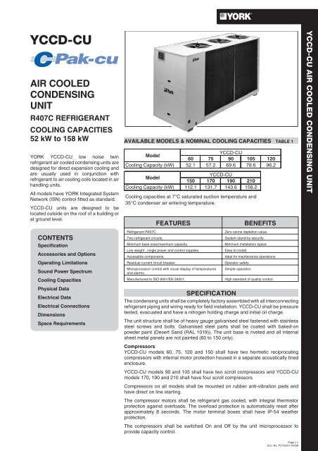
YCCD-CUAIR COOLEDCONDENSINGUNITR407C REFRIGERANTCOOLING CAPACITIES52 kW to 158 kWYORK YCCD-CU low noise twinrefrigerant air cooled condensing units aredesigned for direct expansion cooling andare usually used in conjunction withrefrigerant to air cooling coils located in airhandling units.All models have YORK Integrated SystemNetwork (ISN) control fitted as standard.YCCD-CU units are designed to belocated outside on the roof of a building orat ground level.CONTENTSSpecificationAccessories and OptionsOperating LimitationsSound Power SpectrumCooling CapacitiesPhysical DataElectrical DataElectrical ConnectionsDimensionsSpace RequirementsAVAILABLE MODELS & NOMINAL COOLING CAPACITIES TABLE 1YCCD-CUModel60 75 90 105 120Cooling Capacity (kW) 52.1 57.2 69.6 78.6 96.2YCCD-CUModel150 170 190 210Cooling Capacity (kW) 112.1 131.7 143.6 158.2Cooling capacities at 7°C saturated suction temperature and35°C condenser air entering temperature.FEATURESRefrigerant R407C.Two refrigerant circuits.Minimum base area/maximum capacity.Low weight , single power and control supplies.Accessible components.Residual current circuit breaker.Microprocessor control with visual display of temperaturesand alarms.Manufactured to ISO 9001/EN 29001.BENEFITSZero ozone depletion value.System stand-by security.Minimum installation space.Easy to install.Ideal for maintenance operationsOperator safety.Simple operation.High standard of quality control.SPECIFICATIONThe condensing units shall be completely factory assembled with all interconnectingrefrigerant piping and wiring ready for field installation. YCCD-CU shall be pressuretested, evacuated and have a nitrogen holding charge and initial oil charge.The unit structure shall be of heavy gauge galvanised steel fastened with stainlesssteel screws and bolts. Galvanised steel parts shall be coated with baked-onpowder paint (Desert Sand (RAL 1019)). The unit base is riveted and all internalsheet metal panels are not painted (60 to 150 only).CompressorsYCCD-CU models 60, 75, 120 and 150 shall have two hermetic reciprocatingcompressors with internal motor protection housed in a separate acoustically linedenclosure.YCCD-CU models 90 and 105 shall have two scroll compressors and YCCD-CUmodels 170, 190 and 210 shall have four scroll compressors.Compressors on all models shall be mounted on rubber anti-vibration pads andhave direct on line starting.The compressor motors shall be refrigerant gas cooled, with integral thermistorprotection against overloads. The overload protection is automatically reset afterapproximately 8 seconds. The motor terminal boxes shall have IP-54 weatherprotection.The compressors shall be switched On and Off by the unit microprocessor toprovide capacity control.YCCD-CU AIR COOLED CONDENSING UNITPage J.1Doc. No. PC152/01.04/GB
- Page 2 and 3: Refrigerant CircuitsTwo complete re
- Page 4 and 5: TABLE 4YCCD-CU COOLING CAPACITIESYC
- Page 6 and 7: TABLE 6ELECTRICAL DATAYCCD-CUSystem
- Page 8 and 9: DIMENSIONS - YCCD-CU MODELS 60, 75,
- Page 10 and 11: DIMENSIONS - YCCD-CU MODELS 170 TO
- Page 12: Page J.12Doc. No. PC152/01.04/GBNOT
<strong>YCCD</strong>-<strong>CU</strong>AIR COOLEDCONDENSINGUNITR407C REFRIGERANTCOOLING CAPACITIES52 kW to 158 kWYORK <strong>YCCD</strong>-<strong>CU</strong> low noise twinrefrigerant air cooled condensing units aredesigned for direct expansion cooling andare usually used in conjunction withrefrigerant to air cooling coils located in airhandling units.All models have YORK Integrated SystemNetwork (ISN) control fitted as standard.<strong>YCCD</strong>-<strong>CU</strong> units are designed to belocated outside on the roof of a building orat ground level.CONTENTSSpecificationAccessories and OptionsOperating LimitationsSound Power SpectrumCooling CapacitiesPhysical DataElectrical DataElectrical ConnectionsDimensionsSpace RequirementsAVAILABLE MODELS & NOMINAL COOLING CAPACITIES TABLE 1<strong>YCCD</strong>-<strong>CU</strong>Model60 75 90 105 120Cooling Capacity (kW) 52.1 57.2 69.6 78.6 96.2<strong>YCCD</strong>-<strong>CU</strong>Model150 170 190 210Cooling Capacity (kW) 112.1 131.7 143.6 158.2Cooling capacities at 7°C saturated suction temperature and35°C condenser air entering temperature.FEATURESRefrigerant R407C.Two refrigerant circuits.Minimum base area/maximum capacity.Low weight , single power and control supplies.Accessible components.Residual current circuit breaker.Microprocessor control with visual display of temperaturesand alarms.Manufactured to ISO 9001/EN 29001.BENEFITSZero ozone depletion value.System stand-by security.Minimum installation space.Easy to install.Ideal for maintenance operationsOperator safety.Simple operation.High standard of quality control.SPECIFICATIONThe condensing units shall be completely factory assembled with all interconnectingrefrigerant piping and wiring ready for field installation. <strong>YCCD</strong>-<strong>CU</strong> shall be pressuretested, evacuated and have a nitrogen holding charge and initial oil charge.The unit structure shall be of heavy gauge galvanised steel fastened with stainlesssteel screws and bolts. Galvanised steel parts shall be coated with baked-onpowder paint (Desert Sand (RAL 1019)). The unit base is riveted and all internalsheet metal panels are not painted (60 to 150 only).Compressors<strong>YCCD</strong>-<strong>CU</strong> models 60, 75, 120 and 150 shall have two hermetic reciprocatingcompressors with internal motor protection housed in a separate acoustically linedenclosure.<strong>YCCD</strong>-<strong>CU</strong> models 90 and 105 shall have two scroll compressors and <strong>YCCD</strong>-<strong>CU</strong>models 170, 190 and 210 shall have four scroll compressors.Compressors on all models shall be mounted on rubber anti-vibration pads andhave direct on line starting.The compressor motors shall be refrigerant gas cooled, with integral thermistorprotection against overloads. The overload protection is automatically reset afterapproximately 8 seconds. The motor terminal boxes shall have IP-54 weatherprotection.The compressors shall be switched On and Off by the unit microprocessor toprovide capacity control.<strong>YCCD</strong>-<strong>CU</strong> AIR COOLED CONDENSING UNITPage J.1Doc. No. PC152/01.04/GB
Refrigerant CircuitsTwo complete refrigerant circuits of ACR copper, with brazedjoints shall be provided on each unit. Refrigerant circuits shallinclude: service valves for refrigerant charging, discharge,suction and liquid line isolating (ball) valves and fusible plugs forover-pressure protection.Transducers and pressure switches shall be included on thehigh pressure circuits of all <strong>YCCD</strong>-<strong>CU</strong> models. Low pressuretransducers shall be provided on the low pressure circuits of allmodels.Air Cooled CondensersThe condenser coils shall be seamless copper tubes, arrangedin staggered rows, mechanically expanded into corrugatedaluminium fins. Integral sub-cooling will be included. Designworking pressure of the coils shall be 28 bar g.All <strong>YCCD</strong>-<strong>CU</strong> models shall have a stepless fan speed controllerfitted as standard, which operates on the basis of condensingpressure. Operation is possible down to -18°C with the ISNcontrol system.The condenser fans shall be direct drive with aluminium aerofoilblades. Each fan will have a painted galvanised steel protectionguard. The totally enclosed fan motors shall have IP-54 weatherprotection and thermocontact protection embedded in theirwindings.Power and Control PanelAll controls and motor starting equipment necessary for full unitoperation shall be factory wired and tested.Power and control components are accessed via individualdoors on <strong>YCCD</strong>-<strong>CU</strong> models 60 to150.The power compartment shall have a door interlocked isolatorand shall contain compressor and fan contactors, fuses andsupply protection.The control compartment shall contain the YORK IntegratedSystem Network YORK ISN control. The control will offerBuilding Management System (BMS) communication anddisplay and print of unit operational and history data.MillenniumTMDisplay/PrintOPER DATAPRINTHISTORYSTATUSThe panel shall contain:Control CenterSYS 1 COMP RUNNI NGSYS 2 COMP RUNNI NGEntryENTER/ADVONSetpointsOFFCOOLINGSETPOINTSSCHEDULE/ADVANCE DAYPROGRAMISN Millennium Control Center PanelUnitOPTIONS• A 40 character Liquid Crystal Display (LCD) with LightEmitting Diode (LED) back lighting for outdoor viewing.• A Colour coded 12-button keypad.• Customer terminal block for control inputs.CLOCKThe microprocessor control will include:Status Key for display of:• Status of the unit and each refrigerant circuit• System and unit safety fault messagesDisplay/Print Keys for display of:• Ambient air temperature• System pressures (each circuit)• Operating hours and starts (each compressor)• Load and unload timers and cooling demand• Condenser fan statusPrint calls up to the liquid crystal display:• Operating data for the systems• History of fault shutdown data for up to the last six faultshutdown conditionsAn RS-232 port, in conjunction with this press-to-print button, isprovided to allow hard copy print-outs via a separate printer.Entry Keys• To program and modify system valuesSetpoints Keys for programming:• Set daily schedule/holiday for start/stop• Manual override for servicing• Cut-outs for low and high ambient temperature, highdischarge pressure and low suction pressure• Number of compressors and anti-recycle timer (compressorstart cycle time)Unit Keys• To set time and unit optionsUnit ON/OFF switch• To activate or deactivate the unitThe microprocessor control system is capable of displaying thefollowing:• Low ambient temperature cutout setting• Ambient air temperature• Metric or Imperial data• Discharge and suction pressure cutout settings• System suction pressures• System discharge pressures• Anti-recycle timer status• Anti-coincident system start timer condition• Compressor run status• Day, date and time• Daily start/stop times• Holiday status• Automatic or manual system lead/lag control• Lead system definition• Compressor starts & operating hours (each compressor)• Status of fan operation• Run permissive status• Number of compressors running• Load & unload timer statusThe operating program will be stored in non-volatile memory(EPROM) to eliminate chiller failure due to AC powerfailure/battery discharge. Programmed setpoints shall beretained in lithium battery backed RTC memory.Page J.2Doc. No. PC152/01.04/GB
High Pressure FansAlternative fans suitable for external static pressures up to80 Pa.Anti-vibration MountsOpen spring isolator mounts with fixing down holes, suppliedloose for field installation.ACCESSORIES AND OPTIONSCondenser Coil GuardsPainted galvanised steel wire guards mounted on the exterior ofthe unit.Condenser Coil ProtectionCopper fins, Gold epoxy coated aluminium fins - for corrosionresistance in mild seashore locations (Acetic acid spray testASTM 287: 1500 hours).OPERATING LIMITATIONS TABLE 2Model<strong>YCCD</strong>-<strong>CU</strong>60 75 90 105 120 150 170 190 210Ambient Air Entering Temperature °C-18to+43°CAmbient Air External Static Pressure Pa 0 Pa (Standard Fans) / 80 Pa High Pressure FansMaximum Saturated Suction Temperature °C 12 12 12 12Minimum Capacity Step % 5020 25Power Supply Voltage (400 ± 10%)V400 V, 3 Ø, 50 Hz (nominal)SOUND POWER LEVELS (FREQUENCY ANALYSIS (SPECTRUM)) TABLE 3ModelFREQUENCY (Hz)Total<strong>YCCD</strong>-<strong>CU</strong> 125 250 500 1000 2000 4000 8000 dB(A)60 86 84 83 82 80 70 59 8775 86 84 83 82 80 70 59 8790 87 85 84 83 81 71 60 88105 88 86 85 84 82 72 61 89120 89 87 86 85 83 73 62 90150 89 87 86 85 83 73 62 90170 86 90 87 87 85 81 72 93190/210 87 91 88 88 86 82 73 94Tolerance±2dB(A)Sound levels are at fully loaded conditions. Sound power level values refer to ISO standard 3744 and Eurovent 8/1Page J.3Doc. No. PC152/01.04/GB
TABLE 4<strong>YCCD</strong>-<strong>CU</strong> COOLING CAPACITIES<strong>YCCD</strong>-<strong>CU</strong> 190 <strong>YCCD</strong>-<strong>CU</strong> 170 <strong>YCCD</strong>-<strong>CU</strong> 150 <strong>YCCD</strong>-<strong>CU</strong> 120 <strong>YCCD</strong>-<strong>CU</strong> 105 <strong>YCCD</strong>-<strong>CU</strong> 90 <strong>YCCD</strong>-<strong>CU</strong> 75 <strong>YCCD</strong>-<strong>CU</strong> 60 Model<strong>YCCD</strong>-<strong>CU</strong> 210SST°CCondenser Entering Air Temperature °C25 30 32 3540 43Cool Power Cool Power Cool Power Cool Power Cool Power Cool PowerkW kW kW kW kW kW kW kW kW kW kW kW0 48.4 16.2 44.3 16.2 42.7 16.4 40.1 16.6 36.5 16.8 33.9 17.22 51.6 16.8 47.4 17.0 45.8 17.2 43.2 17.7 39.1 18.1 37.0 18.74 55.2 17.7 51.0 18.1 49.5 18.3 46.9 18.7 42.7 19.5 40.1 19.97 60.9 18.9 56.2 19.5 54.7 19.9 52.1 20.3 47.9 32.5 45.3 21.910 66.7 20.3 62.0 21.1 60.4 21.5 57.8 21.9 53.1 22.9 51.0 23.512 70.8 21.5 66.1 22.1 64.1 22.3 61.5 22.9 57.3 23.7 54.7 24.30 53.2 19.0 48.6 19.0 46.9 19.2 44.1 19.4 40.1 19.7 37.2 20.22 56.7 19.7 52.1 19.9 50.4 20.2 47.5 20.6 42.9 21.1 40.6 21.84 60.7 20.6 56.1 21.1 54.4 21.3 51.5 21.8 46.9 22.8 44.1 23.27 67.0 22.0 61.8 22.8 60.1 23.2 57.2 23.7 52.6 37.9 49.8 25.610 73.2 23.7 68.1 24.7 66.4 25.1 63.5 25.6 58.4 26.8 56.1 27.512 77.8 25.1 72.7 25.8 70.4 26.1 67.5 26.8 62.9 27.7 60.1 28.40 62.7 21.2 59.2 23.1 57.8 24.0 55.7 25.3 51.5 27.8 49.4 29.42 66.8 21.5 63.3 23.7 61.3 24.5 59.2 25.9 55.0 28.3 52.2 29.94 71.7 22.1 67.5 24.2 65.4 25.0 63.3 26.4 58.5 28.9 56.4 30.57 78.7 22.9 74.5 24.8 72.4 25.9 69.6 27.2 64.7 29.7 62.0 31.310 86.3 23.4 81.4 25.6 79.4 26.7 76.6 28.0 71.0 30.5 68.2 32.112 91.2 24.0 86.3 26.1 84.2 27.2 80.8 28.6 75.2 31.0 72.4 32.90 70.8 24.9 66.8 27.1 65.3 28.1 62.9 29.7 58.2 32.5 55.8 34.42 75.5 25.2 71.6 27.7 69.2 28.7 66.8 30.3 62.1 33.2 59.0 35.14 81.0 25.8 76.3 28.4 73.9 29.3 71.6 30.9 66.1 33.8 63.7 35.77 88.9 26.8 84.2 29.0 81.8 30.3 78.6 31.9 73.1 34.8 70.0 36.710 97.5 27.4 92.0 30.0 89.7 31.2 86.5 32.8 80.2 35.7 77.1 37.612 103.0 28.1 97.5 30.6 95.2 31.9 91.2 33.5 84.9 36.3 81.8 38.60 89.4 30.9 81.8 30.9 78.9 31.3 74.1 31.7 67.3 32.1 62.5 32.82 95.2 32.1 87.5 32.4 84.6 32.8 79.8 33.6 72.1 34.4 68.3 35.54 102.0 33.6 94.3 34.4 91.4 34.8 86.6 35.5 78.9 37.1 74.1 37.87 112.5 35.9 103.9 37.1 101.0 37.8 96.2 38.6 88.5 61.8 83.7 41.710 123.1 38.6 114.5 40.2 111.6 40.9 106.8 41.7 98.1 43.6 94.3 44.812 130.8 40.9 122.1 42.1 118.3 42.5 113.5 43.6 105.8 45.2 101.0 46.30 104.3 38.3 95.3 38.3 92.0 38.8 86.3 39.3 78.5 39.8 72.9 40.72 111.0 39.8 102.0 40.3 98.7 40.7 93.1 41.7 84.1 42.7 79.6 44.14 118.9 41.7 109.9 42.7 106.5 43.1 100.9 44.1 92.0 46.0 86.3 47.07 131.2 44.6 121.1 46.0 117.7 47.0 112.1 47.9 103.2 76.7 97.6 51.810 143.5 47.9 133.4 49.8 130.1 50.8 124.5 51.8 114.4 54.2 109.9 55.612 152.5 50.8 142.4 52.2 137.9 52.7 132.3 54.2 123.4 56.1 117.7 57.50 118.5 40.0 111.9 43.6 109.3 45.1 105.3 47.7 97.4 52.3 93.5 55.32 126.4 40.5 119.8 44.6 115.9 46.1 111.9 48.7 104.0 53.3 98.8 56.44 135.6 41.5 127.7 45.6 123.8 47.1 119.8 49.7 110.6 54.3 106.7 57.47 148.8 43.0 140.9 46.6 136.9 48.7 131.7 51.2 122.5 55.9 117.2 58.910 163.3 44.1 154.1 48.2 150.1 50.2 144.8 52.8 134.3 57.4 129.0 60.512 172.5 45.1 163.3 49.2 159.3 51.2 152.7 53.8 142.2 58.4 136.9 62.00 129.3 45.5 122.1 49.5 119.2 51.3 114.9 54.2 106.3 59.5 102.0 62.92 137.9 46.0 130.7 50.7 126.4 52.5 122.1 55.4 113.5 60.6 107.7 64.14 147.9 47.2 139.3 51.9 135.0 53.6 130.7 56.5 120.7 61.8 116.3 65.37 162.3 49.0 153.7 53.0 149.4 55.4 143.6 58.3 133.6 63.5 127.8 67.010 178.1 50.1 168.1 54.8 163.7 57.1 158.0 60.0 146.5 65.3 140.8 68.812 188.2 51.3 178.1 56.0 173.8 58.3 183.6 61.2 155.1 66.4 149.4 70.50 142.4 47.1 134.5 51.3 131.3 53.1 126.6 56.1 117.1 61.6 112.3 65.22 151.9 47.7 144.0 52.5 139.2 54.3 134.5 57.3 125.0 62.8 118.7 66.44 163.0 48.9 153.5 53.7 148.7 55.5 144.0 58.5 132.9 64.0 128.2 67.67 178.8 50.7 169.3 54.9 164.6 57.3 158.2 60.4 147.2 65.8 140.8 69.410 196.2 51.9 185.1 56.7 180.4 59.1 174.1 62.2 161.4 67.6 155.1 71.212 207.3 53.1 196.2 57.9 191.5 60.4 183.6 63.4 170.9 68.8 164.6 73.0Data outside of operating limitsSST = Saturated suction temperaturePower is total unit input powerPage J.4Doc. No. PC152/01.04/GB
PHYSICAL DATA TABLE 5Model<strong>YCCD</strong>-<strong>CU</strong>60 75 90 105Nominal cooling capacity (1) kW 52.1 57.2 69.6 78.6Number of refrigerant circuits 2 2 2 2Total capacity steps 2 2 2 2Compressor Number 2 2 2 2Theoretical displacement m³/h 36.16 43.16 37.7 43.5No. of cylinders 3 3 SCROLL SCROLLNominal speed rpm 2950 2950 2950 2950Oil charge (per compressor) l 2.8 2.8 4 6.6Oil type098L00565-000098L00637-000No. of loading stages % 50-100 50-100 50-100 50-100Air Number of coils 2 2 2 2cooled Total coil face area m² 4.3 4.3 4.3 4.3Condenser Number of rows 2 2 3 3Fans Number of fans 2 2 2 2Nominal speed rpm 910 910 910 910Total airflow m³/s 5.3 5.3 5.2 5.0Total power (standard fans) kW 0.96 0.96 0.96 0.96Total power (high pressure fans) kW 1.96 1.96 1.96 1.96Shipping Weight kg 618 638 756 796Sound power level (2) dB(A) 87 87 88 89Sound pressure level at 10 m (3) dB(A) 56 56 57 58Dimensions Length mm 2110 2110 2110 2110Width mm 1110 1110 1110 1110Height mm 1810 1810 1810 1810Model<strong>YCCD</strong>-<strong>CU</strong>120 150 170 190 210Nominal cooling capacity (1) kW 96.2 112.1 131.7 143.6 158.2Number of refrigerant circuits 2 2 2 2 2Total capacity steps 2 2 4 4 4Compressor Number 2 2 4 4 4Theoretical displacement m³/h 76.85 88.94 72.5 81.2 87No. of cylinders 6 6 SCROLL SCROLL SCROLLNominal speed rpm 2950 2950 2950 2950 2950Oil charge (per compressor) l 6.6 6.6 10.4 10.6 13.2Oil type098L00565-000098L00637-000No. of loading stages % 50-100 50-100 20-50-70-100 25-50-75-100 25-50-75-100Air Number of coils 2 2 4 4 4cooled Total coil face area m² 6.1 6.1 8.7 8.7 8.7Condenser Number of rows 3 4 3 3 4Fans Number of fans 3 3 3 3 3Nominal speed rpm 910 910 910 910 910Total airflow m³/s 7.5 7.2 12.3 12.3 11.7Total power (standard fans) kW 1.44 1.44 2.94 2.94 2.94Total power (high pressure fans) kW 2.94 2.94 4.2 4.2 4.2Shipping Weight kg 856 916 1350 1380 1486Sound power level (2) dB(A) 90 90 93 94 94Sound pressure level at 10 m (3) dB(A) 59 59 62 63 63Dimensions Length mm 2760 2760 3450 3450 3450Width mm 1110 1110 1110 1110 1110Height mm 1810 1810 2170 2170 2170(1) Data refers to 5°C saturated suction temperature and 35°C condenser air temperature(2) Sound levels are at fully loaded conditions. Sound power level values refer to ISO standard 3744 and Eurovent 8/1(3) Sound pressure level values refer to ISO standard 3744Page J.5Doc. No. PC152/01.04/GB
TABLE 6ELECTRICAL DATA<strong>YCCD</strong>-<strong>CU</strong>SystemPower Input atNominal (1) per comp (kW)Power Input atMax. (2) per comp (kW)Operating ConditionCurrent per Comp.Nominal (1) (A)Current per Comp.Maximum (2) (A)60 Sys. 1+ 29.311.014.917.88075 Sys. 1+ 211.0 14.0 18.2 22.5 12690 Sys. 1+ 212.713.821.523.0135105 Sys. 1+ 215.0 16.8 26.5 29.0 175120 Sys. 1+ 218.124.031.439.8190150 Sys. 1+ 222.4 29.0 37.8 47.5 215170 Sys. 1+ 2 9.6 15.0 11.1 16.8 16.9 26.5 18.8 29.0 120 175190 Sys. 1+ 2 12.7 15.0 13.8 16.8 21.5 26.5 23.0 29.0 135 175210 Sys. 1+ 2 15.0 15.0 16.8 16.8 26.5 26.5 29.0 29.0 175 175(1) Nominal conditions taken at approximately 5 o C saturated suction temperature and 35 o C ambient temperature(2) Maximum conditions for the compressor taken at approximately 12 o C saturated suction temperature and 43 o C ambient temperatureLRADOL Starting Current perComp. (A)<strong>YCCD</strong>-<strong>CU</strong>Number of fansPower input per fan (kW)Full load Amps per fan (A)Power input per fan (kW)Full load Amps per fan (A)60 75 90 105 120 150 170 190 2102 2 2 2 3 3 3 3 3Standard Fans0.48 0.48 0.48 0.48 0.48 0.48 0.98 0.98 0.980.93 0.93 0.93 0.93 0.93 0.93 1.75 1.75 1.75High Pressure Fans0.98 0.98 0.98 0.98 0.98 0.98 1.4 1.4 1.41.75 1.75 1.75 1.75 1.75 1.75 2.9 2.9 2.9ELECTRICAL CONNECTIONS - <strong>YCCD</strong>-<strong>CU</strong> MODELS 60 TO 150<strong>YCCD</strong>-<strong>CU</strong> TERMINAL BOARDMAIN SWITCHL1L2L3LINE400-3+PE-50HzEXTERNAL TERMINAL BOARDKEYEXTERNAL EQUIPMENT TERMINALSVOLTAGE FREE CONTACTUNIT ELECTRICAL TERMINALS<strong>CU</strong>STOMER WIRING0102REMOTE START/STOP12EXTERNAL INTERLOCK3456INTERLOCK(OPTIONAL)CIRC PUMP ETCCOMMONN.O. SYSTEM 1 GENERAL ALARM7N.O. SYSTEM 2 GENERAL ALARM100101SYS.1 ZONE THERMOSTAT102103SYS.2 ZONE THERMOSTAT3536REMOTE INDICATIONVOLTAGE ON37383940COMPRESSOR '1' ONCOMPRESSOR '2' ONREMOTEINDICATION9082SYS.1 LIQUID LINESOLENOID VALVE (24 VAC)90839084SYS.2 LIQUID LINESOLENOID VALVE (24 VAC)EVAPORATOR FAN/PUMP RELAYMAX 0,5 AMP. 230VPage J.6Doc. No. PC152/01.04/GB
ELECTRICAL CONNECTIONS - <strong>YCCD</strong>-<strong>CU</strong> MODELS 170 TO 210<strong>YCCD</strong>-<strong>CU</strong> TERMINAL BOARDMAIN SWITCHL1L2L3LINE400-3+PE-50HzEXTERNAL TERMINAL BOARDKEYEXTERNAL EQUIPMENT TERMINALSVOLTAGE FREE CONTACTUNIT ELECTRICAL TERMINALS<strong>CU</strong>STOMER WIRING0102REMOTE START/STOP12EXTERNAL INTERLOCK34INTERLOCK(OPTIONAL)CIRC PUMP ETC5COMMON6N.O. SYSTEM 1 GENERAL ALARM7N.O. SYSTEM 2 GENERAL ALARM100101SYS.1 ZONE THERMOSTAT102103SYS.2 ZONE THERMOSTAT3536REMOTE INDICATIONVOLTAGE ON37383940SYS.1 COMPRESSOR '1' ONSYS. COMPRESSOR '2' ONREMOTEINDICATION41424344SYS.2 COMPRESSOR '1' ONSYS.2 COMPRESSOR '2' ONREMOTEINDICATION9082SYS.1 LIQUID LINESOLENOID VALVE (24 VAC)9083SYS.2 LIQUID LINESOLENOID VALVE (24 VAC)9084EVAPORATOR FAN/PUMP RELAYMAX 0,5 AMP. 230VELECTRICAL CONNECTIONS - NOTESThe following connections are required:• One 400-3-50 Hz supply plus earth.• Control interlocks if required.The power connections and interlocks can be made to a single terminal strip. Supply cables should enter the unit via a holeprovided.Mains isolator switches should be located adjacent to the unit and should incorporate provision for locking in the off position.Installation of differential safety cut-outs is recommended to prevent damage due to phase failure.Page J.7Doc. No. PC152/01.04/GB
DIMENSIONS - <strong>YCCD</strong>-<strong>CU</strong> MODELS 60, 75, 90 AND 10535 mmONLY FORTRANSPORTBACCCable EntryLifting PointLifting Point177 A17736,5 103736,51110VIEW A1100D1D2E1E2E1E218770D2D1B(+35 mm ONLY FOR TRANSPORT)282272VIEW B32770VIEW CSuction Line Liquid LineDIMENSION (mm)MODELSYS 1 SYS 2 SYS 1 SYS 2<strong>YCCD</strong>-<strong>CU</strong> A B C D1 D2 E1 E260 1756 2110 1810 7/8"1/2"75 1756 2110 1810 11/8"1/2"90 1756 2110 1810 13/8"5/8"105 1756 2110 1810 13/8"5/8"Page J.8Doc. No. PC152/01.04/GB
DIMENSIONS - <strong>YCCD</strong>-<strong>CU</strong> MODELS 120 AND 15035 mmONLY FORTRANSPORTBACCCable EntryLifting PointLifting Point177 A17736,5 103736,51110VIEW A1100D1D2E1E2E1E218770D2D1B(+35 mm ONLY FOR TRANSPORT)282272VIEW B32770VIEW CSuction Line Liquid LineDIMENSION (mm)MODELSYS 1 SYS 2 SYS 1 SYS 2<strong>YCCD</strong>-<strong>CU</strong> A B C D1 D2 E1 E2120 2406 2760 1810 1 3/8" 5/8"150 2406 2760 1810 1 3/8" 5/8"Page J.9Doc. No. PC152/01.04/GB
DIMENSIONS - <strong>YCCD</strong>-<strong>CU</strong> MODELS 170 TO 2103450 11102170A30070CD238 318BA1498 15581017VIEW ACDBAMODEL<strong>YCCD</strong>-<strong>CU</strong>170190210Suction Line Liquid LineSYS 1 SYS 2 SYS 1 SYS 2A C B D15/8"7/8"2 1/8" 7/8"21/8"7/8"Page J.10Doc. No. PC152/01.04/GB
SPACE REQUIREMENTSSingle Unit Applications3000 mm1000 mm ( Models 60 - 150)1500 mm (Models 170 - 210)A1300 mm1000 mm1000 mm ( Models 60 - 150)1500 mm (Models 170 - 210)VIEW AMulti Unit ApplicationsAA1300 mmA =B =1000 mm ( Models 60 - 150)1500 mm (Models 170 - 210)1500 mm ( Models 60 - 150)2000 mm (Models 170 - 210)ABA1300 mm1300 mm1000 mm1000 mmPage J.11Doc. No. PC152/01.04/GB
Page J.12Doc. No. PC152/01.04/GBNOTES


