Owner's Manual Osburn LA30 Gas Stove - Rural Energy Enterprises ...
Owner's Manual Osburn LA30 Gas Stove - Rural Energy Enterprises ...
Owner's Manual Osburn LA30 Gas Stove - Rural Energy Enterprises ...
- No tags were found...

You also want an ePaper? Increase the reach of your titles
YUMPU automatically turns print PDFs into web optimized ePapers that Google loves.
TABLE OF CONTENTS1.0 INTRODUCTION ..............................................................................1.1 SPECIFICATIONS................................................................................................................................. 11.2 FEATURES .......................................................................................................................................... 31.3 INTENDED USE................................................................................................................................... 31.4 GENERAL SAFETY.............................................................................................................................. 32.0 OPERATION ..................................................................................2.1 OPERATION SAFETY........................................................................................................................... 42.2 LIGHTING INSTRUCTIONS ................................................................................................................... 52.3 HEAT OUTPUT ADJUSTMENT ............................................................................................................. 63.0 INSTALLATION...............................................................................3.1 INSTALLATION & SAFETY NOTES....................................................................................................... 73.2 UNPACKING ....................................................................................................................................... 73.3 INSTALLATION ................................................................................................................................... 73.3.1 BEDROOM INSTALLATION .............................................................................................................. 73.3.2 MINIMUM CLEARANCES TO COMBUSTIBLE CONSTRUCTION.......................................................... 73.3.3 CHIMNEY VENT INSTALLATION ..................................................................................................... 83.3.3.1 DIRECT VENT ................................................................................................................................. 83.3.3.2 OPTIONAL B-VENT INSTALLATION .............................................................................................. 133.3.4 GAS LINE INSTALLATION............................................................................................................. 133.3.5 THERMOSTAT, WALL SWITCH, OR REMOTE CONTROL INSTALLATION ........................................ 143.3.6 FIREBOX COMPONENT INSTALLATION ......................................................................................... 163.3.6.1 OPTIONAL EMBER INSTALLATION................................................................................................ 163.3.7 INITIAL FIRING............................................................................................................................. 173.3.7.1 MANIFOLD PRESSURE REGULATOR ADJUSTMENT........................................................................ 173.3.7.2 PILOT FLAME ADJUSTMENT......................................................................................................... 173.3.7.3 ALTITUDE ADJUSTMENT .............................................................................................................. 173.4 MANIFACTURED (MOBILE) HOME INSTALLATION ............................................................................ 193.5 FIELD CONVERSIONS........................................................................................................................ 204.0 MAINTENANCE................................................................................4.1 MAINTENANCE SAFETY ................................................................................................................... 204.2 RECOMMENDED SERVICE................................................................................................................. 204.3 GLASS CLEANING ............................................................................................................................ 204.4 BURNER & PILOT CLEANING ........................................................................................................... 204.5 FIREBOX DISASSEMBLY & REASSEMBLY.......................................................................................... 214.6 FAN.................................................................................................................................................. 225.0 AUSTRALIAN DRESS GUARD ...................................................................6.0 TROUBLE SHOOTING...........................................................................LIMITED WARRANTY ................................................................................
1.0 INTRODUCTION1.1 SpecificationsTABLE 1SPECIFICATIONSINPUT:ITEM NATURAL GAS (NG) PROPANE (LPG)HighNorth America Australia North America Australia30,000 Btu/hr 31.7 MJ/hr 30,000 Btu/hr 31.6 MJ/hrLow 21,000 Btu/hr 22.2 MJ/hr 22,500 Btu/hr 23.7 MJ/hrNORTH AMERICANFlue Loss: EFFICIENCY:Fan off 73 % 73.5 %Fan on 77.5 % 78 %OUTPUT: Fan off 21,900 Btu/hr (23.1 MJ/hr) 22,050 Btu/hr (23.2 MJ/hr)AUSTRALIANThermal: EFFICIENCY:Fan on 23,250 Btu/hr (24.5 MJ/hr) 23,400 Btu/hr (24.6 MJ/hr)HighMin Horizontal Vent74.7%Min Vertical Vent63%Low 72.7% 58.5%MANIFOLD PRESSURE:GAS INLET SUPPLYPRESSURE:North America 3.5" w.c. (0.9 kPa)Australia 3.2" w.c. (0.82 kPa)North America Min: 5.0" w.c. (1.2 kPa)Australia Min.: 4.5" w.c. (1.13kPa)Normal: 7.0" w.c. (1.7 kPa)Maximum: 13.5" w.c. (3.4 kPa)10.0" w.c. (2.5 kPa)Minimum: 11.0" w.c. 2.7kPa)Normal: 13.5" w.c. (3.4 kPa)Maximum:13.5" w.c. (3.4 kPa)ORIFICE SIZE: @ 0 - 4500' #36 drill ( .107" DIA.) (2.718mm) # 52 drill ( .064"DIA.) (1.626mm)MAIN BURNER AERATIONSHUTTER SETTING OPENINGNorth America ( .115”)Australia ( 13mm)North America ( .270”)Australia (Fully open)CONTROL VALVE TYPE: SIT 820 Nova SIT 820 NovaSHIPPING WEIGHT: 175 lb. ( 80 kg) 175 lb. ( 80 kg)4" X 6 5/8" (102mm X 168mm) Simpson - Modèle DV-GSFLUE OUTLET SIZE:Security Chimneys International (Secure Vent)Selkirk (Direct-Temp)FAN: Variable Speed for North America 2-Speed for AustraliaNOTE: The efficiency rating of the appliance is a product thermal efficiency rating determinedunder continuous operating conditions and was determined independently of anyinstalled system./1
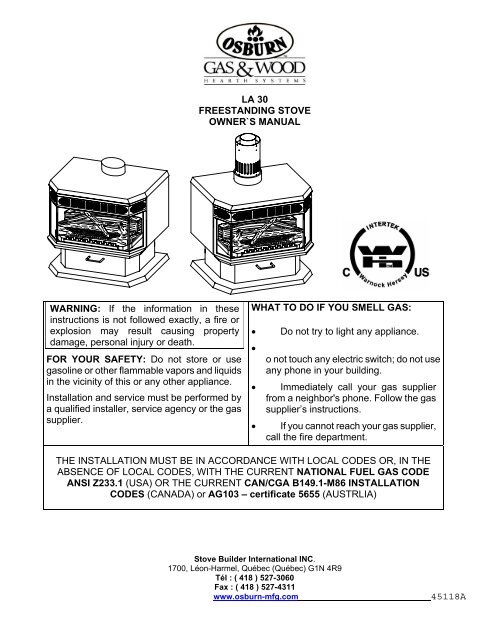
Figure 1INSTALLATION CODESInstallation must conform to local codes. In the absence of local codes, installation must conform tothe current National Fuel <strong>Gas</strong> Code, ANSI Z233.1 (in the U.S.), or with the current installation codeCAN/CGA B149.1-M86 (in Canada). Certified for use in Canada, USA, and Australia. AG103 -Certificate 5655. The conversion shall be carried out in accordance with the requirements of theprovincial authorities having jurisdiction and in accordance with the requirements of the CAN/CGAB149.1-M86 Installation Code. In Australia, the Australian <strong>Gas</strong> Association installation code for gasburning heaters and equipment must be used (refer to AG601 gas installation code for Australia) .The appliance, when installed, must be electrically grounded in accordance with local codes or, in theabsence of local codes, with the National Electric code ANSI/NFPA No. 70 (in the U.S.), or with thecurrent CAN/CSA C22.1 Canadian Electrical code (in Canada), or in other countries with theappropriate national code./2
1.2 FeaturesIGNITION SYSTEM:Standing pilot ignition system with thermocouple flame detection and piezo igniter.GAS CONTROL:<strong>Gas</strong> control valve type:Automatic millivolt powered combination gas control valve with variable flame control forconvenience and on/off switch. Optional wall thermostat, and/or optional remote control areavailable. The gas valve does not require electricity.SAFETY CONTROLS:A safety switch will shut the gas system down in the event of loss of pilot flame.1.3 Intended UseThis appliance is intended to be used as a free-standing room heater when installed according tothese instructions. This appliance is suitable for installation in bedrooms, see section 3.3.1, where themaximum input is within 50 cubic feet of room volume per 1000 BTU/hr, (i.e.1500 minimum cubicfeet). The appliance is also suitable for retrofit into mobile homes as in section 3.4. Installation mustconform with the Standard for Manufactured Home Installations, ANSI A225.1/NFPA 501A.1.4 General SafetyThe appliance must be properly connected to a venting system in accordance with local codes. Thisunit must not be connected to a chimney or flue serving any other appliance.WARNING: Operation of this heater when not connected to a properly installed and maintainedventing system, or any tampering with the safety shut off system may result in carbonmonoxide poisoning and possible death.WARNING: Do not operate this appliance with the glass door or the glass panel(s) removed,cracked, or broken. Replacement of the glass panel(s) should be done by a licensed orqualified person.Installation and repair should be done by a qualified service person. The appliance should beinspected before use and at least annually by a professional service technician. Provide adequateclearances around air openings and allow accessibility clearance for servicing and proper operation.Do not use this heater if any part has been under water. Immediately call a qualified servicetechnician to inspect the heater and replace any part of the control system and any gas control whichhas been under water./3
2.0 OPERATION2.1 Operation SafetyAlways keep the appliance area clear and free from combustible materials, gasoline and otherflammable vapours and liquids. Never obstruct the flow of ventilation air. Keep the front of theappliance clear of all obstacles and foreign materials. Never obstruct or modify the air inlet/outletgrilles of the stove in any manner.CAUTION:Children and adults should be alerted to the hazards of high surface temperature andshould stay away to avoid burns or contact with hot surfaces. Young children should becarefully supervised when they are in the same room as the heater. Clothing or otherflammable material should not be placed on or near the unit.The glass door and grille assembly must be properly installed prior to operation. Never operate theunit with the glass door off or broken since this may cause dangerous indoor air pollution. This unit isnot for use with solid fuel. Do not substitute any parts or materials. Do not abuse the glass door.Behind the control panel door on the front of the pedestal is the control panel shown in Figure 2below.Figure 2/4
2.2 Lighting InstructionsWARNING: If you do not follow these instructions exactly, a fire or explosion may resultcausing property damage, personal injury or loss of life.FOR YOUR SAFETY, READ BEFORE LIGHTINGA. This appliance is provided with a standing pilot flame. When lighting the pilot, follow theseinstructions exactly:B. BEFORE LIGHTING smell all around the appliance area for gas. Be sure to smell next tothe floor because some gas is heavier than air and will settle on the floor.WHAT TO DO IF YOU SMELL GAS- Do not try to light any appliance.- Do not touch any electrical switch: do not use any phone in your building.- Immediately call your gas supplier from a neighbour's phone. Follow the gas suppliersinstructions.- If you cannot reach your gas supplier, call the fire department.C. Use only your hand to push in or turn the gas control knob. Never use tools. If the knobwill not push in or turn by hand, do not try to force or repair it, call a qualified service technician.Forcing or attempted repair may result in a fire or explosion.D. Do not use this appliance if any part has been under water. Immediately call a qualifiedservice technician to inspect the appliance and to replace any part of the control system and anygas control which has been under water.LIGHTING PROCEDURE1. "STOP!" Read the safety information in the previous section.2. Set the thermostat to the lowest setting.3. Turn off all electrical power to the appliance.4. Open the control panel door, hinged to open downward, by pulling the handle toward you.5. Push in the gas control knob slightly and turn clockwise to the "OFF" position. The valve withthe control panel removed is shown in Figure 3.6. Wait a minimum of five minutes to clear out any residual gas. If you then smell gas, STOP!Follow "B" in the Lighting Instruction section. If you don't smell gas, go to the next step./5
Figure 37. Press in the gas control knob and turn counter clockwise to the "PILOT" position.8. Push in the control knob all the way and hold it in. Immediately push the piezo ignition button (thebutton to the right) repeatedly so that it clicks; continue until the pilot ignites. Maintain pressureon the control knob for about one minute after ignition. Then release the control knob; if the pilotflame goes out repeat step 8; if the pilot flame remains on then turn the valve knob counterclockwise to the "ON" position.NOTE: If the pilot lights, but will not stay on after several tries, turn the gas control knob to the"OFF" position and call your service technician or gas supplier. If the control knob does notpop out when released, STOP - shut off the gas supply to the control valve, andIMMEDIATELY call your service technician or gas supplier.9. Close the access door grille by lifting it and allow the springs to pull it closed.10. Turn the burner switch to on (see Figure 2).11. If equipped with a wall switch, select the "ON" position. If equipped with a thermostat orauxiliary control, set it to the desired setting.SHUTDOWN PROCEDURE1. To turn off the main burner only, turn off the wall switch, thermostat, or On/Off switchlocated on the control panel shown in Figure 2 located behind the control panel door on the frontof the pedestal.2. For complete shutdown of the appliance, depress the gas control knob and turn it clockwiseto the "OFF" position.2.3 Heat Output AdjustmentThe appliance valve has a HI/LO knob to select the heat output and flame height (see Figure 2).Natural gas units can be turned down by 30%, propane units can be turned down by 25%./6
3.1 Installation & Safety Notes3.0 INSTALLATIONRead all instructions before beginning and follow them carefully during installation to ensure maximumbenefit and safety. Failure to follow these instructions will void your warranty and may present a firehazard. See the <strong>Osburn</strong> warranty at the back of this manual for improper installation disclaimers. Thisstove and its components are certified and safe when installed in accordance with this manual.WARNING:Do not connect 120 VAC to the gas control valve or its wiring, as this will damagethe valve.3.2 UnpackingPlease check the appliance carefully for any damaged or missing components (specifically check theglass condition). Report any problems to your dealer.The stove is shipped with the logs and burner packaged inside the firebox. See section 4.5, removethe door, cut the log tie, remove it and the log protector. All other standard parts are already in place.3.3 InstallationIn planning the installation, it is necessary to install certain items before the unit is completelypositioned and installed. These include the vent system, the gas piping and the optional fan.NOTE: All installations require venting.3.3.1 Bedroom InstallationThis appliance is suitable for installation in bedrooms where the maximum input is within 50 cubic feetof room volume per 1000 BTU/hr, (i.e.1500 minimum cubic feet). Where applicable, the installationmust conform to the CR89-001 standard. A listed thermostat must be installed with a wire gauge andlength conforming to Table 2 on page 14.3.3.2 Minimum Clearances To Combustible ConstructionA. Sidewall: 7.5" (190 mm) measured to unitB. Back wall: 1.5" (38 mm) measured to unitC. Ceiling: 37" (940 mm) measured to cooktopD. Floor: Install directly on combustible floorE. Corner 1.5" (38 mm) measured to unitF. Front wall: 48" (1219 mm) measured to glassG. Alcove: (Depth) 48" (1219 mm)(Width) 38" (965 mm)H. Vent Cap: (Above) 14" (355 mm)Horizontal (Side) 6" (150 mm) clearance to combustibles(Side) 2" (50 mm) clearance to non-combustibles/7
MINIMUM ENCLOSURES ARE AS FOLLOWS:CAUTION:Due to high temperatures, the appliance should be located out of traffic and away fromfurniture and draperies. Provide a minimum 48" (1219 mm) front clearance to the unit.Note: The appliance may be installed directly on combustible flooring providing the unit stability ismaintained. Although the back wall and corner clearance is 1.5" (38mm), we recommend 6"(150mm) for fan installation and removal.3.3.3 Chimney Vent Installation3.3.3.1 Direct ventThe stove must be connected to Simpson model DV-GS vent, Security Chimneys International(Secure Vent) or Selkirk (Direct-Temp) only. Only install the vent components according to themanufacturer's instructions. Use a maximum of two 90 elbows or four 45 elbows. Slopehorizontal pipe at least 1/4" (6 mm) rise per foot of horizontal run. Allow 2" (50 mm) clearance tothe vent. A vinyl siding standoff must be used when terminating horizontally to vinyl siding. Referto the graph for allowable vent configurations.Note: If at any time the vent-air intake piping is dismantled, use the vent manufacturersinstructions and the sealing instructions on page 11 for reassembly./8
THE MINIMUM VENT SYSTEM FOR HORIZONTAL TERMINATION MUST CONSIST OF24'' (610 mm) vertical length directly on top of stove90 elbow12" (305 mm) length horizontally (or 9" (230 mm) telescoping)round support box/wall thimblehorizontal termination cap 0984termination cap heat shield 0984HS (North America only)THE MAXIMUM HORIZONTAL VENT SYSTEM CONSISTS OF:6' (1830 mm) vertical length directly on top of the stove90 elbow10' (3050 mm) maximum horizontal lengthhorizontal termination cap 0984snorkel kits can be used if needed. (Part #981 - 36" (915 mm) or Part #982 - 14" (355 mm))(North America only)vent terminal heat shield 0984HS (North America only)Do not exceed more than 10' (3050 mm) of horizontal length of vent.THE MAXIMUM VERTICAL SYSTEM CONSISTS OF:up to 30' (9145 mm) of vertical lengthfire stopflashingcollarlow profile termination cap 0980Use a ceiling fire stop when penetrating a ceiling. Use a round support box/wall thimble whenpenetrating an inside wall, or on an outside wall, only when additional support or decorative trim isrequired. The round support box is not required on basic installations.NOTE: In Canada local codes may require the use of a wall thimble on horizontal terminations. Usepart # 942./9
TYPICAL CHIMNEY INSTALLATION:Figure 5MINIMUM VENT REQUIREMENT:Figure 6/10
USE OF SEALANTSealant is required on vent system joints. On longer vent runs, especially vertical runs, sealant willensure that the combustion air enters from outdoors, and not through the vent joints. Use Mil-PacBlack sealant (or equivalent), available from local suppliers or <strong>Osburn</strong> dealers, on the inner pipe joint,applying the sealant around the outside of the male part of the vent. A bead of silicone should beused on the outside of the joint after assembly to seal the supply air./11
VENT TERMINAL LOCATIONSFigure 7VAVent TerminationAir Supply InletA = clearances above grade, veranda, porch, deck, or balcony [* 12" (305 mm) minimum]B = clearance to window or door that may be opened [* 12" (305 mm) minimum]C = clearance to permanently closed window [minimum 12" (305 mm) recommended to preventcondensation on window]D = vertical clearance to ventilated soffit located above the terminal within a horizontal distance of24" (610 mm) from the center-line of the terminal [18" (455 mm) minimum]E = clearance to unventilated soffit [18" (455 mm) minimum]F = clearance to outside corner = 10" (255mm)G = clearance to inside corner = 2" (50mm) to non-combustibles, or 6" (150mm) to combustiblesH = 36" clearance to each side of the centreline extended above the meter / regulator assemblyto a maximum vertical distance of 15ft (4.57M)I = 36" clearance to service regulator vent outletJ = clearance to non-mechanical air supply inlet to building or the combustion air inlet to anyother appliance [* 12" (305 mm) minimum]K = clearance to a mechanical air supply inlet [* 72" (1829 mm) minimum]L = clearance above paved side-walk or a paved driveway located on public property [* 84"(2134 mm) minimum]M = clearance under veranda, porch, deck, or balcony [* 12" (305 mm) minimum ] a vent shall not terminate directly above a side-walk or paved driveway which is locatedbetween two single family dwellings and serves both dwellings* only permitted if veranda, porch, deck, or balcony is fully open on a minimum of 2 sidesbeneath the floor** as specified in CGA B149 Installation Code (1991) NOTE: local codes or regulations mayspecify different clearances* follow ANSI Z223.1 for U.S.A.NOTE: Refer to AG601 gas installation code for Australia./12
3.3.3.2 Optional B-Vent InstallationThis unit may be modified for use as a vented room heater, by using the optional <strong>LA30</strong> B-Ventadapter. Follow instructions included with the adaptor when using this option.3.3.4 <strong>Gas</strong> Line InstallationA qualified gas fitter should install the gas line in accordance with all local building codes using apiping system meeting CAN/CGA 6.10, AGA 3, ANSI Z21.24 or Z21.45.A plugged tapping is provided on the gas control for a test gauge connection to measure themanifold pressure, as well as a connection for inlet pressure measurement.This appliance must be isolated from the gas supply piping system by closing its individual manualshut off valve during any pressure testing of the gas supply piping system at test pressures equal toor less than psig (3.45 kPa).The appliance and its individual shut off valve must be disconnected from the gas supply pipingsystem during any pressure testing of the system at test pressures in excess of psig (3.45 kPa).WARNING: Do not use an open flame to test for gas leaks.Figure 10aFigure 10bThe gas line can be installed from two locations:1. Install the gas line behind the stove and connect it to the inlet valve piping in the pedestal rearsee Figure 10a.2. Install the gas line from below the pedestal base through the 2"x 2" hole as shown in Figure10b./13
3.3.5 Thermostat, Wall Switch, Or Remote Control InstallationThe burner control switch is located on the control panel behind the front door of the pedestal (seeFigure 2). For your convenience, the stove can also be operated by a thermostat, a wall switch or aremote control. Millivolt thermostats and remote control kits are available from any authorized<strong>Osburn</strong> dealer.NOTE: The thermostat or wall switch MUST be rated for millivolt use. Minimize splicing in allmillivolt wiring & solder all unavoidable splices.REMOTE CONTROL INSTALLATIONPlease refer to instructions included with kit.THERMOSTAT OR WALL SWITCH INSTALLATION1. Mount the thermostat or wall switch in the desired location and run "two conductor thermostatwire" to the burner control switch (Figure 11a). To bypass the burner control switch, run thewires directly to the gas valve (Figure 11b).Purchase "two conductor thermostat wire", which is not provided, at any local supplier. Thegauge of thermostat wire will determine the maximum wire length and distance at which tolocate the thermostat or wall switch. See table 2 below and the information packaged with thethermostat. Be aware that, as the length of wire increases, the probability of adequate operatingvoltage decreases.TABLE 2THERMOSTAT WIRE INFORMATIONWIRE SIZEMAX. WIRE LENGTHAWG mm ft. m22 0.6 10 3.120 0.8 25 7.618 1.0 40 12.216 1.3 64 19.514 1.6 100 30.52. Solder an appropriate wire connector to each wire. To connect to the burner switch, 1/4" femalequick connects are required and to connect directly to the valve use spade tongue connectors.3. Check tests can be performed on the valve by referring to the trouble shooting guide./14
Figure 11aFigure 11b/15
Figure 133.3.6 Firebox Component InstallationAll components necessary for operation are in the firebox. The log set is in place on the burner and isprotected with styrofoam. Remove the door and the foam. Otherwise, no pre-firing assembly isrequired.3.3.6.1 Optional Ember InstallationNOTES: Optional embers are for North American units only. Use of embers must be done inaccordance with the following instructions:1. Remove ember bag from firebox.2. Install embers as shown in Figure 14.NOTES: Embers must not cover burner ports.Spacing between all embers is to be a minimum of 1/2".Figure 14/16
3.3.7 Initial FiringNOTE: Make sure the pressure relief plate is in place before firing the appliance.When lit for the first few times, the appliance may emit an odour resulting from evaporation of paintand lubricants used in the manufacturing process. Open a door or window for ventilation. Anyonewith a respiratory condition may need to leave the room during the initial firings.Occasionally, after a cold start, vapour may condense and fog the glass, and the flames may bepartially blue. After a few minutes the moisture will disappear and after several more minutes theflames should become yellow.NOTE: It may take up to 25 minutes for the flames to reach maximum height.3.3.7.1 Manifold Pressure Regulator AdjustmentThe manifold pressure regulator controls gas input and flame height, and is preadjusted at the factory.No further adjustment is required. Manifold pressure can be verified only.3.3.7.2 Pilot Flame AdjustmentFor proper operation, the pilot and main burner flames must be steady and not lifting off or floating.The top 3/8" (10-13 mm) of the thermopile should be engulfed by the pilot flame. The pilot flameadjustment should be performed by a qualified service person only. To adjust the pilot flame, turn thepilot adjustment screw counterclockwise to increase, and clockwise to decrease the flame. Ensurethat the pilot flame completely engulfs the thermopile, as shown in Figure 15.Figure 153.3.7.3 Altitude AdjustmentAll valves have been preset and certified for installation at elevations from 0 - 4500 feet (0-1372 m)above sea level./17
When installing this stove at higher elevations, it is necessary to decrease the input rating by changingthe existing burner orifice to a smaller size. Input should be reduced 4% for each additional 1000 feetabove sea level.Use Tables 3A & 3B or check with the local gas authorities for proper orifice size identification. Forthe USA, derate the heater from sea level according to the gas installation code.TABLE 3AALTITUDE ADJUSTMENT BY CHANGINGORIFICE (NATURAL GAS ONLY)ALTITUDEup to (ft)REDUCTION(%)ORIFICE SIZE TARGET INPUT MANIFOLDPRESSURE (in. wc)4500 - 37 30,000 3.55500 4 38 28,8006500 8 39 27,6007500 12 40 26,4008500 16 40 25,2009500 20 41 24,00010500 24 42 22,80011500 28 43 21,600TABLE 3BALTITUDE ADJUSTMENT BY CHANGINGORIFICE (PROPANE/LP GAS ONLY)ALTITUDEup to (ft)REDUCTION(%)ORIFICE SIZE TARGET INPUT MANIFOLDPRESSURE (in. wc)4500 - 53 30,000 10.05500 4 54 28,8006500 8 54 27,6007500 12 54 26,4008500 16 55 25,2009500 20 55 24,00010500 24 55 22,80011500 28 56 21,600/18
3.4 Manifactured (mobile) Home InstallationThis heater may be installed in manufactured (mobile) homes after the first sale. See and comply withthe Installation Codes noted on page 2. This Direct Vent System Appliance must be installed inaccordance with these instructions and the Manufactured Home Construction and Safety StandardTitle 24 CFR, Part 3280, or the current Standard for Fire Safety Criteria for Manufactured HomeInstallations, Sites, and Communities ANSI/NFPA 501A, and with CAN/CSA Z240 MH Mobile HomeStandard in Canada.NOTE: Refer to AG601 gas installation code for Australia.1. Venting must be installed in the building interior or in an enclosed chase.2. Use a maximum of two offsets, for example: four 45 elbows, or two 90 elbows. Slope horizontalpipe at least 1/4" (6.4mm) rise per foot of run. Horizontal runs should not exceed the vertical rise.3. The vent shall extend at least 3 ft. (914mm) above the point where it passes through the roof andat least 2 ft. (610mm) above any wall, roof, or adjacent building within 10 ft. (3.1 meters) of it.4. Do not fill the 2" (50mm) air space around the vent with insulation or any other material.Insulation placed in this area could cause adjacent combustibles to overheat.5. Do not compromise the structural integrity of the manufactured home wall, floor, or ceiling.6. The appliance must be grounded to the steel chassis of the home with 8 ga. copper wire using aserrated or star washer to penetrate paint or protective coating and ensure grounding. Secure thewire to the .182" dia. hole in the center rear of the pedestal base, see Figure 16.7. Secure the heater to the floor with the use of two carriage bolts. Locate the heater in the desiredposition and turn the carriage bolts through the two 3/8" holes in the rear of the pedestal base asshown in Figure 16.8. See section 3.3.3 Chimney Vent Installation for the required vent components and configurations.Figure 16/19
3.5 Field ConversionsService and repair should be done by a qualified service person. Local building codes andinstallation codes listed in this instruction manual must be adhered to.Follow the instructions included in the conversion kit.4.1 Maintenance Safety4.0 MAINTENANCETurn off the gas to the main burner and allow the heater to cool for up to 30 minutes beforeservicing. Service and repair should be done by a qualified service person. The appliance should beinspected before use and at least annually by a qualified service person. More frequent cleaning maybe required due to excessive lint from carpeting, bedding material, etc. It is important that the accessdoor compartment, burner, and circulating air passage-ways be kept clean to provide for adequatecombustion and ventilation air flow. Do not substitute materials or use components other than factorysupplied.CAUTION: Label all wires prior to disconnection when servicing controls. Wiring errors can causeimproper and dangerous operation.4.2 Recommended Service1. Examine the venting system periodically.2. Visually check the burner and pilot flame periodically. If the burner is dirty, see section 4.5,remove it, and vacuum and/or clean it with a damp cloth. Visually check height and colour offlame.3. Clean the glass as needed. See section 4.3 for instructions on glass cleaning.4. Have the appliance inspected annually by a professional service technician.5. Clean the appliance periodically.4.3 Glass CleaningThe inside of the glass may require periodic cleaning to remove deposits left from impurities in the gasand combustion air. For best results, use a ceramic glass cleaner or polish. Avoid the use ofammonia based cleaners such as Windex. A suitable cleaner is available from your dealer. Do notclean while hot. Do not use abrasive cleaners.4.4 Burner & Pilot Cleaning1. Refer to section 4.5, remove the burner and check to make sure that the burner orifice is clean.2. Visually inspect the pilot. Brush or blow away any dust, lint or foreign debris. If the pilot orifice isplugged, disassembly may be required to remove any foreign material from the orifice or tubing.When the appliance is back in service, check the burner flame pattern with the Pilot FlameFigures in section 3.3.7.2. For relighting, refer to the lighting instructions in section 2.2./20
4.5 Firebox Disassembly & reassemblyThe following procedure is to be performed by qualified service personnel ONLY.Turn off the gas supply and allow the heater to cool before proceeding.REMOVE THE VALVE AS FOLLOWS:1. Open the side doors, and remove the top louvre by sliding it forward out of the clips under the topas in Figure 17.Figure 172. Hold the glass door while opening the four draw latches at the sides of the heater, then remove.Proper log placement is very important. The one piece log set is designed to be placed in oneposition only.3. Lift the log set off the location pins on the burner tray as shown in Figure 18, and remove.4. Disconnect the gas line at the union upstream of the valve.5. Remove the coal grate by lifting it up and out, and remove the burner tray assembly as a unit bypulling it forward and then lifting it up and out as shown in Figure 17.6. Remove the 14 - 5/16" hex head screws holding the firebox bottom plate.figure 18/21
7. To remove the control panel, open the door and remove the four side screws.8. Remove the blue wires connected to the valve, the wire connected to the sparker, and the twovalve extension knobs.9. Lift the firebox bottom plate and valve assembly up and out of the firebox.10. Reassemble the components in reverse order.4.6 FanAn optional fan is available. Installation and operational instructions are included in the fan kit.5.0 AUSTRALIAN DRESS GUARDFigure 19THE GUARD IS FITTED TO THIS APPLIANCE TO REDUCE THE RISK OF FIRE OR INJURY FROMBURNS AND NO PART OF IT SHOULD BE PERMANTLY REMOVED.FOR PROTECTION OF YOUNG CHILDREN OR THE INFIRM, A SECOND GUARD IS REQUIREDNOTE: The following information is attached to the Australian Dress Guard./22
6.0 TROUBLE SHOOTINGSYMPTOM POSSIBLE CAUSE CORRECTIVE ACTIONI. Pilot will not light afterrepeated triggering of thepiezo ignition buttonA. No spark at electrode (weak or no heat source for pilot ignition)1. Poor connections at starter 1. Reconnect if looseand ignition electrode2. Broken ceramic cover on 2. Replace pilot assemblyignition electrode3. Defective piezo igniter 3. Replace piezo igniter4. Poor grounding of piezo 4. Tighten mounting nut and/or igniterigniterscrewsB. No gas or low gas pressureII. Pilot will not stay lit afterfollowing the lightinginstructions1. <strong>Gas</strong> line shut off(s) may notbe turned on2. No gas supply (LPG)3. Air in gas lines4. <strong>Gas</strong> lines may not beconnected5. Low pressure may becaused by bent line6. Valve control knob not fullydepressed in “PILOT”positionWeak or improperly locatedpilot flameDefective thermocoupleThermocouple not installedproperlyOpen wire connection inpilot circuitDefective Valve1. Turn on shut-off valves2. Check propane tank; you may beout of fuel3. Purge gas lines4. Connect all gas lines5. Check for a kinked line6. Fully depress control knobA. Thermocouple / Valve1. Adjust and clean pilot. The flamemust impinge on or engulf thethermocouple, as shown in Figure222. Replace thermocouple3. Make sure all wire connections atthe gas valve terminals are tightand the thermocouple is fullyinserted into the mounting bracket4. Check wire continuity andconnections in the pilot circuit5. Connect the millivolt meter probesto the thermopile terminals on thegas valve. Turn the valve to the“PILOT” position, depress, andlight. If the meter reading is greaterthan 250 millivolts after 30seconds, the thermopile is good. Ifthe pilot does not stay lit, the valveis defective./23