Schubert & Salzer 8021 Sliding Gate Control Valve - RM Headlee
Schubert & Salzer 8021 Sliding Gate Control Valve - RM Headlee
Schubert & Salzer 8021 Sliding Gate Control Valve - RM Headlee
- No tags were found...

You also want an ePaper? Increase the reach of your titles
YUMPU automatically turns print PDFs into web optimized ePapers that Google loves.
Earth Syst. Dynam. Discuss., 3, C288–C295, 2012www.earth-syst-dynam-discuss.net/3/C288/2012/© Author(s) 2012. This work is distributed underthe Creative Commons Attribute 3.0 License.Earth SystemDynamicsDiscussionsInteractive comment on “The influence ofvegetation dynamics on anthropogenic climatechange” by U. Port et al.U. Port et al.ulrike.port@zmaw.deReceived and published: 16 August 2012Dear reviewer,thank you very much for reading our manuscript so carefully and for your comments.Referee: The authors designed four simulation experiment (as listed in Table 2) toinvestigate the effect of vegetation dynamic on global climate. It looks to me that theindividual and combined climate influence from biogeochemical and biogeophysicaleffects can be represented by analyzing the following results:DYN - STAT (Eq. 1) the combined biogeochemical and biogeophysical effects onclimate;DYN - STAT_PS (Eq. 2) the biogeophysical effects on climate;C288STAT_PS - STAT (Eq. 3) the biogeochemical effects on climate.The authors analyzed in detail the results of (2), but not (1) and (3).Author: The structure of this paper is chosen in the way that the net effect isanalysed by separating in the biogeophysical and the biogeochemical effect. Inorder to assess the biogeophysical effect, the energy balance is analysed on aregional scale. The biogeochemical effect acts globally. That is why we limit theanalysis of the biogeochemcial effect on the global climate and the carbon cycle.Referee: Also, it would be quite interesting to investigate the linearity of climateresponse from biogeochemical and biogeophysical effects, i.e., to compare the climateresponse between (1) and the sum of (2) and (3).Author: The overview of the simulations and their objectives (Equations (1)to (3)) are correct. However, analysing the sum of (2) and (3) and compare it with(1) does not make sense to us since the sum of (2) and (3) and (1) are equivalent:Net effect = BGP (2) + BGC (3) = DYN - STAT_PS + STAT_PS - STAT = DYN - STAT(1).Referee: Related to: “We assume anthropogenic CO2 emissions according to theRCP 8.5 scenario in the period from 1850 to 2120 and shut them down afterwards toevaluate the equilibrium response of the Earth System by 2300“.I believe the response of the Earth climate system, including the response of the deepocean and dynamic vegetation, would not reach equilibrium by 2300. For example, itwill take thousands of years for the response of the full ocean to reach equilibrium.Author: Right, the term ’equilibrium response’ is inappropriate in this context.We will change it to ’stabilising’.Referee: RCP scenario is for atmospheric CO2 concentrations. How was transientCO2 emission, as used in simulations, derived from the RCP 8.5 concentrationC289
<strong>Control</strong> <strong>Valve</strong> <strong>8021</strong>-GS3with integrated p/p and i/p - positioner, Type 8047Disc pair: carbon - stainless steel, coatedActuator SizeSpring Range (psi)Supply Pressure (psi)For temperatures exceeding 250°F:consider operation limitsDN <strong>Control</strong> On-Off <strong>Control</strong> On-Off <strong>Control</strong> On-Off <strong>Control</strong> On-Off <strong>Control</strong> On-Off <strong>Control</strong> On-Off1/2" 1450 1450 1450 1450 1450 1450 1450 1450 - - - -3/4" 1117 1117 1392 1392 1450 1450 1450 1450 - - - -1" 827 827 1030 1030 1421 1421 1450 1450 1450 1450 1450 14501 1/4" 609 609 754 841 1059 1059 1276 1276 1450 1450 1450 14501 1/2" 421 421 522 638 711 711 870 870 1450 1450 1450 14502" 247 276 305 421 421 421 508 580 870 870 1044 10442 1/2" 203 232 247 348 348 348 421 493 711 711 856 8563" 116 145 145 218 203 203 247 319 421 421 508 6384" 73 87 87 145 131 131 145 203 261 261 319 4065" 44 58 58 87 87 87 102 131 174 174 203 2766" 29 44 44 73 58 58 73 102 131 131 145 2038" 22 26 26 38 36 36 44 58 73 73 87 11610" 13 16 16 26 22 22 28 36 46 46 55 75Spring Configuration5820 in² 40 in²22 to 44 26 to 55 17 to 32 22 to 3973maximum pressure psi3 (Standard) 44458maximum pressure psi80 in²17 to 32 22 to 3944 65maximum pressure psi3 (Standard) 4 6 (Standard)8StandardPressure limits DIN and ANSIPN16 PN40 PN100 ANSI 150 ANSI 300 ANSI 600P max. 235 580 1450 235 580 1160Disc pair: STN 2Actuator SizeSpring Range (psi)Supply Pressure (psi)DN <strong>Control</strong> On-Off <strong>Control</strong> On-Off <strong>Control</strong> On-Off <strong>Control</strong> On-Off <strong>Control</strong> On-Off <strong>Control</strong> On-Off1/2" 798 798 986 1015 1378 1378 1450 1450 1450 1450 1450 14503/4" 537 537 667 769 928 928 1131 1131 1450 1450 1450 14501" 363 377 450 580 624 624 769 798 1291 1291 1450 14501 1/4" 247 276 319 435 435 435 522 580 899 899 1088 11601 1/2" 160 189 203 290 276 276 348 392 580 580 696 8412" 87 116 116 174 160 160 189 247 334 334 392 5082 1/2" 73 87 87 145 131 131 160 203 261 261 319 4063" 44 58 51 87 73 73 87 116 160 160 189 2474" 22 29 29 44 44 44 58 73 87 87 116 1455" - - 22 29 29 29 36 51 58 58 73 1026" - - 15 22 22 22 26 36 44 44 51 738" - - - - - - - - - - - -Spring Configuration20 in² 40 in²22 to 44 26 to 55 17 to 32 22 to 3958 73 4458maximum pressure psi3 (Standard) 4maximum pressure psi80 in²17 to 32 22 to 3944 65maximum pressure psi3 (Standard) 4 6 (Standard)8StandardPressure limits DIN and ANSIPN16 PN40 PN100 ANSI 150 ANSI 300 ANSI 600P max. 235 580 1450 235 580 1160
<strong>Control</strong> <strong>Valve</strong> <strong>8021</strong>-GS3with integrated digital positioner, Type 8049(also on-off valves and valves with other side-mounted positioner)Disc pair: carbon - stainless steel, coatedActuator SizeFor temperatures exceeding 250°F:consider operation limitsSupply Pressure (psi) 65 80 44 58 44 65DN20 in² 40 in² 80 in²maximum pressure psi maximum pressure psi maximum pressure psi1/2" 1450 1450 1450 1450 - -3/4" 1450 1450 1450 1450 - -1" 1450 1450 1450 1450 - -1 1/4" 1276 1450 1450 1450 - -1 1/2" 972 1204 1450 1450 - -2" 638 783 1088 1320 1450 14502 1/2" 537 653 914 1102 1160 11603" 334 421 580 696 696 6964" 218 232 363 450 479 4795" 145 160 247 305 334 3346" 102 116 189 218 232 2328" 51 65 102 131 218 23210" 39 49 67 81 138 152Spring Configuration 3 (Standard) 4 3 (Standard) 4 6 (Standard) 8StandardPressure limits DIN and ANSIPN16 PN40 PN100 ANSI 150 ANSI 300 ANSI 600P max. 235 580 1450 235 580 1160Disc pair: STN 2Actuator Size20 in² 40 in² 80 in²Supply Pressure (psi) 65 80 44 58 44 65DN1/2" 1450 1450 1450 1450 - -3/4" 1175 1450 1450 1450 - -1" 870 1088 1450 1450 1450 14501 1/4" 653 812 1117 1349 1450 14501 1/2" 450 551 769 928 1044 10442" 261 319 450 551 928 11172 1/2" 218 261 377 450 769 8993" 131 145 218 276 464 5224" 65 87 131 160 276 3345" 44 51 87 94 189 2326" 29 36 58 65 131 1608" - - - - - -Spring Configuration 3 (Standard) 4 3 (Standard) 4 6 (Standard) 8Standardmaximum pressure psi maximum pressure psi maximum pressure psiPressure limits DIN and ANSIPN16 PN40 PN100 ANSI 150 ANSI 300 ANSI 600P max. 235 580 1450 235 580 1160
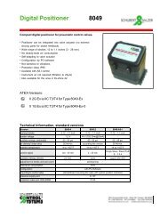
<strong>Control</strong> <strong>Valve</strong> <strong>8021</strong>-GS3with integrated positionerOrdering Number System1 2 3 4 5 6 7 8 9 10 11 12 13 14 15 168 0 2 1 / V G M Z S 1 - 5 : Please quote all 5 sections.6 - 12: Quote only if required.Symbol: "V": <strong>Valve</strong>TypeSize"R": Repair kit (sealings)1. <strong>Valve</strong> type 2. Body design 3. Body 4. Safety 5. Actuator 6. Special 7. Springs 8. Stem sealingmaterial function versionG GS-<strong>Control</strong> E GS3 - flangeless 0 carbon steel 0 spring closes 6 diaphragm M to state if some - standard - PTFE-packing<strong>Valve</strong> w ith design acc. ASTM A572 actuator 20 in² sections 7-16 self-adjustingpneumatic ANSI 150 ASTM A216 (NPT) are quoted 4 8 springs (Standard)actuator F GS3 - flangeless 1 spring opens 7 diaphragm(type <strong>8021</strong>) design acc. 1 stainless steel actuator 40 in² 8 16 springsANSI 300 316 Ti / 318 (NPT) 1 stainlessK GS3 - flangeless 8 diaphragm steel bellowdesign acc. actuator 80 in² 316 Ti (max.ANSI 600 (NPT) press. 480 psi)G GS3 - flangelessdesign acc. DIN,145-580 psiH GS3 - flangelessdesign acc. DIN,1450 psi9. Moving 10. Fixed 11. Cv-Values 12. Flow 13. Accessories 14. Positioners 15. Signalling 16. Further specialdisc disc characteristic equipment versions- carbon - stainless steel/ - 100 % (stand.) - linear Z State, if in - w ithout - w ithout S Other specialStellite A red. to 63 % follow ing 1 p/p positioner versions have9 STN2/STN3 1 STN2 - plate 1 red. to 40 % 1 equal-% sections Type 8047 0 2 limit sw itches to be quoted in(only in comb. B red. to 25 % accessories 3 i/p positioner M12x1 DC letters!w ith the pos."9") 2 red. to 16 % are quoted. Type 8047 10-30V PNPA SIC 3 STN2 - plate C red. to 10 % 6 i/p positioner(only in comb. 3 red. to 6,3 % Type 8047B FUY w ith the pos."9") 4 red. to 2,5 % Eex ib IIC T6 w ith5 red. to 1 % plug connc. M12x16 red. to 20 % 8 i/p positioner w ith7 red. to 12 % plug connc. M12x18 red. to 2% C digital positioner9 red. to 0,4% type 8049, 4-w ireR digital positionertype 8049, 2-w ireT digital positionertype 8049, AS-iversionW digital positionertype 8049, 2-w ireex-versionOrdering Example:<strong>8021</strong>/080VGE106M------Z8GS3-<strong>Control</strong> <strong>Valve</strong> Type <strong>8021</strong> with pneumatic actuator, 3", flangeless design design acc. ANSI 150,stainless steel 316 Ti, spring to close, actuator diaphgram 20 in², standard springs, PTFE-V-shaped sealing,function unit carbon-stainless steel 316 Ti coated, flow characteristic linear, i/p-positioner
<strong>Control</strong> <strong>Valve</strong> <strong>8021</strong>-GS3with integrated positioner580 psi (PN 40)1450 psi (PN 100)ANSI #150ANSI #300ANSI #600Pressure - Temperature ratings for GS3 <strong>Valve</strong>s<strong>Sliding</strong> unit: carbon - stainless steel, coatedmaximum pressures for GS3-valves (psi)DN 210 °F 300 °F 400 °F 480 °F 570 °F 660 °F 210 °F 300 °F 400 °F 480 °F 570 °F 660 °F1/2" - 2 1/2" 580 550 495 465 450 420 580 550 495 465 450 4203" 580 550 495 465 450 420 520 495 480 375 320 2754" 480 450 420 390 365 350 480 450 375 350 290 2455" 335 305 290 275 260 245 320 305 245 230 190 1606" 230 220 205 190 175 175 230 220 190 160 130 1158" (PN16 only) 230 220 205 190 175 160 - - - - - -10" (PN16 only) 150 145 140 120 105 100<strong>Sliding</strong> unit: carbon - stainless steel, coatedmaximum pressures for GS3-valves (psi)<strong>Sliding</strong> unit: STN2maximum pressures for GS3-valves (psi)DN 210 °F 300 °F 400 °F 480 °F 570 °F 660 °F 210 °F 300 °F 400 °F 480 °F 570 °F 660 °F1/2" 1450 1380 1260 1190 1115 1045 1450 1380 1260 1190 1115 10453/4" 1450 1380 1260 1190 1115 1045 1450 1380 1260 1190 1115 10451" 1450 1380 1260 1190 1115 1045 1450 1380 1260 1190 1115 10451 1/4" 1450 1380 1260 1190 1115 1045 1450 1380 1260 1190 1000 8701 1/2" 1450 1380 1260 1190 1115 1045 1045 1000 945 770 625 5352" 1450 1380 1260 1190 1115 1045 1115 1060 1015 810 665 5802 1/2" 1160 1100 1045 970 900 870 900 855 810 655 535 4653" 695 655 625 580 535 520 520 495 480 375 320 275<strong>Sliding</strong> unit: carbon - stainless steel, coatedmaximum pressures for GS3-valves (psi)<strong>Sliding</strong> unit: carbon - stainless steel, coatedmaximum pressures for GS3-valves (psi)<strong>Sliding</strong> unit: carbon - STN2maximum pressures for GS3-valves (psi)DN 210 °F 300 °F 400 °F 480 °F 570 °F 660 °F 210 °F 300 °F 400 °F 480 °F 570 °F 660 °F1/2" - 2 1/2" 580 550 510 480 450 435 580 550 510 465 450 4203" 580 550 510 480 450 435 520 495 480 375 320 2754" 480 450 420 390 365 350 480 450 375 350 290 2455" 335 305 290 275 260 245 320 305 245 230 190 1606" 230 220 205 190 175 175 230 220 190 160 130 115<strong>Sliding</strong> unit: carbon - stainless steel, coatedmaximum pressures for GS3-valves (psi)<strong>Sliding</strong> unit: carbon - STN2maximum pressures for GS3-valves (psi)DN 210 °F 300 °F 400 °F 480 °F 570 °F 660 °F 210 °F 300 °F 400 °F 480 °F 570 °F 660 °F1/2" - 5" 230 220 190 175 145 115 230 220 190 175 145 1156" 230 220 190 175 145 115 230 220 190 160 140 1158" 230 220 190 175 145 115 - - - - - -10" 150 145 140 120 105 100<strong>Sliding</strong> unit: carbon - STN2maximum pressures for GS3-valves (psi)<strong>Sliding</strong> unit: STN2maximum pressures for GS3-valves (psi)DN 210 °F 300 °F 400 °F 480 °F 570 °F 660 °F 210 °F 300 °F 400 °F 480 °F 570 °F 660 °F1/2" - 1 1/4" 1160 1115 1030 955 915 870 1160 1115 1030 955 915 8701 1/2" 1160 1115 1030 955 915 870 1045 1000 945 770 625 5352" 1160 1115 1030 955 915 870 1115 1060 1015 810 665 5802 1/2" 1160 1100 1030 955 900 870 900 855 810 655 535 4653" 695 655 625 580 535 520 520 495 480 375 320 275
<strong>Control</strong> <strong>Valve</strong> <strong>8021</strong>-GS3with integrated p/p and i/p - positioner, Type 8047Dimensions and WeightsDDLi/p - positionerType 8047Lp/p - positionerType 8047Size Ø A C1* C2* Ø DL StrokeWeight (lb.)for actuatorfor actuator20 in² 40 in² 80 in² 20 in² 40 in² 80 in²1/2" 2.52 16.93 15.75 6.5 8.74 8.74 2.2 0.24 16.5 21.3 29.53/4" 2.83 17.13 15.94 6.5 8.74 8.74 2.2 0.24 17 21.8 301" 3.23 17.32 16.14 6.5 8.74 8.74 2.2 0.24 17.9 22.7 30.91 1/4" 3.5 17.52 16.34 6.5 8.74 8.74 2.2 0.24 18.7 23.5 31.71 1/2" 3.9 17.72 16.54 6.5 8.74 8.74 2.2 0.24 19.6 24.5 32.62" 4.57 18.11 16.93 6.5 8.74 8.74 2.52 0.31 23.1 28 36.12 1/2" 5.43 18.5 17.32 6.5 8.74 8.74 2.68 0.31 27.1 32 40.13" 6.02 18.9 17.72 6.5 8.74 8.74 2.76 0.31 29.6 34.4 42.54" 7.24 19.29 18.11 6.5 8.74 8.74 2.95 0.33 37.1 42 50.15" 8.35 19.88 18.7 6.5 8.74 8.74 3.15 0.33 46.5 51.3 59.56" 9.53 20.47 19.29 6.5 8.74 8.74 3.15 0.33 54.6 59.4 67.68" 11.89 21.65 20.47 6.5 8.74 8.74 3.66 0.33 1.64 1.73 1.8710" 14.17 22.64 21.46 6.5 8.74 8.74 3.78 0.35 1.85 1.96 2.08* for actuator 80 in² + 1,9 "Dimensions in inch
<strong>Control</strong> <strong>Valve</strong> <strong>8021</strong>-GS3with integrated digital positioner, Type 8049Dimensions and WeightsDLdigital - positionertype 8049Size Ø A C* Ø DL StrokeWeight (lb.)for actuatorfor actuator20 in² 40 in² 80 in² 20 in² 40 in² 80 in²1/2" 2.52 18.11 6.5 8.74 8.74 2.2 0.24 16.5 21.3 29.53/4" 2.83 18.31 6.5 8.74 8.74 2.2 0.24 17 21.8 301" 3.23 18.5 6.5 8.74 8.74 2.2 0.24 17.9 22.7 30.91 1/4" 3.5 18.7 6.5 8.74 8.74 2.2 0.24 18.7 23.5 31.71 1/2" 3.9 18.9 6.5 8.74 8.74 2.2 0.24 19.6 24.5 32.62" 4.57 19.29 6.5 8.74 8.74 2.52 0.31 23.1 28 36.12 1/2" 5.43 19.69 6.5 8.74 8.74 2.68 0.31 27.1 32 40.13" 6.02 20.08 6.5 8.74 8.74 2.76 0.31 29.6 34.4 42.54" 7.24 20.47 6.5 8.74 8.74 2.95 0.33 37.1 42 50.15" 8.35 21.06 6.5 8.74 8.74 3.15 0.33 46.5 51.3 59.56" 9.53 21.65 6.5 8.74 8.74 3.15 0.33 54.6 59.4 67.68" 11.89 22.83 6.5 8.74 8.74 3.66 0.33 1.64 1.73 1.8710" 14.17 23.82 6.5 8.74 8.74 3.78 0.33 1.85 1.93 2.08* for actuator 80 in² + 1,9 "Dimensions in inch
<strong>Control</strong> <strong>Valve</strong> <strong>8021</strong>-GS3Flow Coefficients - Cv-ValuesOrdering code- A 1 B 6 2 7 C 3 4 8 5 9Size Charact. 100 % 63 % 40 % 25 % 20% 16 % 12 % 10 % 6,3 % 2,5 % 2 % 1 % 0,4%1/2" (mod.) linear 4.6 3 2 1.6 - 0.82 0.57 0.51 0.3 0.16 0.09 0.05 -eq. perc. 2 - 1.3 - - - - - 0.12 - - - -3/4" (mod.) lin. 7.4 - - - - 1.16 - - - - 0.15 - -eq. perc. 3.5 - - - - - - - - - - - -1" (mod.) linear 13 7.4 4.6 - - 1.9 - 1.08 0.72 0.3 - 0.16 0.05eq. perc. 5.8 - 2.8 - 1.3 - - - - - - - -1 1/4" (mod.) linear 19 12 - - -eq. perc. 9.3 - - - -1 1/2"2"2 1/2"3"4"5"6"8"10"(mod.) lin. 30 19 13 8.1 -eq. perc. 13 9.9 - 3.2 -(mod.) linear 52 32 23 14 12eq. perc. 22 14 - - -(mod.) linear 60 41 - 17eq. perc. 35 - - 9.3(mod.) linear 107 67 46eq.perc. 56 41 -(mod.) linear 179 110 72eq.perc. 89 56 -(mod.) linear 275 - 110eq.perc. 135 - -(mod.) linear 392 246 -eq.perc. 171 104 -(mod.) linear 650 408 -eq.perc. - - -(mod.) linear 1056eq.perc. -Datasheet <strong>8021</strong>usa-GS3/Version:02-10-2011