Create successful ePaper yourself
Turn your PDF publications into a flip-book with our unique Google optimized e-Paper software.
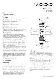
<strong>AUTOMATION</strong><strong>SYSTEM</strong>M3000HIGH-PERFORMANCEDIGITAL MOTION CONTROL <strong>SYSTEM</strong> FOR ELECTRICAND HYDRAULIC DRIVESWhat moves your world
2MOOG • Automation System • M3000
GENERALM3000CHAPTERPAGEOverview M3000 5Moog Servo Controller MSC 6Moog Servo Controller MSC II 12Moog Axis Control Software 18Analog Module QAIO 2/2 22Analog Module QAIO 16/4 24Digital Module QDIO 16/16 26Extension Module QEBUS-CAN 28Digital Extension Module RDIO 16/16 30EXCELLENCE IN DRIVE TECHNOLOGYFor over 50 years Moog has ranked amongst the leadingproviders of drive technology with a focus on theproduction and application of high performance products.Today, Moog offers innovative products using state of theart control techniques that contribute to the performanceimprovement of machines.Moog designs and manufactures products includingservovalves, servo-proportional valves, pumps, integratedhydraulic manifold systems, servomotors and drives, motioncontrollers and electronics and electromechanical actuators.Moog expertise and close collaboration with customersensure solutions that meet today’s toughest machinechallenges – contact us!Operator Panel RDISP 22 32Dialog Controller Display 34Global Support 39Our Quality Management System conforms to DIN EN ISO 9001.NOTICEThis catalog is for users with technical knowledge. To ensure that allnecessary characteristics for function and safety of the system are covered,the user must check the suitability of the products described herein. Productdescriptions provided herein are subject to changes that may be appliedwithout prior notification. In case of doubt, please contact Moog.Moog is a registered trademark of Moog Inc. and its subsidiaries. Unlessstated otherwise, all trademarks mentioned herein are the property of MoogInc. and its subsidiaries. For the full disclaimer refer to www.moog.com/literature/disclaimers.©Moog Inc. 2008. All rights reserved. Changes reservedFor the most current information, visit www.moog.com/industrialMOOG • Automation System • M3000 3
PRODUCT OVERVIEWM3000MoogServo Controller MSCMoog ServoController MSC IIMoog Axis ControlSoftwareAnalog ModuleQAIO 2/2Analog ModuleQAIO 16/4Digital ModuleQDIO 16/16Extension ModuleQEBUS-CANDigital ExtensionModule RDIO 16/16Operator PanelRDISP 22Dialog ControllerDisplay4MOOG • Automation System • M3000
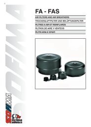
OVERVIEWM3000M3000 <strong>AUTOMATION</strong> <strong>SYSTEM</strong>M3000 is Moog’s digital motion control system, which offers high performance for hydraulic and electric drive products.This easy-to-use system offers rapid implementation and set-up to save users time and money.M3000 Automation SystemProgrammable Multi-Axis Controller• Moog Servo Controller (MSC)• Extension Modules• User DisplaysSoftware• Moog Axis Control Software (MACS)• Special function blocks for closedloopcontrolComponents• Servomotors and Servodrives• Servovalves• Servo-Proportional Valves• Radial Piston Pumps RKPPerformance• Cycle time for closed-loop axiscontrol as fast as 100 microseconds• Complex multi-axis (2 or more)motion control functions• High performance closed-loop controlfunctions designed by Moog expertsIntegration• Ethernet, USB, CAN bus, EIA/TIA 232onboard• Profibus-DP and EtherCAT optional• Various sensor inputs (e.g. SSI,incremental encoder) plus analogand digital input/output• Interface to multiple products,including Moog servodrives,servovalves, and pumps• One easy-to-use software for allM3000 products called MACS• All programming, debugging,simulation, parameterization,visualization, and tracing with onesoftware toolUse of Standards• User-friendly programming toolbased on CoDeSys, IEC 61131-3• All five IEC 61131-3 programminglanguages supported:- Function Block Diagram (FBD)- Instruction List (IL)- Sequential Function Chart (SFC)- Structured Text (ST)- Ladder Diagram (LD)• Latest graphical programminglanguage for easy closed-loopdesign Continuous Function Chart(CFC)• Standard protocols:CANopen, TCP/IP, DDE, OPC• A CoDeSys Automation Alliance(CAA) certified product• Motion control functions accordingto PLCopen standardScope of Supply and Services• Primary Feature: High PerformanceMotion Control• Plus: PLC Automation Solutions• Plus: Electric Motion Systems• Plus: Hydraulic Motion Systems• Plus: Training & Global Support ofSystem Solutions• Plus: Easy and Quick ImplementationMOOG • Automation System • M3000 5
MOOG SERVO CONTROLLERMSCBRIEF DESCRIPTIONMOOG SERVO CONTROLLER MSC• Freely programmable multi-axis controller• Programming with IEC 61131 development environmentMACS (Moog Axis Control Software)• Integrated PLC functionality• Realization of fast and precise controls(e.g. for position, speed and force)• Suitable for electrical and hydraulic drives• Freely definable controller structures with cycle timesfrom 400 μs• Hardware functionality can be parameterized via MACSsoftware• PowerPC-based processor• Memory: 4 MB RAM; 4 MB Flash EEPROMFEATURES• Tool-free assembly on DIN top-hat rail mounting• Simple wiring with terminal strips• Sustained short circuit protection for analog anddigital outputs• Overvoltage protection up to ±36 V ofanalog inputs and outputs• No parts subject to wear, no jumpers, no batteryor rechargeable battery• LEDs for status and error display• Wire fault monitoring for all digital sensor inputsand analog current outputs• Additional digital or analog inputs and outputswith M3000 extension modules• Simple connection of the M3000 modules viaextension bus (E-bus)• Profibus-DP slave as optionOVERVIEW: INTERFACES, CONNECTIONS AND LED’SProfibusDP-Slave(Option)Resetbutton6MOOG • Automation System • M3000
MOOG SERVO CONTROLLERMSCSET-UPLOCAL EXTENSION POSSIBILITIESWITH M3000 MODULES VIA E-BUS• Up to 7 additional M3000 modules can be connected tothe extension bus (E-bus) of the MSC• M3000 modules are put together and locked on thetop-hat rail. The E-bus connection is simply and reliablybuilt via the side connectors• In this way, further digital and/or analog inputs andoutputs can be added as required• The control and signal processing is done by the MSC.The connected extension modules do not require theirown intelligenceARRANGEMENT OF M3000 MODULES VIA E-BUSCAN bus cableMSC additional M3000 modules QCANDECENTRALIzed SET-UP• Additional M3000 modules can be independentlynetworked via the CAN bus• Extension modules can also be connected to eachdecentralized Moog Servo Controller MSC• In addition, M3000 remote modules (e.g. displays,digital inputs/outputs) can also be connected viathe CAN bus• Further components with CAN or CANopen interfacescan be networked. For this, Moog provides anextensive selection of motor controllers, hydraulicvalves and radial piston pumps• This enables a flexible set-up of automatic solutions• Further details can be found in the relevant catalogsARRANGEMENT OF M3000 MODULES VIA FIELD BUSField busMOOG • Automation System • M3000 7
MOOG SERVO CONTROLLERMSCINPUTS/OUTPUTS BASIC CIRCUIT DIAGRAMSDigital Inputs/OutputsVoltage supply of the digital I/O 24 V DC (18-36 V DC) SELV pursuant to DIN EN 60950-1Current consumption of the digital I/O0.3 A in idling; all digital outputs active: 4 A8 digital inputs and outputs Individually configurable in MACS as input or output.Inputs: type 1 (current-consuming) pursuant to IEC 61131-2Outputs: max. 0.5 ASustained short-circuit protection, thermal overload protectionWatchdog output:“Outputs enabled“ signalAnalog and digital outputs in operationIn the event of a fault, the watchdog output goes to ahigh impedance stateDIGITAL INPUTDIGITAL OUTPUTMSCMSCAnalog Inputs/OutputsVoltage supply to analog I/OVia internal DC/DC converter8 analog inputs 16 Bit; individually configurable in the MACS software as±10 V, ±10 mA or 4–20 mA; overvoltage protection up to ±36 V2 analog outputs 16 Bit; each ±10 V, additionally individually configurable in theMACS software as ±10 mA, ±50 mA or 4–20 mAOvervoltage protection up to ±36 V; short-circuit protectedanalog INPUT (CURRENT/VOLTAGE)MSCanalog outPUT (CURRENT/VOLTAGE)MSC8MOOG • Automation System • M3000
MOOG SERVO CONTROLLERMSCSENSOR INTERFACES DIMENSIONSReference for SensorsReference voltage outputSensor Interfaces2 Sensor interfaceseach configurable asa) Incremental encoderb) SSI transmitter+10 V; can bear up to max. 5 mAovervoltage protection up to ±36 V; short-circuit protectedSignals corresponding to TIA/EIA 422 (previously RS 422)Wire fault monitoring of inputsConfigurable in MACS software:a) Incremental encoderfour-edge evaluation, max. pulse frequency 8 MHzb) SSI sensor master or slavedata format: gray code or binary; data bits 8 to 32 Bittransmission frequency: 78 kHz to 5 MHzINCREMENTAL ENCODERSSI MASTERSSI SLAVEDIMENSIONSMOOG • Automation System • M3000 9
MOOG SERVO CONTROLLERMSCACCESSORIESLICENSE KEY(One license key is needed per MSC)The license key contains the runtime license for the MSC. According to the license key used, additional functionality of theMACS software is enabled for usage.Designation Scope of Functions Order numberControls(Color: Grey)• MACS runtime license forapplication program to DIN EN 60950-1• CoDeSys operators and standard IEC 61131 library• MSC hardware library• Moog control technique library• Interface library for TIA/EIA 232 and CAN bus• Support for OPC and DDE interfaces• Ethernet communication to MACS development environmentD138-002-001Motion(Color: green)All functions of "Controls" and additionally:• Motion control library according to PLCopen• Moog motion control function blocks• Library with transfer functions (Z functions)• CANopen and TCP/IP libraries• Profibus DP slave (depending on hardware option)D138-002-002System(Color: red)Program parts and/or complete application programs, producedspecifically upon customer’s requestIs stipulatedspecific to the orderAccessories Plug-in terminal strips (five 18-pole and one 9-pole are needed per module)Designation Description Order numberScrew terminal, 18-pole Up to max. conductor cross-section of 2.5 mm 2 (14 AWG) VK055-018Screw terminal, 9-pole Up to max. conductor cross-section of 2.5 mm 2 (14 AWG) VK055-009Spring-power clamp, 18-pole Up to max. conductor cross-section of 2.5 mm 2 (14 AWG) B95907-018Spring-power clamp, 9-pole Up to max. conductor cross-section of 2.5 mm 2 (14 AWG) B95907-00910MOOG • Automation System • M3000
MOOG SERVO CONTROLLERMSCTECHNICAL DATAModule DataDesignationDigital Control ModuleMoog Servo Controller MSCOrder numberD136-001-008 MSCD136-001-007 MSC with Profibus-DP slave interfaceConnection techniquePlug-in terminal strips for screwing or clampingAssemblyNS 35/7.5 mounting rail pursuant to EN 50022 (DIN top-hat rail)Dimensions W x D x H (mm) 160 x 170 x 85.5 (attachment dimension: W = 149/154.5)Temperature range+5 °C (+41 °F) to 55 °C (+131 °F) (operation) and-25 °C (-13 °F) to +70 °C (+158 °F) (storage)Mean temperature in operation for 24 hrs.: max. +50°C (+122°F)Relative air humidity10 % to 95 % (non-condensing)Operation heightMax. 2000 m (6500 feet); storage/transport max. 3000 m (9800 feet)ProcessorPowerPC Processor, 32 Bit, RISC architecture with floating point unitMemory4 MB Flash EEPROM; data maintenance: typically 10 yearsStandardsOperating equipment demands and examinations IEC 61131-2Interference emission / immunityEN 61000-6-4 / EN 61000-6-2, industrial partShock / vibration IEC 60068 part 2-27 / IEC 60068 part 2-6Protection class / protection systemIII / IP20Insulation strengthIEC 61131-2; test voltage 500 V DCEnergy SupplyVoltage supply of module electronics 24 V DC (18-36 V DC) SELV pursuant to DIN EN 60950-1Current consumption of module electronics 0.5 A / 2 A (idling / full load)Potential separationSeparate potentials for:module electronics, 24 V supply, digital inputs/outputs, EthernetInternal voltagesGenerated via internal DC/DC convertersBehavior at voltage failures/cut-off of supply voltageNecessary data are permanently stored (Flash EEPROM,data maintenance typically 10 years). If the supply voltage fails(
MOOG SERVO CONTROLLERMSC IIBRIEF DESCRIPTIONMOOG SERVO CONTROLLER (MSC II)The MSC II is a freely programmable multi-axis controllerthat facilitates rapid and precise control of processvariables such as position, speed, and power. It is suitablefor use with both electric and hydraulic drives.MSC II is offered in addition to MSC. Compared to the MSCit offers higher computation power, shorter cycle times andadditional field bus options, such as EtherCAT.The MSC II does not include analog inputs and outputs.The analog extension modules QAIO 16/4 or QAIO 2/2 arerecommended for applications where analog inputs andoutputs are required.FEATURES• Freely programmable multi-axis motion controller• Freely definable controller structures withcycle times from 100 µs• Very low jitter (variation of time base) for optimumclosed loop accuracy• Programming with IEC 61131 development environmentMACS (Moog Axis Control Software)• Integrated PLC functionality• Hardware functionality can be parameterizedvia MACS software• Tool-free assembly on DIN top-hat rail• Simple wiring with terminal strips• Sustained short circuit protection for digital outputs• No parts subject to wear, no jumpers, no batteryor rechargeable battery• LEDs for status and error display• Wire fault monitoring for all digital sensor inputs• Additional digital or analog inputs and outputswith M3000 extension modules• EtherCAT Realtime Ethernet interface as option• Profibus-DP slave as optionOVERVIEW: INTERFACES, CONNECTIONS AND LED’SState of DigitalI/OsTermination Resistorat LocalCANWideCAN-TransmissionActivityLocalCAN-TransmissionActivityE-Bus-TransmissionActivitySIO-Receiver ActivitySIO-TransmissionActivityActivated byApplication ProgramOutputs EnabledL1+ and +5 V OKWideCAN X1 + X3(internallyconnected 1:1)WideCAN X1 + X3(internallyconnected 1:1)Run/Stop/ResetSwitchLicense Key SlotUSBInterfaceRJ4510/100MBit/sLAN andProgrammingInterfaceRJ45 10/100MBit/sRealtime EthernetInterface (Option)SerialInterface SIOWire Fault Display forDigital Sensor InputsActivated by ApplicationProgram or Error DisplayField bus interface(Option)12MOOG • Automation System • M3000
MOOG SERVO CONTROLLERMSC IILOCAL EXTENSION POSSIBILITIESWITH M3000 MODULES VIA E-BUS• Up to 7 additional M3000 extension modules can beconnected to the extension bus (E-bus) of the MSC II• M3000 modules are put together and locked on thetop-hat rail. The E-bus connection is simply and reliablybuilt via the side connectors• In this way, further digital and/or analog inputs andoutputs can be added as required• The control and signal processing is done by the MSC II.The connected extension modules do not require theirown intelligenceARRANGEMENT OF M3000 MODULES VIA E-BUSCAN bus cableMSC II additional M3000 modules QCANDECENTRALIzed SET-UPAdditional M3000 modules can be independentlynetworked:• M3000 extension modules: With analog I/Osand digital I/Os• M3000 remote modules (e.g. displays, digital inputs/outputs)• Electrical servo drives (MSD Servo Controllers)• Servo and proportional valves with digital interfacelike Moog DIV (Digital Interface Valve),Moog ACV (Axis Control Valve)• Pumps with digital interface(Moog RKP-D Radial Piston Pumps)This enables a flexible set-up of automation solutions.Further details can be found in the relevant catalogs.ARRANGEMENT OF M3000 MODULES VIA FIELD BUSField busMOOG • Automation System • M3000 13
MOOG SERVO CONTROLLERMSC IIINPUTS/OUTPUTS BASIC CIRCUIT DIAGRAMSDigital Inputs/OutputsVoltage supply of the digital I/O 24 V DC (18-36 V DC) SELV pursuant to DIN EN 60950-1Current consumption of the digital I/O0.3 A in idling; all digital outputs active: 2 A4 digital inputs and outputs Individually configurable in MACS as input or outputInputs: type 2 (current-consuming) pursuant to IEC 61131-2Outputs: max. 0.5 ASustained short-circuit protected, thermal overload protectionWatchdog output:"Outputs enabled" signalOutputs in operation. In the event of a fault,the watchdog output goes to a high impedance stateDigital inputDigital OutputMSC IIMSC II14MOOG • Automation System • M3000
MOOG SERVO CONTROLLERMSC IISENSOR INTERFACES DIMENSIONSSensor Interfaces4 Sensor interfaces each configurable asa) Incremental encoder• Standard• Pulse train• Frequency measurementb) SSI transmitterSignals corresponding to TIA/EIA 422 (previously RS 422)with protection against 24 Volt. Wire fault monitoring ofinputs. Configurable in MACS software:a) Incremental encoderfour-edge evaluation, max. pulse frequency 8 MHzb) SSI sensor master or slave data format: gray or binarycode; data bits 8 to 32 Bit;transmission frequency: 78 kHz to 5 MHzIncremental EncoderMSC IISSI MasterMSC IISSI SlaveMSC IIDIMENSIONS124 mm (4.48 in)113 mm (4.45 in)170 mm (6.69 in)Height:• 85.5 mm (3.37 in)without License Key• 102 mm (4.02 in)with License KeyMOOG • Automation System • M3000 15
MOOG SERVO CONTROLLERMSC IIACCESSORIESLICENSE KEY(One license key is needed per MSC II)The license key contains the runtime license for the MSC II. According to the license key used, additional functionality ofthe MACS software is enabled for usage.Designation Scope of Functions Order numberControls(Color: Grey)MACS runtime license for application program• CoDeSys operators and standard IEC 61131 library• MSC II hardware library• Moog control technique library• Interface library for TIA/EIA 232 and CAN bus• Support for OPC and DDE interfaces• Ethernet communication to MACS developmentenvironmentD138-002-001Motion(Color: green)System(Color: red)All functions of "Controls" and additionally:• Motion control library according to PLCopen• Moog motion control function blocks• Library with transfer functions (Z functions)• CANopen and TCP/IP libraries• Profibus-DP slave (depending on hardware option)• EtherCAT master (depending on hardware option)Program parts and/or complete application programs,produced specifically upon customers requestD138-002-002Is stipulated specific to theorderAccessories Plug-in terminal strips (four 10-pole and two 9-pole are needed per module)Designation Description Order numberScrew terminal, 9-pole Up to max. conductor cross-section of 2.5 mm 2 (14 AWG) VK055-009Spring-power clamp, 9-pole Up to max. conductor cross-section of 2.5 mm 2 (14 AWG) B95907-009Spring-power clamp, 10-pole Up to max. conductor cross-section of 0.5 mm 2 (20 AWG) CA45260-01016MOOG • Automation System • M3000
MOOG SERVO CONTROLLERMSC IITECHNICAL DATAModule DataDesignationDigital Control ModuleMoog Servo Controller II (MSC II)Order number D136-002-002 MSC IID136-002-001 MSC II : As D136-002-002but additional Profibus-DP interfaceD136-002-003 MSC II : As D136-002-002but additional dual EtherCAT Master interfaceConnection techniquePlug-in terminal strips for screwing or clampingAssemblyNS 35/7.5 mounting rail pursuant to EN 50022 (DIN top-hat rail)Dimensions W x D x H (mm) 124 × 170 × 85.5 (attachment dimension: W = 113 / 118.5)Temperature range+5 °C (+41 °F) to 55 °C (+131 °F) (operation) and-25 °C (-13 °F) to +70 °C (+158 °F) (storage)Mean temperature in operation for 24 hrs.: Max. +50 °C (+122 °F)Relative air humidity10 % to 95 % (non-condensing)Operation heightMax. 2000 m (6500 feet); storage/transport max. 3000 m (9800 feet)ProcessorPowerPC Processor, 32 Bit, RISC architecture with floating point unitMemory128 MB RAM, 32 MB Flash EEPROM;data maintenance: typically 10 yearsStandardsOperating equipment demands and examinations IEC 61131-2Interference emission / immunityEN 61000-6-4 / EN 61000-6-2, industrial partShock / vibration IEC 60068 part 2-27 / IEC 60068 part 2-6Protection class / protection systemIII / IP20Insulation strengthIEC 61131-2; test voltage 500 V DCEnergy SupplyVoltage supply of module electronics 24 V DC (18-36 V DC) SELV pursuant to DIN EN 60950-1Current consumption of module electronics 0.5 A / 2 A (idling / full load)Potential separationSeparate potentials for: Module electronics, 24 V supply,digital inputs/outputs, EthernetInternal voltagesGenerated via internal DC/DC convertersBehavior at voltage failures /cut-off of supply voltageInterfacesEthernet (100BaseT)EtherCAT (optional)Necessary data are permanently stored(Flash EEPROM, data maintenance typically 10 years)100 MBit/s with 8-pole RJ45 connectionDual EtherCAT Master Interface, Slave in preparationProfibus-DP slave (optional)Transmission rate adjustable up to 12 MBit/s2 independent CAN interfacesTransmission rate adjustable, 10 kBit/s to 1 MBit/s"WCAN"WCAN: 2 D-Sub "WCAN" connectors on the front cover(are connected internally 1:1)"LCAN"LCAN: in the side Q-connectors2 USB 1.1 interfaces Host interface(s) via USB-A connector"SIO" on front cover (TIA/EIA 232)For free use in the application programExtension bus (E-bus)Q-connectors on right and left of module for connecting upto 7 additional M3000 modulesContains a serial bus (5 to 10 MBit/s) and the LCAN busMOOG • Automation System • M3000 17
Moog Axis Control SoftwareMACSBRIEF DESCRIPTIONGENERALThe Moog Axis Control Software (MACS) offers astate-of-the-art development environment for solvingdemanding control tasks on the basis of the IEC 61131standard.MACS includes tools for:• Programming• Testing and optimizing• Debugging• Documentation• Visualization• ConfigurationFEATURES• Extensive libraries with Moogfunction blocks, based on50 years of experience in electricand hydraulic driveengineering• Freely programmable controllerstructures• Maximum flexibility by a complete scope of functions inall IEC 61131 programming languages• Simultaneous realization of control, regulation and PLCapplications in one application program• Open standard interfaces for communication onmachine and process guidance levels• Motion control functions corresponding to PLCopenstandardMACSINTERFACESProcess guidance level:• OPC server• DDE interfaceMachine level:• CAN• CANopen• Ethernet TCP/IP• Profibus DP• TIA/EIA 232• EtherCATYOUR BENEFITS• Quick project realization• Low programming efforts• One tool for programming, visualizing, documentation• Compatibility to products of member companies of theCoDeSys Automation Alliance18MOOG • Automation System • M3000
Moog Axis Control SoftwareMACSPROGRAMMING LANGUAGESPROGRAM CREATION• All IEC 61131 programming languages and CFC(Continuous Function Chart)• Full scope of function in all programming languages,provides maximum flexibility in creation of userprograms• Each module can call other modules regardless of theprogramming language they have been created inEDITORS• Context-sensitive input help• Automatic formatting• Context menus in all editors• Syntax coloring• Multi-level undo/redo• Display of the current values of all variablesin online operationCONTINUOUS FUNCTION CHART (CFC)FUNCTION BLOCK DIAGRAM (FBD)STRUCTURED TEXT (st)SEQUENCE FUNCTION CHART (SFC)LADDER DIAGRAM (LD)INSTRUCTION LIST (IL)MOOG • Automation System • M3000 19
Moog Axis Control SoftwareMACSLIBRARIESTECHNICAL DATAMACS is based on CoDeSys which is the most modernIEC 61131 programming system. It has been extended in theareas of control technique and motion control by Moog. Inthis way, even complex automation projects can besimplified.Overview: Scope of Function of the Moog LibrariesRegulation and Control Technique• Controller- I, D, PID standard, PID extended• Filter- high-pass, low-pass• Transmission functions- continuous, time discrete• Non-linear functions- dead band, non-linear- dual-gain, look-up table• Simulation of control routes- PT1, PT2• Function generator• Signal delay• Counter, timerPLCopen function blocksAccording to the specification “function blocksfor motion control” for single and multi-axisapplications:• Absolute and relative positioning• Speed functions• Homing• Cam functions• Gearbox functionsCommunication, Ethernet, CAN and TIA/EIA 232• Initialization• Transmission and receiving of dataHardware Related Functions• Signal conditioning for analoginputs/outputs and position sensor• Evaluation of status information• Time evaluation• Monitoring- temperature, watchdog, wire breakageDesignation Description OrderMACS(Moog Axis Control Software)MACS HMI(Human Machine Interface)Development environment pursuant to IEC 61131One license per developerVisualization versionFor full-screen display of visualizations whichwere created with MACS.Without development environment.One license per machine.Software maintenance contract Includes support and updates for 1 year B95914-0011 license: D138-001-00110 licenses: D138-001-0101 license: D138-003-00110 licenses: D138-003-01020MOOG • Automation System • M3000
Moog Axis Control SoftwareMACSTHE COMPONENTSVISUALIZATION• Commissioning tool• Creation of visualizations for end usersHARDWARE CONFIGURATION• Configuration of all M3000 moduleson one screenOSCILLOSCOPE• Recording of up to 20 channels• Various triggering possibilitiesDOCUMENTATION• Automatic creation of the project documentation with allcomponentsDEBUGGING• Break points• Single step/single cycle• Writing and forcing of variables• Simulation possible without hardware• Display of all the current valuesTASK CONFIGURATION• Enables division of the application program into a numberof tasks• Call of the tasks optionally time-based (cyclic) orevent triggered• Priority and time base of each task adjustableMOOG • Automation System • M3000 21
analog modulEQAIO 2/2BRIEF DESCRIPTIONGENERALFeaturesThe QAIO 2/2 analog module is used for local extension ofthe inputs and outputs (I/O) of the Moog Servo ControllerMSC or MSC II. The analog levels are identical to the levelsof the MSC.The module is mounted on a DIN top-hat rail and directlyconnected to an MSC or MSC II via the internal extensionbus (E-bus).Analog I/O extension module withpulse input.• 2 analog inputs• 2 analog outputs• 1 reference voltage output +10 V• Pulse input• Connection via E-busOUTPUTS/INPUTSCONFIGURATION• 2 analog inputs, each configurable in the MACSdevelopment environment as ±10 V, ±10 mA or 4-20 mA.The inputs are converted in multiplex operation• 1 reference voltage output:The reference voltage source provides a shortcircuit protected voltage of +10 V• 2 analog outputs, each ±10 V, additionallyindividually configurable in the MACS software as±10 mA, ±50 mA or 4–20 mA with wire faultmonitoring• 1 pulse input 24 V useable as counter input orfrequency measurement inputMODULE STATUS LEDSOn the front, 4 LEDs provide information about the statusof important module functions.The configuration of the analog I/O is carried out persoftware via the central control configuration in the MoogAxis Control Software (MACS) development environment.Either the two analog inputs or the pulse input can be used.ACTUATIONThe I/O of the analog extension module is actuateddirectly from an MSC or MSC II (not D136X001-001 andD136E001-001) via the extension bus (E-bus). All input- andoutput-data are transferred within one cycle of the E-bus.E-BUSOne MSC or MSC II can be extended with a maximum of7 QAIO 2/2-AV modules. It is not possible to combine itwith QAIO 16/4 on one E-bus segment.analog input (current/voltage)QAIO 2/2analog output (current/voltage)QAIO 2/2Aix+±10 VCxaDAoxaVoltageACxbRLVoltageAix-AGNDFilterMUXAD±10 mAAGNDAoxbCurrentRLAix+4–20 mAAGNDCxaCxb±50 mACurrentAix-FilterAGNDOutput CurrentMonitoringPUlSe input positive switchingPUlSe input ground switchingSignal-SourceQAIO 2/2Signal-SourceQAIO 2/2L2+L2+24 V DCOEto evaluationOpto-Decoupling24 V DCOCto evaluationOpto-DecouplingM2M222MOOG • Automation System • M3000
analog modulEQAIO 2/2TECHNICAL DATAModule DataOrder numberQAIO 2/2-AV I/O extension moduleD137-001-011Connection to M3000 modulesVia E-Bus (10 MHz); please note:- It is not possible to connect the module to an MSC D136X001-001or D136E001-001- Combination with QAIO 16/4 A on one E-bus segment is not possibleConnection techniquePlug-in terminal strips for screwing or clampingMountingMounting rail NS 35/7.5 pursuant to EN 50022 (DIN top-hat rail)4 module status LEDs Module functions and diagnosisDimensions, W x H x D124 x 170 x 85.5 (attachment dimension: W = 113/118.5) mm4.88 x 6.69 x 3.37 (attachment dimension: W = 4.45/4.67) inchTemperature range+5 °C (+41 °F) to +55 °C (+131 °F) (operation) and-25 °C (-13 °F) to +70 °C (+158 °F) (storage)Mean temperature in operation for 24 hrs.: max. +50 °C (+122 °F)Relative air humidity10 % to 95 % (non-condensing)Operation heightMax. 2000 m (6500 ft); storage/transport max. 3000 m (9800 ft)StandardsOperating equipment demands and examinations IEC 61131-2Interference emission / immunityEN 61000-6-4 / EN 61000-6-2, industrial partShock / vibration IEC 60068 part 2-27 / IEC 60068 part 2-6Protection class / protection systemIII / IP20Insulation strengthIEC 61131-2; test voltage 500 V DCEnergy SupplyVoltage supply of module electronics 24 V DC (18-36 V DC) SELV pursuant to DIN EN 60950-1Current consumption of module electronics Max. 0.25 APotential separationSeparate potentials for: module electronics, 24 V energy supply, pulse inputInternal voltagesInternally generated via DC/DC convertersProtection against reverse polarityYesAnalog Inputs/Outputs2 analog inputs 16 Bit; individually configurable in the MACS development environmentas ±10 V, ±10 mA or 4–20 mA; overvoltage protection up to ±36 V2 analog outputs 16 Bit; each ±10 V, additionally individually configurable in the MACSdevelopment environment as ±10 mA, ±50 mA or 4–20 mAOvervoltage protection up to ±36 V; short-circuit protectedReference for sensorsReference voltage output+10 V; max. load: 5 mAOvervoltage protection up to ±36V; short circuit protectedPulse inputPulse input 24 V digital input can be used as input pursuant to IEC 61131-2 type 1positive switching (input OE) or ground switching (input OC)Accessories Plug-in terminal strips ( two 18-pole and one 9-pole are required per module)Designation Description Order numberScrew terminal 18-pole Up to max. conductor cross-section of 2.5 mm 2 (14 AWG) VK055-018Screw terminal 9-pole Up to max. conductor cross-section of 2.5 mm 2 (14 AWG) VK055-009Spring latch clamp 18-pole Up to max. conductor cross-section of 2.5 mm 2 (14 AWG) B95907-018Spring latch clamp 9-pole Up to max. conductor cross-section of 2.5 mm 2 (14 AWG) B95907-009Detailed information and integration tips can be obtained from the user manual.MOOG • Automation System • M3000 23
analog modulEQAIO 16/4BRIEF DESCRIPTIONGENERALThe QAIO 16/4 analog module is used for local extension ofthe inputs and outputs (I/O) of the Moog Servo ControllerMSC or MSC II.The module is mounted on a DIN top-hat rail and directlyconnected to an MSC or MSC II via the internal extension bus(E-bus).FeaturesAnalog I/O extension module• QAIO 16/4-V 16 voltage inputs ±10 V; orQAIO 16/4-A 16 current inputs ±20 mA• 4 voltage outputs, ±10 V• 1 reference voltage output +10 V• Connection via E-busINPUTS/OUTPUTS• 16 voltage or current inputs:The input channels are converted in multiplex operation.The measurement range is ±10 V (QAIO 16/4-V)or ±20 mA (QAIO 16/4-A)• 4 voltage outputs:The output channels provide a voltage signal in therange of ±10 V. The maximum output current is 5 mA(overload protection)• 1 reference voltage output:The reference voltage source provides a short circuitprotected voltage of +10 VCONFIGURATIONThe configuration of the analog I/O is carried out persoftware via the central control configuration in the MoogAxis Control Software (MACS) development environment.MODULE STATUS LEDSOn the front, 4 LEDs provide information about the statusof important module functions.ACTUATIONThe I/O of the analog extension module is actuated directlyfrom an MSC or MSC II via the extension bus (E-bus).E-BUSOne MSC or MSC II can be extended with a maximum of7 modules (e.g. QAIO or QDIO).BASIC CIRCUIT DIAGRAM, ANALOG INPUTBASIC CIRCUIT DIAGRAM, ANALOG OUTPUT24MOOG • Automation System • M3000
analog modulEQAIO 16/4TECHNICAL DATAModule DataOrder numberConnection to M3000 modulesConnection techniqueConnection of the I/OMountingAnalog I/O extension moduleQAIO 16/4-V: D137-001-007; QAIO 16/4-A: D137-001-006Via E-bus (5 MHz)Plug-in terminal strips for screwing or clamping3-conductor front wiring4 module status LEDs Module functions and diagnosisDimensions, W x H x DTemperature rangeRelative air humidityMounting rail NS 35/7.5 according to EN 50022 (DIN-top hat rail)124 x 170 x 85.5 (attachment dimension: W = 113 / 118.5) mm;4.88 x 6.69 x 3.37 (attachment dimension W = 4.45/4.67) inch+5 °C (+41 °F) to +50 °C (+122 °F) (operation) and-25 °C (-13 °F) to +70 °C (+158 °F) (storage)10 % to 95 % (non-condensing)StandardsInterference emission / immunityProtection class / protection systemInsulation strengthEN 61000-6-4 / EN 61000-6-2, industrial portionIII / IP20IEC 61131-2; test voltage 500 V DCEnergy SupplyVoltage supply of module electronics 24 V DC (18-32 V DC) SELV pursuant to DIN EN 60950-1Current consumption of module electronics Max. 0.3 AVoltage supply of the analog I/OInternally supplied via DC/DC convertersPotential separationYes, opto-decoupled towards E-bus;No separation between energy supply and analog channelsProtection against reverse polarityYesAnalog Inputs16 analog inputs, differential QAIO 16/4-V: ±10 V; QAIO 16/4-A: ±20 mAResolution12 Bit (multiplex operation)Input impedance in signal areaQAIO 16/4-V: 10 MΩ; QAIO 16/4-A: 50 ΩAnalog Outputs4 analog outputs ±10 VResolution12 BitOutput currentMax. 5 mALoad resistanceMin. 2 kΩIn-phase area±2 VReference Voltage SourceReference voltage+10 V DC sustained short circuit protectionLoad currentMax. 5 mAPrecision 0.1 %Accessories Plug-in terminal strips (5 are required per module)Designation Description Order numberScrew terminal, 18-pole Up to max. conductor cross-section of 2.5 mm 2 (14 AWG) VK055-018Spring-power clamp, 18-pole Up to max. conductor cross-section of 2.5 mm 2 (14 AWG) B95907-018Detailed information and integration tips can be obtained from the user manual.MOOG • Automation System • M3000 25
digital modulEQDIO 16/16BRIEF DESCRIPTIONGENERALThe QDIO digital module is used for extension of the localinputs and outputs (I/O) of the Moog Servo Controller MSCor MSC II.The module is mounted on a DIN top-hat rail and directlyconnected to an MSC or MSC II, or a remote digital I/Omodule (RDIO) via the internal extension bus (E-bus).FeaturesDigital I/O extension moduleQDIO 16/16-0.5: I/O positive switchingQDIO 16/16-0.5N: I/O zero switching• 16 digital inputs 24 V• 16 digital I/O, 24 V, individually configurableas an input or an output• Connection via E-busCONFIGURATIONThe configuration of the digital I/O is carried out persoftware via the central control configuration in the MoogAxis Control Software (MACS) development environment.STATUS LEDsLEDs on the front provide information about the status ofthe I/O. The arrangement of the LEDs corresponds to the I/Oconnections.ACTUATIONThe I/O of the digital extension module are actuated directlyfrom an MSC, MSC II or RDIO via the extension bus (E-bus).E-BUSOne MSC or MSC II can be extended with a maximum of7 modules (e.g. QDIO or QAIO). Further digital I/O can beactuated via RDIO modules, which are connected with anMSC or MSC II via CANopen.BASIC CIRCUIT DIAGRAM, DIGITAL INPUTPlus switchingZero switchingBASIC CIRCUIT DIAGRAM, DIGITAL OUTPUTPlus switchingZero switching26MOOG • Automation System • M3000
digital REMOTE I/OEXTENSION modulEQDIO 16/16TECHNICAL DATAModule DataOrder number / DesignationTypes of inputs/outputsConnection to M3000 modulesConnection techniqueConnection of the I/OAssemblyStatus LEDsDimensions W x H x DTemperature rangeRelative air humidityDigital Remote I/O Extension ModuleQDIO 16/16-0.5: D137-001-005QDIO 16/16-0.5N: D137-001-004QDIO 16/16-0.5: plus switchingQDIO 16/16-0.5N: zero switchingVia E-bus (max. 10 MHz)Plug-in terminal strips for screwing or clamping3-conductor front wiringMounting rail NS 35/7.5 pursuant to EN 50022 (DIN top-hat rail)1 Status LED per I/O124 x 170 x 85.5 (attachment dimension: W = 113/118.5) mm;4.88 x 6.69 x 3.37 (attachment dimension W = 4.45/4.67) inch+5 °C (+41 °F) to +50 °C (+122 °F) (operation) and-25 °C (-13 °F) to +70 °C (+158 °F) (storage)10 % to 95 % (non-condensing)StandardsInterference emission / immunityProtection class / protection systemInsulation strengthEN 61000-6-4 / EN 61000-6-2, industrial portionIII / IP20IEC 61131-2; test voltage 500 V DCEnergy SupplyVoltage supply of module electronics 24 V DC (18-32 V DC) SELV pursuant to DIN EN 60950-1Current consumption of module electronics Max. 0.15 AVoltage supply of the digital I/O24 V DC (SELV), divided into 6 groupsCurrent consumption of the digital I/O At U = +24 V DC in idling, max. 300 mA; all digital I/O active, approx. 8 APotential separationYes, between E-bus and digital I/ODigital Inputs/OutputsNumber of inputs 16Number of inputs/outputs16, each useable as inputs or outputsOutput currentMax. 0.5 AShort-circuit / reverse polarity protection Yes / yes, all digital outputsAccessories Plug-in terminal strips (6 are required per module)Designation Description Order numberScrew terminal, 18-pole Up to max. conductor cross-section of 2.5 mm 2 (14 AWG) VK055-018Spring-power clamp, 18-pole Up to max. conductor cross-section of 2.5 mm 2 (14 AWG) B95907-018Detailed information and integration tips can be obtained from the user manual.MOOG • Automation System • M3000 27
EXTENSION MODULEQEBUS-CANBRIEF DESCRIPTIONGENERALThe QEBUS-CAN module is designed for using the LocalCANbus for external CAN bus nodes.The LocalCAN bus is integrated in the extension bus plugand is accessed via the QEBUS-CAN module by means oftwo D-Sub mating connectors.Furthermore, the QEBUS-CAN module offers the option ofusing a jumper to connect/disconnect a CAN terminationresistor.The module is mounted onto a DIN top-hat rail and isdirectly attached to an MSC or MSC II or extension modulevia the Q-connector.FEATURES• The QEBUS-CAN module does not countas an E-bus node, it can be used inaddition to the maximum numberof E-bus modules• The module can be placed either at thefar left or far right in an E-bus segment• The module has a smaller width than theQDIO, QAIO and RDIO modules• The module does not need to be configured• The E-bus does not pass through the module• Both D-Sub mating connectors are identically wired• The CAN bus can be connected to a power supply via X1CONNECTORSX1X11 21 2J1J2J1J2X2X3X2X3J3J3Jumper positionCAN bus not terminatedJumper positionCAN bus terminatedCONNECTION ASSIGNMENTSX1 CAN supply connection assignmentsNr. Assignment Connection1 CAN_V+ CAN bus supply2 DGND Digital groundConnection assignment LocalCAN X2 and X3Nr. Assignment Connection12 CAN-L CAN-3 DGND Digital ground4567 CAN-H CAN+89 CAN_V+ CAN bus supplyNon assigned contacts are not connected.28MOOG • Automation System • M3000
EXTENSION MODULEQEBUS-CANTECHNICAL DATAModule DataDesignationOrder numberConnection to M3000 modulesConnection technologyInstallationDimensions W x Hx DTemperature rangeRelative humidityOperating heightQEBUS-CAN Extension ModuleQEBUS-CAND137-001-010Via Q-connectorOptional CAN power supply: plug-in terminal strip for screwing orclamping, CAN bus: 2 D-Sub connectionsMounting rail NS 35/7.5 according to EN 50022 (DIN top-hat rail)65 x 170 x 85.5 (attachment dimension W = 59.5) mm2.55 x 6.69 x 3.37 (attachment dimension W = 2.34) inch+5 °C (+41 °F) to +55 °C (+131 °F) (operation) and -25 °C (-13 °F) to+70 °C (+158 °F) (storage).Mean temperature during operation over 24 hours: max. 50 °C (+122 °F)10% to 95% (non-condensing)Max. 2000 m (6500 feet); storage/transport: max. 3000 m (9800 feet)StandardsOperational equipment demandsIEC 61131-2and examinationsInterference emission / immunityEN 61000-6-4 / EN 6100-6-2, industrial rangeShock / vibration IEC 60068 Part 2-27 / IEC 60068 Part 2-6Protection class / protection systemIII / IP20Insulation strengthIEC 61131-2; test voltage 500 V DCEnergy supplyVoltage supply of module electronicsNone (passive module)InterfacesQ-connector Contains the LocalCAN bus of the MSC ;E-bus is not passed through the moduleLocalCAN Bus2 D-Sub connections (these are connected internally); 120Ω terminationresistor can be connected / disconnected with jumper J3Accessories Plug-in terminal strip (1 piece per module)Designation Description Order numberScrew terminal, 2-pole Up to max. conductor cross-section of 2.5 mm 2 (14 AWG) VK055-002Spring-power clamp, 2-pole Up to max. conductor cross-section of 2.5 mm 2 (14 AWG) B95907-002CAN connection cable,3 meters / 9.8 feetOne side: 9-pole D-Sub plug-in connectorwith pin contacts (to DIN 41652)Other side: 9-pole D-Sub plug-in connectorwith jack contacts (to DIN 41652)B95863-001CAN connection cable,10 meters / 32.8 feetOne side: 9-pole D-Sub plug-in connectorwith pin contacts (to DIN 41652)Other side: 9-pole D-Sub plug-in connectorwith jack contacts (to DIN 41652)Detailed information and integration tips can be obtained from the user manualB95863-002MOOG • Automation System • M3000 29
DIGITAL REMOTE I/OEXTENSION MODULERDIO 16/16BRIEF DESCRIPTIONGENERALThe RDIO digital module is used as a remote extensionof the local inputs and outputs (I/O) of a Moog ServoController MSC or MSC II.The module is mounted on a DIN top-hat rail andconnected to an MSC or MSC II via CAN.FeaturesDigital I/O extension module• 16 digital inputs 24 V• 16 digital I/O 24 V, individually configurable as an inputor an output• CANopen slave complying with CiA DS 401INTERFACEThe Moog Axis Control Software (MACS) includes a librarywith function blocks to interface the RDIO via CANopen.This ensures simple integration into the Moog M3000control system, e.g. to Moog Servo Controller MSC and MSC II.STATUS-LEDsLEDs on the front provide information about the status ofeach I/O. The arrangement of the LEDs corresponds to theI/O connections.canopen INTERFACEThe I/Os are accessed via CANopen interface.The RDIO can be extended locally by connecting up to6 QDIO modules. The I/Os of the QDIO modules are alsoaccessed via CANopen interface of the RDIO.HARDWARE CONFIGURATION• No modules shall be connected to the left Extensionmodule-Bus(E-Bus) connector of the module• The CAN interface is only accessible via the CANconnectors on the front cover• Up to 6 QDIO modules can be connected to the rightE-Bus connector of the module• Several RDIOs can be connected via CAN connectorBASIC CIRCUIT DIAGRAM, DIGITAL INPUTBASIC CIRCUIT DIAGRAM, DIGITAL OUTPUT30MOOG • Automation System • M3000
DIGITAL REMOTE I/OEXTENSION MODULERDIO 16/16TECHNICAL DATAModule DataDigital Remote I/O Extension ModuleOrder number / Designation D137-002-001 / RDIO 16/16-0.5Types of inputs/outputsInterfacesConnection techniqueConnection of the I/OAssemblyStatus LEDsDimensions W x H x DTemperature rangeRelative air humidityPlus switchingCAN, E-BusPlug-in terminal strips for screwing or clamping3-conductor front wiringMounting rail NS 35/7.5 pursuant to EN 50022 (DIN top-hat rail)1 Status LED per I/O124 x 170 x 85.5 (attachment dimension: W = 113/118.5) mm4.88 x 6.69 x 3.37 (attachment dimension: W = 4.45/4.67) inchOperation: 5 °C to 50 °C (41 °F to 122 °F)Storage: -25 °C to 70 °C (-13 °F to 158 °F)10 % to 95 % (non-condensing)StandardsInterference emission / immunityProtection class / protection systemInsulation strengthEN 61000-6-4 / EN 61000-6-2, industrial portionIII / IP20IEC 61131-2; test voltage 500 V DCEnergy SupplyVoltage supply of module electronics 24 V DC (18-32 V DC) SELV pursuant to DIN EN 60950-1Current consumption of module electronics Max. 0.15 AVoltage supply of the digital I/O24 V DC (SELV), divided into 6 groupsCurrent consumption of the digital I/O At U = 24 V DC in idling, max. 300 mA;all digital I/O active, approx. 8 APotential separationYes, between CAN and digital I/ODigital Inputs/OutputsNumber of inputs 16Number of inputs/outputs16, each useable as input or outputOutput currentMax. 0.5 AShort-circuit / reverse polarity protection Yes / yes, all digital outputsAccessories Connectors (six 18-poled are needed per module)Designation Description Order numberScrew terminal, 18-pole Up to max. conductor cross-section of 2.5 mm 2 (14 AWG) VK055-018Spring-power clamp, 18-pole Up to max. conductor cross-section of 2.5 mm 2 (14 AWG) B95907-018CAN connection cable,3 meters / 9.8 foot9-pole D-sub plug-in connection;pin contacts to jack contactsB95863-001CAN connection cable,10 meters / 32.8 footCAN bus termination resistor 120ΩCAN bus termination resistor 120Ωwith grounding9-pole D-sub plug-in connection;pin contacts to jack contacts9-pole D-sub plug-in connection withjack contacts9-pole D-sub plug-in connection with pin contacts;CAN-GND connected to SL/PEDetailed information and integration tips can be obtained from the user manual.B95863-002B95864-001B95865-001MOOG • Automation System • M3000 31
OPERATOR PANELRDISP 22BRIEF DESCRIPTIONGENERALThe operator panel RDISP 22 is designed for supervisionand control of machines and processes.Its main advantage is the easy and fast creation ofvisualization screens with text and graphical elements andvisualization structures.FEATURES• LCD-Display to display textand graphics with240 x 64 points and LEDbackground lighting• 8 function keys and 8 LEDs for signal display• Numeric keypad for value input• 22 keys all togetherDISPLAYThe LCD display with graphics capabilities permitsoptimum graphical display of your visualization solution.Up to 8 x 40, 4 x 20, 2 x 10 characters per page and anycombination of these, pictograms and graphical displayimages in BMP format can be displayed.Contrast and brightness can be adjusted via the programor keys.KEYSThe keys are built as push buttons and are covered by a robustfoil. They grant a good haptic feedback.INTERFACESCAN, CANopen, TIA/EIA 232IMAGES AND MESSAGESThe RDISP22 offers the display types ’images’ and´messages’. They can be activated independently.• Images:Images are graphical elements (pictograms, BMP files),in which text and variables are displayed both numericallyand graphically or as bar charts or as X/Y charts.A menu structure out of different images can be definedby the programmer. An image can be selected by animage number or via a menu structure by using keys• Messages:Messages can be inserted into a page in addition as textswith variables. Messages are activated by using themessage numberMEMORYAll data (parameters, images and messages) are stored inthe maintenance-free flash memory.INTERFACEThe Moog Axis Control Software (MACS) includes a librarywith function blocks to interface the RDISP via CANopen.This ensures simple integration into the Moog M3000control system, e.g. to Moog Servo Controller MSC or MSC II.LABELINGThe function keys can be labeled freely. This is done byusing strips of paper and inserting them between the keysand the front cover.PROGRAMMINGProgramming is carried out on the PC via an userfriendly editor. Easy operation enables clear and quickimplementation. Programming of menus, menu structures,message texts and multi-language display is easy to achievewith the CPRDISP PC editor.AccessoriesDesignation Description Order numberCPRDISP PC based editor to build menu pages D138-006-001CAN connection cable, 3 meters / 9.8 foot 9-pole D-sub plug-in connection;pin contacts to jack contactsB95863-001CAN connection cable, 10 meters / 132.8 foot 9-pole D-sub plug-in connection;B95863-002pin contacts to jack contactsCAN bus termination resistor 120Ω 9-pole D-sub plug-in connection with jack contacts B95864-001CAN bus termination resistor 120Ωwith grounding9-pole D-sub plug-in connection withpin contacts; CAN-GND connected to SL/PEB95865-00132MOOG • Automation System • M3000
OPERATOR PANELRDISP 22TECHNICAL DATAModule DataOperator PanelOrder number / Designation D137-004-001 / RDISP 22HousingIntegrated caseDimensions: W x D x H in mm (in.)196 x 129 x 53 (7.72 x 5.08 x 2.09 in.) (front with plug)Mounting hole: W x D in mm (in.)187 x 120 (7.36 x 4.72 in.)Temperature range-10 °C to 60 °C (14 °F to 140 °F)Relative air humidity10 % to 95 % (non-condensing)StandardsInterference emission / immunityEN 61000-6-4 / EN 61000-6-2, industrial portionProtection class / protection systemIII / IP65 front side, IP20 rear sideShock / vibration IEC 60068 Part 2-27 / IEC 60068 Part 2-6Energy SupplyVoltage supplyCurrent consumption at 24 V DCFuseConnection of power supply24 V DC (17-32 V DC) SELV with reverse voltage protection500 mA max. depending on display brightnessElectronic with automatic reset6-pole AMP crimp connectorDisplayDisplayLCD-Supertwist 240 x 64 points; LED background lightingNumber of characters per line max/min 40 / 10Line height 2-4-8 lines in mm (in.)14 / 7 / 4 (0.55 / 0.28 / 0.16 in.)Standard character setIBM set 2 and Cyrillic, other characters possibleKeysPush buttonsNumber of keys22 (including numeric keypad)Key topAluminum disc behind polyester cover; secured against vandalismRearGalvanized steel plate with clamping lidWeight1.4 kg (3.08 lbs.)FunctionsMenu structuresContrast and brightnessCharacter attributesProgrammingValue entryVariablesVariable typesMemoryInterface to PC Editor (CPRDISP)Interface to controller (e.g. MSC, MSC II)Tree structure or other structureAdjustable using keys and programFlashing, normal, and inverse displayWith PC and CPRDISP editorNumeric keyboardUp to 104 per page, number of pages typically > 700, only limited bymemory sizeBinary, integer, fixed point, bit pattern ... and othersFlash EEPROM to store texts, images, messages, operating system etc.CAN or TIA/EIA 232, TIA/EIA 232 recommended as interface to PCCAN or TIA/EIA 232, CANopen recommended as interface to controllerInterfacesCANGalvanic insulation, termination switchable with DIP switch,9-pin D-Sub connector9-pin D-Sub connectorRS 232Detailed information and integration tips can be obtained from the user manual.MOOG • Automation System • M3000 33
DIALOG CONTROLLERDISPLAYBRIEF DESCRIPTIONDIALOG CONTROLLERThe display is freely programmable with the Moog AxisControl Software (MACS) development environment. Thepredefined visualization elements such as buttons, bargraphs, meters, tables and histograms makes it easy tocreate visualization screens.FEATURES• Programmable with MACS/CoDeSys, no additional editortool required• TFT technology for brilliant colors• Fanless operation• Communication to MSC / MSC II via Ethernet34MOOG • Automation System • M3000
DIALOG CONTROLLERDISPLAYTECHNICAL DATAModule DataDesignationTFT Touch Screen DisplayDialogControllerOrder numberD137-004-004 Display 5.7“, color TFT¼ VGA resolution, 320 x 240 pixels with touch screenD137-004-005 Display 10.4“, color TFTVGA resolution, 640 x 480 pixels with touch screenD137-004-006 Display 12.1“, color TFTSVGA resolution, 800 x 600 pixels with touch screenDimensions: W x D x H in mm (in.)Dialog Controller 5.7“: 194 x 172 x 52 (7.6 x 6.8 x 2.0 in.)Dialog Controller 10.4“: 360 x 260 x 77 (14.2 x 10.2 x 3.0 in.)Dialog Controller 12.1”: 440 x 300 x 77 (17.3 x 11.8 x 3.0 in.)WeightDialog Controller 5.7“: ca. 1.5 kg (approx. 3.3 lbs.)Dialog Controller 10.4“: ca. 5 kg (approx. 11 lbs.)Dialog Controller 12.1”: ca. 6 kg (approx. 13.2 lbs.)Temperature rangeOperation: 0 °C (32 °F) to 50 °C (112 °F) fanless technologyTransport storage: -20 °C (-4 °F) to 70 °C (158 °F)Relative air humidity10 % to 95 % (non-condensing)Operation heightMax. 2000 m (6500 feet); storage/transport max. 3000 m (9800 feet)ProcessorPowerPC Processor, 32 Bit, RISC architecture with floating point unitMemory32 MB / 24 MB for applicationRetain memory16 kByteReal-time clockYes, battery bufferedDevelopment environment MACS 2.x / CoDeSys 2.3Runtime softwareCoDeSys 2.3 with Target-Visualization,real time operating system with multitaskingStandardsInterference emission / immunityEN 61000-6-4 / EN 61000-6-2, industrial partShock / vibration IEC 60068 part 2-27 / IEC 60068 part 2-6Protection class / protection system III / IP20 (front IP 65)Insulation strengthIEC 61131-2; test voltage 500 V DCEnergy SupplyVoltage supply of module electronics 24 V DC (-15/+20%) SELV pursuant to DIN EN 60950-1Current consumption1 A typical / 2 A maximumPotential separationYes between CAN bus and I/OsInterfacesEthernet (100BaseT)USB10/100 MBit/s with 8-pole RJ45 connection(recommended as interface to MSC / MSC II)1 x host USB Rev. 1.1 (on front)1 x host USB Rev. 1.1 (on rear)Transmission rate adjustable, 10 kBit/s to 1 MBit/sCAN interfaceSerial port 2 x TIA/EIA 232, 1 x TIA/EIA 485MOOG • Automation System • M3000 35
Notice36MOOG • Automation System • M3000
NoticeMOOG • Automation System • M3000 37
Notice38MOOG • Automation System • M3000
GLOBAL SUPPORTM3000GLOBAL SUPPORTAs a recognized leader in motion control technologies,Moog offers a full range of services to support our productsand ensure that they meet the expectations of customers.Moog experts are the best at helping customers select theright products and ensuring that they run reliably for a longtime.FOR MORE INFORMATION VISIThttp://www.moog.com/industrialWhen it is time for new machine commissioning,refurbishment or routine maintenance, our engineerscan help to optimize machine performance, minimizedowntime and ensure the smooth application of ourproducts.Known for the ability to customize products for the uniqueneeds of our customers, we are uniquely able to handlecustomer needs and supply services throughout the lifecycle of the product. Moog Authentic Repair ® is designedto provide the highest quality repair services using originalequipment parts, the latest design specifications, and highlytrained technicians. This ensures that our repaired productswill run as well as when they were new.With facilities in over 28 countries, Moog is committed tooffering convenient local service to our customers.Visit www.moog.com/industrial/globallocator to find thelocation nearest you for application engineering, repair, orfield services.MOOG • Automation System • M3000 39
TAKE A CLOSER LOOK.Moog solutions are only a click away. Visit our worldwide Web site for more informationand the Moog facility nearest you.Argentina +54 (0) 11 4326 5916 info.argentina@moog.comAustralia +61 (0) 3 9561 6044 info.australia@moog.comAustria +43 (0) 664 144 6580 info.austria@moog.comBrazil +55 (0) 11 3572 0400 info.brazil@moog.comChina +86 (0) 21 2893 1600 info.china@moog.comFinland +358 (0) 9 2517 2730 info.finland@moog.comFrance +33 (0) 1 4560 7000 info.france@moog.comGermany +49 (0) 7031 622 0 info.germany@moog.comHong Kong +852 2 635 3200 info.hongkong@moog.comIndia +91 (0) 80 4120 8785 info.india@moog.comIreland +353 (0)21 451 9000 info.ireland@moog.comItaly +39 0 332 421 111 info.italy@moog.comJapan +81 (0) 46 355 3767 info.japan@moog.comKorea +82 (0) 31 764 6711 info.korea@moog.comLuxembourg +352 40 46 401 info.luxembourg@moog.comNetherlands +31 (0) 252 462 000 info.netherlands@moog.comNorway +47 6494 1948 info.norway@moog.comRussia +7 (0) 31 713 1811 info.russia@moog.comSingapore +65 677 36238 info.singapore@moog.comSouth Africa +27 (0) 12 653 6768 info.southafrica@moog.comSpain +34 902 133 240 info.spain@moog.comSweden +46 (0) 31 680 060 info.sweden@moog.comSwitzerland +41 (0) 71 394 5010 info.switzerland@moog.comUnited Kingdom +44 (0) 168 429 6600 info.unitedkingdom@moog.comUSA +1 (1) 716 652 2000 info.usa@moog.com©2008 Moog Inc.Moog is a registered trademark of Moog, Inc.and its subsidiaries. All quoted trademarks arethe property of Moog,Inc. and its subsidiaries.All rights reserved.M3000_en_6/2008What moves your world