User's Manual CVH - Wilks Enterprise, Inc.
User's Manual CVH - Wilks Enterprise, Inc.
User's Manual CVH - Wilks Enterprise, Inc.
- No tags were found...

Create successful ePaper yourself
Turn your PDF publications into a flip-book with our unique Google optimized e-Paper software.
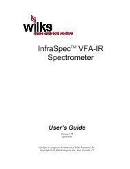
InfraCal ® TOG/TPHAnalyzerModel <strong>CVH</strong>User’s GuideInfraCal is a registered trademark of <strong>Wilks</strong> <strong>Enterprise</strong>, <strong>Inc</strong>.Copyright 2009 <strong>Wilks</strong> <strong>Enterprise</strong>, <strong>Inc</strong>., East Norwalk, CTwww.<strong>Wilks</strong>IR.comRev. 4.4, November 2009
Table of Contents1. InfraCal TOG/TPH Analyzer, Model <strong>CVH</strong> Overview ........................................................ 41.1. Introduction ................................................................................................................................41.2. Basic measurement concept .......................................................................................................41.3. Analyzer description...................................................................................................................41.3.1. Front operating panel ..........................................................................................................41.3.2. Back panel ...........................................................................................................................51.3.3. Description of the push button controls...............................................................................61.4. Analyzer Features .......................................................................................................................61.4.1. Internal Calibration: ............................................................................................................61.4.2. External Communication: ....................................................................................................61.4.3. Recall Function/Averaging Results .....................................................................................61.4.4. Printing the Result ...............................................................................................................62. Getting Started .................................................................................................................. 72.1. Installation ..................................................................................................................................72.1.1. Location ..............................................................................................................................72.1.2. Power Requirements ...........................................................................................................72.1.3. Warm up time ......................................................................................................................72.2. Zeroing the Analyzer ..................................................................................................................72.2.1. Setting the timer ..................................................................................................................82.2.2. Establishing Zero ................................................................................................................82.2.3. Zero Check ..........................................................................................................................83. Analyzer Calibration .......................................................................................................... 93.1. Data Presentation .......................................................................................................................93.2. Considerations for Calibration Standards ...................................................................................93.2.1. Calibration correlated to an Alternate Method ....................................................................93.3. Preparing Calibration Standards .................................................................................................93.3.1. Preparing Volumetric Standards .......................................................................................103.3.2. Preparing Gravimetric Standards ......................................................................................103.4. Calibrating in the Analyzer.......................................................................................................113.4.1. Selecting the Calibration Mode .........................................................................................123.4.2. Collecting calibration data ................................................................................................123.4.3. Entering the User Calibration Data with the Edit program................................................123.4.4. User Calibration Mode Procedure: ....................................................................................133.4.5. Calibration printing ...........................................................................................................134. Analyzing an Oil Sample ................................................................................................. 134.1. Analyzer Pre-Check .................................................................................................................134.2. 10 to 1 Extraction Procedure for Oil in Water .........................................................................134.2.1. Supplies Needed for Extraction in Water ..........................................................................134.2.2. Considerations: ..................................................................................................................144.2.3. Total Oil and Grease (TOG) Extraction from Water.........................................................144.2.4. Total Petroleum Hydrocarbon (TPH) Extraction from Water ...........................................154.3. 1 to 1 Extraction Procedure for Oil in Soil ...............................................................................154.3.1. Supplies Needed ................................................................................................................154.3.2. Total Oil and Grease (TOG) Extraction from Soil ............................................................154.3.3. Total Petroleum Hydrocarbon (TPH) Extraction from Soil ..............................................164.4. Dilution Procedures ..................................................................................................................164.4.1. 10:1 Dilution .....................................................................................................................164.5. Averaged Results Display ........................................................................................................162
5. Detailed Sample Stage Description ............................................................................... 175.1. Cuvette (<strong>CVH</strong>) sample stage ....................................................................................................175.1.1. Cuvette Sample Stage Description ....................................................................................175.1.2. Cuvette (Model <strong>CVH</strong>) Measurement Concept ..................................................................185.1.3. Cuvette Considerations .....................................................................................................186. Analyzer Specifications .................................................................................................. 196.1. External Power Requirements: .................................................................................................196.2. Physical: ...................................................................................................................................196.3. Environmental: .........................................................................................................................196.4. Electrical ..................................................................................................................................196.5. Calibration: ...............................................................................................................................207. Analyzer Communications Interface ............................................................................. 207.1. Abstract ....................................................................................................................................207.2. Physical Connection .................................................................................................................207.3. Communications port setup parameters ....................................................................................217.4. Operation ..................................................................................................................................217.5. Data Logging ............................................................................................................................217.6. Remote Zero Balance Control ..................................................................................................227.7. Remote Calibration Control .....................................................................................................228. Service and Customer Support ..................................................................................... 23Appendix A: Alternate Data Presentation ................................................................................ 24Appendix B-Correlation to an Alternate method ..................................................................... 25Appendix C: Solvent Options .................................................................................................... 26List of FiguresFigure 1 - The InfraCal TOG/TPH Analyzer: Front View of Analyzer .................................. 4Figure 2: The Display and Control Panel .................................................................................... 5Figure 3: The TOG/TPH Analyzer: Rear View .......................................................................... 5Figure 4: The TOG/TPH Analyzer Model <strong>CVH</strong> Sample Stage: Front View......................... 17Figure 5: The TOG/TPH Analyzer Model <strong>CVH</strong>: Top View.................................................... 17Figure 6: Measurement of IR Absorption with a Cuvette ....................................................... 183
_________________________________________________________________________1. InfraCal TOG/TPH Analyzer, Model <strong>CVH</strong> Overview1.1. IntroductionThe InfraCal TOG/TPH Analyzer, Model <strong>CVH</strong>, is designed to measure solvent extractable material(hydrocarbons or oil and grease) by infrared determination in water or wastewater. The InfraCal Model<strong>CVH</strong> InfraCal TOG/TPH Analyzer is designed for use with EPA Methods 413.2 and 418.1 that useFreon. With the discontinued use of Freon, other infrared transparent solvents, such as a hydrocarbonfreegrade of perchloroethylene, AK-225 or S-316 may be used in the extraction procedure.A dual detector is used in the TOG/TPH Analyzer to measure hydrocarbon concentrations at 3.4micrometers (2940cm -1 ) with a reference at 2.5 micrometers (4000cm -1 ).1.2. Basic measurement conceptThe InfraCal TOG/TPH Analyzer makes use of the fact that hydrocarbons such as oil and grease can beextracted from water or soil through the use of an appropriate solvent and extraction procedure. Theextracted hydrocarbons absorb infrared energy at a specific wavelength and the amount of energyabsorbed is proportional to the concentration of oil and grease in the solvent. The analyzer can becalibrated to read out directly in the desired units.1.3. Analyzer descriptionFigure 1: The InfraCal TOG/TPH Analyzer: Front View of Analyzer1.3.1. Front operating panelThe front panel consists of a 4 digit LED display and four labeled, touch-sensitive push button controlsas illustrated in Figure 2. The LED display remains illuminated while the analyzer is plugged in(switched on). When the instrument is on and not in use, the display may either show the result of the lastanalysis, or it may show idLE.4
1.3.2. Back panelFigure 2: The Display and Control PanelThe main power socket for the 12 Volt power supply is located on the back panel. The back panel alsoprovides a standard nine pin, female DB9 connector for serial (RS232-C) data communications with theanalyzer. This requires the use of a standard straight through serial data cable. See Section 8 for details ofdata communications with the InfraCal TOG/TPH Analyzer. The CAL lockout switch deactivates thefront panel CAL button to keep the internal calibration table from being inadvertently changed or turnedoff. For calibration, the switch is ON (I). After calibration the switch may be moved to the lockedposition (O). The back panel also contains the CE Mark designation indicating compliance with thecodes for operation within the European Community countries, and the analyzer serial number. Make apermanent note of the serial number, and provide this number when contacting <strong>Wilks</strong> <strong>Enterprise</strong> with aservice or warranty related issue.EN 61010-1EN 55022 Class BEN 50082-1+Serial #Made In U.S.A.Figure 3: The TOG/TPH Analyzer: Rear view5
1.3.3. Description of the push button controlsRUNRUN - initiates sample analysis (Section 4). Also used in CAL to record a calibrationsample (Section 3).RUNCALZERORECALLRECALLUP arrow control - used to increase numerical values used in the CAL function(Section 3).CAL – Hold for 2 seconds to select calibration type (uSEr, Edit or oFF). Also used togenerate a new user calibration. Quickly press and release to print the last result.ZERO - Hold for 2 seconds to zero balance the instrument (bAL appears on displayduring operation (Section 2). Also used to exit CAL. Quickly press and release to printthe current calibration table.RECALL - Quickly press and release to recall up to the last ten results (recall mode,section 4.5) or to display the average (averaging mode, section 4.5). Hold for 2 secondsto reset the printer sequence number.DOWN arrow control - used to decrease numerical values used in the CAL function(Section 3)1.4. Analyzer Features1.4.1. Internal Calibration:The InfraCal TOG/TPH Analyzer reads in relative absorbance units that are proportional toconcentration. An internal microprocessor allows the user to enter a calibration in order to read in thedesired units. The analyzer contains three different user selectable calibration modes. These are oFF,uSEr or Edit. Section 3 explains the calibration functions in detail.1.4.2. External Communication:The InfraCal TOG/TPH Analyzer supports communications to a PC, printer or controller via an RS-232Casynchronous serial communications port. This capability allows for collection of sample measurementdata and instrument control by a host computer. The RS-232 interface also allows for data transmissioninto an excel spreadsheet on a PC. It also allows for multiple calibration tables if more than one table isbeing used with a single instrument. Specification details for communication parameters are in Section 7.1.4.3. Recall Function/Averaging ResultsThe analyzer has the ability to store ten results for use with the averaging function or for local recall anddisplay (see Section 4.5).1.4.4. Printing the ResultAn optional printer can be connected to the analyzer through the RS-232C port located on the back. Toprint the result, momentarily press and release the CAL button. Note that the Cal Lock switch must be inthe (I) position. The result is printed on one line. The first number printed is a 5-digit sequence number.The sequence number is followed by the result. The remainder of the line contains the date, time and dayof the week. To reset the print sequence number, unplug the printer and plug it back in. The next resultwill print as sequence number 000001.6
____________________________________________________________________________2. Getting Started2.1. Installation2.1.1. LocationThe InfraCal TOG/TPH Analyzer may be installed virtually anywhere. It is not affected by vibration andit can operate over a broad range of ambient temperatures (40 o F, 4 o C to 110 o F, 45 o C).2.1.2. Power RequirementsThe analyzer is powered from a 12 volts d.c. power source. A standard 12 volt power supply is providedwith the analyzer, and this may be operated from any grounded a.c. outlet (line power requirements: 100 -250 VAC, 50-60 Hz, 0.5-0.3 amps). When operating, the TOG/TPH Analyzer consumes approximately 8watts (0.67 amps).For field use, the instrument may be connected to other sources of 12 volt d.c. power, such as an externalbattery pack or the cigarette lighter output of an automobile (contact <strong>Wilks</strong> <strong>Enterprise</strong> for details). If thelighter output is used, the vehicle engine should be switched off during operation of the analyzer. Usewith the engine running may result in the generation of a bAtt error code.Plug in the external 12 volt supply to the power connector at the rear of the instrument. When plugged in,the instrument display will show init for a short time. Once the power-on initialization is complete, theinstrument displays idLE. The TOG/TPH Analyzer is now ready for use.Note: the connector is polarized with the center pole positive. Failure to use the correct power supply orthe correct cable can result in permanent damage to the analyzer and may invalidate the warranty.The InfraCal internal memory, which retains the factory and user calibration tables could be erasedfrom a voltage spike or surge on the 120-220VAC line. The use of a surge protection device between theuser’s AC line and the 12V DC power supply is recommended to prevent the loss of calibration tables.2.1.3. Warm up timeFor normal operation, it is recommended that the instrument be allowed to warm up for 1 hour prior touse. However, the analyzer is sufficiently stable after 15 minutes, and meaningful measurements may beobtained at this time. If the analyzer is used under the 1 hour warm-up time, frequent checking of the zerois recommended for best results. The longer warm-up time is recommended prior to making criticalmeasurements and when performing analyzer calibration. The InfraCal TOG/TPH Analyzer draws verylittle power and, if used daily, it can be left on at all times (unless operated from an external batterypack).2.2. Zeroing the AnalyzerFor initial set-up, establish zero for the analyzer using the following procedure. The timer should be setprior to zeroing if using AK-223 solvent. Once a zero has been established, subsequent zero checksshould use the zero check procedure described in section 2.2.3.7
2.2.1. Setting the timerOverviewThe InfraCal TOG/TPH Analyzer contains a built in, user programmable, timer. Setting the timer to 5seconds will increase instrument stability and should definitely be done if AK-225 is the solvent used forextraction. A 10 second timer may be required for the AK-225.Timer ProgrammingThe CAL lockout switch must be in the on (I) position to set the timer (see figure 3, section 1.3.2). Pressand hold the RUN button until the current timer value is displayed. The value is displayed as 1 or 2 digitsin minutes and 2 digits in seconds, separated by a period (.). Release the RUN button once the currentvalue (initially 0.05) is displayed. Use the up-arrow and down-arrow keys to scroll the timer to thedesired value. Five seconds (0.05) is recommended. To zero the timer during programming, press theZERO button. Once the desired time has been programmed press the CAL button. The display will readidLE.Timer OperationThe timer is disabled when programmed to zero (0.00). When the timer is non-zero, it is invoked duringthe normal RUN, ZERO and CAL functions.Press and release RUN and the timer value is displayed. The timer will count down one second at a time.The dot separating minutes and seconds flashes to indicate the timer is counting. Once the timer reacheszero the display will read run during the sample measurement cycle. The result is displayed oncompletion.The ZERO function is initiated by pressing and holding the ZERO button until the timer value isdisplayed. The timer will count down as described above and bAL will then be displayed. On completionthe balance result is displayed. The timer is also invoked during calibration, each time the RUN button ispressed to analyze a sample.2.2.2. Establishing ZeroEnsure that the cuvette is clean. Clean the cuvette with solvent after each use.• Fill the cuvette with clean solvent the same as that used for extraction and place in the sample stage.• Press and hold the ZERO button until the display reads bAL. Release the button. A multiplier valueto 3 decimal places will be displayed when zero is established. The actual value is only of interestwhen reporting problems to the factory.• Press RUN. The display should read 00 + 02. If not, repeat the zero process.2.2.3. Zero CheckThe zero value is retained in permanent memory and is restored each time the instrument is powered up.It is recommended that the zero be checked and (if necessary) reestablished, on a daily basis.• To check the zero value, fill the cuvette with clean solvent and press the RUN button.• If the result is not + 02, reclean the sample holder and verify that the zero sample is notcontaminated.• Check zero again.• If the result is not + 02, reestablished the zero as described in 2.2.1_____________________________________________________8
3. Analyzer Calibration3.1. Data PresentationThe standard display format for the TOG/TPH Analyzer is absorbance (AbS). This is the format theanalyzer is preset for unless the customer specified otherwise. Other formats are available, and thesemay be set for specific applications. Details for other formats are in Appendix A – Alternate DataPresentation Modes.3.2. Considerations for Calibration StandardsThere are five choices for calibration.1. Prepare your own standards. Standard preparation is described in detail in section 3.3.2. Purchase pre-prepared standards from <strong>Wilks</strong> <strong>Enterprise</strong>.3. Calibrate to an alternate laboratory method.4. Non-certified factory calibration. <strong>Wilks</strong> <strong>Enterprise</strong> can provide the InfraCal TOG/TPHAnalyzer with a non-certified 5-point factory calibration using either Freon or Hexane calibrationstandards5. Certified laboratory calibration. <strong>Wilks</strong> <strong>Enterprise</strong> can recommend a certified laboratory foranalyzer calibration.3.2.1. Calibration correlated to an Alternate MethodEach type of oil and grease analysis sees different physical properties and will sometimes give differentresults from each other. The InfraCal TOG/TPH Analyzer can be calibrated against an alternate methodrather than with prepared standards. For calibration against an alternate method obtain duplicate samplesor if possible, test the same sample with the InfraCal and the alternate method. Data collected for thispurpose should be obtained with the calibration in the oFF mode (section 3.4.1). With a minimum of 10data points, make a graph with InfraCal absorbance data vs. the alternate method values. Select 3 to 5data points within the desired measurement range of operation and enter these calibration points into theInfraCal memory using the Edit program that is described in section 3.4.3.Note: If data was collected with the calibration from standards programmed into the Edit program withthe edit program on, refer to Appendix B for the calculations needed to correlate the alternate methodvalues to the calibrated InfraCal TOG/TPH values for new values to enter into the Edit program.3.3. Preparing Calibration StandardsStandards can be made gravimetrically (mg/L for water, mg/kg for soil) or volumetrically (ppm).Customers can prepare their own standards using a non-volatile (heavy weight) oil such as “3-in-1” or anactual oil sample. Calibration standards should cover the desired range for the analysis. An idealcalibration set contains three to five samples. A maximum of 20 samples can be used.The calibration curve for oil and grease is typically linear up to 3000 ppm (300 ppm for oil in water witha 10:1 extraction ratio). Above 4000 ppm (or 400 ppm for oil in water samples) the curve flattens out.Because the InfraCal TOG/TPH Analyzer performs a point-to-point calibration, samples above the linearrange will be accurate up to the highest calibration standard. It is best to calibrate to 4000 ppm (400ppm9
for 10:1 extraction ratios) and dilute the extract for samples above this range. See section 4.4 for dilutionprocedures. The lowest concentration standard should measure at least 10 on the InfraCal in the oFFmode for calibration. All successive samples should be spaced apart by at least 10 absorption units.3.3.1. Preparing Volumetric StandardsSupplies needed for volumetric calibration125-ml Teflon wash bottle10-ml graduated cylinder40-ml vials with Teflon lined caps (at least 3 for holding standards)100 microliter syringeSolvent (see Appendix C)Calibration oilBelow is a chart for mixing volumetric standards. For water analysis with an extraction ratio of 10:1, theoil and grease is concentrated 10 times in the solvent. The actual value of the standard is divided by 10in order to match the concentrated value of the extract. The water analysis column below makes thiscorrection. For standards below 1000 ppm (100 ppm for water samples), it is best to mix a concentratedstock solution to be diluted for lower standards.For example, the desired range for a particular analysis is typically 10 ppm with values up to 100 ppm inwater.1. Prepare a stock solution for 100 ppm for water analysis. (10 ul oil in 10 ml of solvent).2. Pour half (5 ml) into a 10-ml graduated cylinder.3. Fill with solvent up to 10 ml. This will cut the 100 ppm standard in half to be 50 ppm.4. Repeat this again with the 50 ppm standard for a 25 ppm standard.This makes three standards (100 ppm, 50 ppm and 25 ppm) within the operating range of 10 – 100 ppm.Actual ppm Corrected ppm for Oil Solvent(1:1) Extraction 10:1 extraction ratio(soil analysis) (water analysis)4000 400 40ul 10 ml3000 300 30ul 10 ml2000 200 20ul 10 ml1000 100 10 ul 10 mlNote: To convert ppm to mg/l, multiply by the specific gravity of the oil used for the calibration standard(for 3-in-1 Oil or 30W motor oil, use 0.865.) by the ppm value to get a mg/l value3.3.2. Preparing Gravimetric StandardsSupplies needed for gravimetric calibration125-ml Teflon wash bottle10-ml graduated cylinder10-ml volumetric10
40-ml vials with Teflon lined caps (at least 3 for holding standards)Solvent (see Appendix C)Calibration oilAnalytical Balance that reads to .001 gramPrepare a stock solution and make the appropriate dilutions to cover analysis range. For water analysiswith an extraction ratio of 10:1, the oil and grease is concentrated 10 times in the solvent. The actualvalue of the standard is divided by 10 in order to match the concentrated value of the extract.1. Weigh about 0.1 gram of oil in a 10-ml volumetric flask.2. Record the exact weight.3. Fill with solvent up to the 10 ml line.Calculate the exact concentrations as shown below:Oil weight x 10,000 = mg/l (multiply grams x 1000 to equal mg anddivide 10 ml by 100 to equal liters = 0.1. 1000 divided by 0.1 = 10,000)For an oil weight of 0.110 gram in 10 ml, the Stock solution will be:0.110g x 10,000 = 1,100 mg/lUsing the above hypothetical stock solution, an example of dilutions for the desired range for a particularanalysis that is typically 10 mg/l with values up to 100 mg/l in water could be as follows.Stock solution 1,100 mg/l divided by 10 (for a 10:1 extraction in water) = 110 mg/l1. Pour half of the stock solution(5 ml) into a 10 ml graduated cylinder.2. Fill with solvent up to 10 ml. This will cut the 110 mg/l standard in half to be 55 mg/l.3. Repeat this again with the 55 mg/l standard for a 27.5 mg/l standard.This makes three standards (110 mg/l, 55 mg/l and 27.5 mg/l) covering the operating range of 10 – 100mg/l for oil in water analysis.3.4. Calibrating in the AnalyzerThe Analyzer contains three different user modes in the calibration. These are uSEr, Edit or oFF. If afactory calibration is installed there will be a fourth mode, FACt.In the oFF mode the instrument measures levels in arbitrary absorption units that are proportional toconcentration levels. Higher values indicate increased levels of hydrocarbons. This mode should be usedto collect “raw” data for the Edit mode or for comparing to an alternate method.The Edit mode allows the user to edit an existing calibration table or to create one from scratch, usingabsorption values obtained in the oFF mode. This is the recommended calibration mode as standards (orsamples used to calibrate to an alternate laboratory method) may be run several times and an average canbe entered into the table.The uSEr mode enters the calibration at the time the standards are presented to the analyzer.11
3.4.1. Selecting the Calibration Mode• Press the CAL button for two seconds, until CAL appears on the display. Press the RECALL buttonto display the active table, one of uSEr, Edit or oFF. Press and release the RECALL buttonrepeatedly until the desired mode is displayed.• Press the ZERO button to exit the calibration mode. iDLE will be displayed.3.4.2. Collecting calibration dataCalibration data can be collected from standards (section 3.3) or from actual samples compared to analternate oil and grease measurement method (section 3.2.2). If the data is to come from actual samples,skip to section 4 for extraction procedures.1. Allow the analyzer to warm up at least one hour.2. Always zero the Analyzer prior to calibration or collecting data for calibration analysis (seesection 2.2).3. Make sure the calibration is in the oFF mode (section 3.4.1).4. Fill cuvette with the lowest value standard, insert in sample stage and press run. Record theresult on the table below (AO1). Record the standard value in CO1. Standards may be runseveral times and an average can be entered on the table below.5. Repeat for the remaining standards.Note: The results can plotted graphically as a calibration curve. The resulting plot can be used toprepare a reference chart for users who prefer not to use the analyzer’s internal calibration or for datapoints to be edited into calibration.Absorbance Versus Calibration Standard or Alternate Method Table(Absorbance Value)(Calibration Standard in Desired Units)A01 = C01=A02 = C02 =A03 = C03 =A04 = C04 =A05 = C05 =↓↓A20 = C20 =N (Number of calibration points or calibration standards) = _______________3.4.3. Entering the User Calibration Data with the Edit program1. Press the CAL button for two seconds, until CAL appears on the display. Press RECALL untilEdit is displayed.2. Press CAL, the display will read n= for a short time, followed by the number of entries currentlyin the calibration table. Scroll to the desired number of entries (0 - 20). Selecting 0 will erase anyexisting calibration table.3. Press CAL to proceed. The display will read A01= for a short time followed by the currentabsorption value for the first calibration table entry. Scroll this to the desired value from the“absorbance versus calibration standard” table, using the up/down arrows.4. Press CAL again and the display will read C01= followed by the current analyzer concentrationvalue for the entry. Scroll this to the desired value from the table. Continue to press CAL to step12
through all absorption and concentration values for the table size (n=) entered. Once all entries havebeen created the display will read idLE.3.4.4. User Calibration Mode Procedure:Note that this is not the preferred method to use for calibration of the InfraCal Analyzer. If youwould like to use this method, please contact tech@wilksir.com for instructions.3.4.5. Calibration printingWith the optional printer, the current calibration table can be printed by momentarily pressing andreleasing the ZERO button when the analyzer is idle. The first line indicates which calibration is activefollowed by the date and time. The second line gives the headings for the calibration table that follows.ABS represents absorption and CON represents concentration. The table headings are followed by thebalance value. One additional line is printed for each calibration table entry. The absorption andconcentration values are given._____________________________________________________________________________4. Analyzing an Oil SampleThese extraction procedures are a simplified version of ASTM Method D 3921 and EPA methods 418.1or 413.2. The ASTM or EPA extraction methods may be used if desired.4.1. Analyzer Pre-Check1. For calibration, allow the analyzer to warm-up and stabilize for one hour2. Ensure that the cuvette is clean. Use clean solvent to rinse the cuvette after each use. Do not usewater to clean the cuvette.3. Perform a zero check (section 2.2.3)4. Make sure glassware and sample containers are clean.4.2. 10 to 1 Extraction Procedure for Oil in Water4.2.1. Supplies Needed for Extraction in Water125-ml Teflon wash bottle100-ml graduated cylinder with stopper or sample bottle graduated in ml (i.e: 177-ml prescriptionbottles)125-ml stopper separatory funnel or sample bottles with septa capsHydrochloric (HCl) or sulfuric acid (H 2 SO 4 )(dilute with water 1:1)pH indicator strips or pH meter10-ml or 25-ml Graduated cylinder (depending on sample size)Sodium sulfate (Na 2 SO 4 ), ACS, granular anhydrous13
Glass funnelWhatman 40 filter paper, 11cm, or equivalentSilica gel (for TPH), anhydrous, 75-150 micrometersDisposable polyethylene pipette or equivalent5-mL syringe (for use with prescription bottles)Solvent (see Appendix C for solvent options)Note: With a 50 mm Cylindrical Cell (Model <strong>CVH</strong>-50), a larger extract volume is needed to fill the cell.A minimum of 200-mL of sample and 20-mL of solvent is needed. The glassware sizes listed above willneed to be adjusted for the larger volume sample.4.2.2. Considerations:• Make sure glassware for used for analysis is clean. Any residual hydrocarbons in the glassware andsampling containers will be extracted and added to the TOG or TPH reading. To check theglassware, rinse with solvent then put the solvent rinse in the quartz cuvette. A reading above 04shows contaminated glassware.• Oil and grease tends to adhere to the surfaces it comes in contact with. Use the entire samplecollected. Either mix the solvent and sample in the sample collection container or rinse the samplecollection container with a portion of the solvent to be used for extraction.4.2.3. Total Oil and Grease (TOG) Extraction from Water1. Pour measured sample into separatory funnel. If using a graduated prescription bottle with asepta cap, solvent can be mixed directly in the bottle without using the separatory funnel.2. Adjust the pH to less than 2 with Hydrochloric acid or Sulfuric Acid (typically 3-5 dropsdepending on buffers in sample).3. Add one tenth of the sample size of solvent to the sample collection container to rinse interiorsurfaces and cap. (With the 177-ml prescription bottle, it is convenient to collect 140 ml ofsample and add 14 ml of solvent). Pour this solvent into separatory funnel containing sample ordirectly into the prescription bottle.4. Shake the separatory funnel or prescription bottle vigorously for 2 minutes with periodic ventingto release excess pressure.5. Allow the phases to separate.6. Place a filter paper in a filter funnel and add approximately 1 gram (1Tablespoon) of sodiumsulfate.7. Drain the solvent (lower) layer from the separatory funnel through the sodium sulfate into a cleancontainer (10-mL graduated cylinder can be used). With the prescription bottle, invert the bottleso that the solvent layer fills the neck. Using a 5 ml syringe withdraw 4-5_mL of the solventlayer and deliver through the sodium sulfate into a clean container.Note: Use of the sodium sulfate is necessary to prevent water from interfering with the analysis. Withtotally hydrophobic solvents, this step may be skipped. It is not necessary to collect all of the solvent butit is necessary to preclude water to prevent caking of the sodium sulfate.8. Fill the cuvette with the extract.9. Place the cuvette into the holder on the InfraCal TOG/TPH Analyzer with the frosted side facingfront.10. Press the RUN button and the value will be displayed.11. If the result is above the calibration range, see section 4.4 for dilution procedure.14
4.2.4. Total Petroleum Hydrocarbon (TPH) Extraction from WaterThe difference between TPH (Total Petroleum Hydrocarbon) and TOG (Total Oil and Grease) is thepolar organics are removed from the extract using silica gel. The remaining hydrocarbons are the nonpolarcomponents considered to be TPH.1. Follow the above procedure steps 1-7.2. Place a filter paper in a filter funnel and add approximately 1 gram (1 Tablespoon) of silica gel.3. Pour extract from container though the silica gel into a clean container.4. Fill the cuvette with the extract.5. Place the cuvette into the holder with the frosted side facing front.6. Press the RUN button and the value will be displayed.7. If the result is above the calibration range, see section 4.4 for dilution procedure.4.3. 1 to 1 Extraction Procedure for Oil in Soil4.3.1. Supplies Needed40-mL vials with Teflon-faced caps (EPA/VOA)10-mL or 25-mL Graduated cylinder (depending on sample size)Sodium sulfate (Na 2 SO 4 ), ACS, granular anhydrousGlass funnel (for TPH)Whatman 40 filter paper, 11cm, or equivalent (for TPH)Silica gel (for TPH), anhydrous, 75-150 micrometersDisposable polyethylene disposable pipette or equivalentPlastic air syringe with filter frit and plunger (or equivalent)Sample spatulaSolvent (see Appendix C for solvent options)Analytical balance that reads to .1 gram4.3.2. Total Oil and Grease (TOG) Extraction from Soil1. Collect a soil sample directly in a washed and weighed (to the nearest 0.1 gram) EPA/VOA 40ml vial. The sample should be about ¾ of the volume of the vial.2. Weigh the sample to the nearest 0.1gram, subtracting the tare weight of the vial. Note the weight.3. If the sample is wet and clumpy, add up to 5 grams of sodium sulfate. Use the spatula to breakup the clumps.4. Add the same amount of solvent in ml as the soil sample weight in grams (do not include theweight of the sodium sulfate). ie: for 11.2 grams of soil, add 11.2 ml of solvent. This will give a1:1 extraction ratio.5. Cap the vial with the Teflon side of the liner toward the sample. Shake vigorously for 2 minutes.15
6. Pour the solvent into the plastic air syringe with filter frit, leaving as much of the soil in the vialas possible.7. Place the plunger into the air syringe force the solvent through the filter frit into a clean containeror directly into the cuvette.8. Place the cuvette into the holder with the frosted side facing front.9. Press the RUN button and the value will be displayed.10. If the result is above the calibration range, see section 4.4 for dilution procedure.4.3.3. Total Petroleum Hydrocarbon (TPH) Extraction from SoilThe difference between TPH (Total Petroleum Hydrocarbon) and TOG (Total Oil and Grease) is thepolar organics are removed from the extract using silica gel. The remaining hydrocarbons are the nonpolarcomponents considered to be TPH.1. Follow the above procedure steps 1-7.2. Place a filter paper in a filter funnel and add approximately 1 teaspoon of silica gel.3. Pour extract from container though the silica gel into a clean container.4. Fill the cuvette with the extract.5. Place the cuvette into the holder with the frosted side facing front.6. Press the RUN button and the value will be displayed.7. If the result is above the calibration range, see section 4.4 for dilution procedure.4.4. Dilution ProceduresIf the sample reading is above the highest calibration point, a dilution must be performed to bring it intothe measurement range.4.4.1. 10:1 Dilution1. Pour 1 ml of solvent extract into a 10-mL graduated cylinder2. Add 9 mL of solvent for a 10 to 1 dilution.3. Mix and pour diluted extract into a clean cuvette.4. Add a zero to the result on the InfraCal’s digital display and record your reading, i.e. if the resultis 465, the extract value after dilution is 4650 ppm.5. This procedure may be repeated if the extract is still not within the calibration range. Add twozero’s to the InfraCal’s digital display if two dilutions are performed.4.5. Averaged Results DisplayThe InfraCal Analyzer can display the average of up to ten sample measurements. To use the averagingmode, use the following procedure:• Momentarily press the RECALL button once and ignore the result displayed.• Analyze up to ten replicate samples using the measurement procedure described above.• Momentarily press the RECALL button to display the average.The next sample measurement will then start a new average accumulation.The Analyzer alternatively can be configured to recall the last 10 measurements (from newest to oldest)in a circular fashion. First the TOG/TPH Analyzer must be switched from the average mode (factory16
default) to the recall mode as described below. Once the recall mode is selected momentarily press theRECALL button repeatedly to display the previous results. The TOG/TPH Analyzer recall mode can beswitched by pressing the ZERO button first, immediately followed by the RECALL button and holdingboth buttons for two seconds. The display will read rCL when switched to the recall mode. Repeat theprocedure to return to average mode. The display will read Ag._________________________________________________________________________5. Detailed Sample Stage Description5.1. Cuvette (<strong>CVH</strong>) sample stage5.1.1. Cuvette Sample Stage DescriptionThe InfraCal TOG/TPH Analyzer Model <strong>CVH</strong> is supplied with an integrated 10mm cuvette holder andoptics sensing system. The sample stage includes the infrared source (modulated) and detector system,positioned such that an elliptical energy beam is transmitted through the sample and focused directly onthe detector-sensing window.DetectorLocationSourceLocation#8-32 x 11/32” Long Ball PlungerUse small flat screwdriver foradjustment of pressure snapsFigure 4: The InfraCal TOG/TPH Analyzer, Model <strong>CVH</strong> Sample Stage: Front ViewFigure 5: The InfraCal TOG/TPH Analyzer, Model <strong>CVH</strong>: Top View17
5.1.2. Cuvette (Model <strong>CVH</strong>) Measurement ConceptThe InfraCal Model <strong>CVH</strong> Analyzer makes use of the fact that hydrocarbons such as oil and grease can beextracted from water or soil through the use of an appropriate solvent. The extracted hydrocarbonsabsorb infrared energy at specific wavelengths and the amount of energy absorbed is proportional to theconcentration of the oil/grease in the solvent. This can be directly calibrated or converted to the amountof oil in the original sample if the ratio of solvent to water is carefully controlled.Model <strong>CVH</strong> is designed for use with EPA Methods 413.2 and 418.1. In this case, freon is the solventused. Since freon is transparent at the analytical wavelength used for hydrocarbon absorption, themixture is placed directly in a quartz cuvette with a known path length. When the cuvette is placed in thesample stage a focused beam is passed through the sample and focused directly on the dual detectorpackage. The energy collected at the analytical wavelength (I A ), is reduced when compared to the energycollected at the reference wavelength (I R ). The oil concentration is determined by a calculation of thelogarithm of the ratio of the light transmission at the reference wavelength to the light transmission at theanalytical wavelength (Beer-Lambert law) as shown in Figure 6. The Beer-Lambert law assumes a linearrelationship between absorbance and concentration. Deviations from linearity are determined byobtaining absorbance values from known samples and an internal point-to-point calibration table isprepared (Section 3) so that actual concentration is directly presented on the display. If the concentrationratio used during extraction (typically 10 parts sample to 1 part solvent for liquid samples and 1:1 for soilsamples) is taken into account during calibration, the display will read directly in the desired units.SampleSourceFilters (I R / I A )DetectorsA = log I R / I A5.1.3. Cuvette ConsiderationsFigure 6: The Measurement of IR Absorption ofan Oil Sample with a Cuvette1. All cuvettes must be made with infrared transmitting quartz windows (“Infracil” or equal).2. Insert the cuvette in the holder with the frosted sides facing the front and back of the Analyzer.For optimum performance always insert with the same orientation. If multiple cuvettes are usedthey should be matched.3. The cuvette holder accepts standard 10-mm quartz cuvettes. For oil and grease determinationsbased on EPA Methods 413.2 and 418.1, the range in mg/l is from less than 2 to 4000 mg/l. Forconcentrations consistently above 4000 mg/l, 2 mm or 1 mm cuvettes may be used. These will fitin the Model <strong>CVH</strong> sample stage with appropriate adapters.4. Variation in cuvette size may require sample system readjustment. If the test cuvette series iseither too tight or too loose for proper insertion and performance, the pressure snaps inside thesample holder will need minor adjustment. To remove the sample system slide the stage to theleft and then lift the right edge.Note: The cables do not have to be removed. With a slotted head screwdriver, turn the two (2) pressuresnaps (clockwise tightens; counter clockwise loosens) 1/4 turn (see figure 4). Re-insert cuvette and“feel” for proper tightness. Reinstall sample system when proper pressure snap tightness has beenachieved for your cuvettes.18
_____________________________________________________________________________________6. Analyzer Specifications6.1. External Power Requirements:The InfraCal TOG/TPH Analyzer operates off external 12-volt power. The power sources can be eitherregulated DC power supplies or an external battery. This power can be provided by the user or by <strong>Wilks</strong><strong>Enterprise</strong>, <strong>Inc</strong>. The suggested minimum requirement specifications for the 12 volt power source appliedto the analyzer are described below:Wall Supply Specifications:Input: 100-250 VAC, 50-60 Hz, 0.5AOutput: 12 VDC, ±1%, 25 WattsBattery Supply Specifications:Output: 14 VDC Maximum, 11 VDC MinimumLoad Specifications:1.5 Amperes Peak6.2. Physical:Dimensions: 6.5 in. x 6.5 in. x 5 in. (165 mm x 165 mm x 127 mm)Weight: 4.5 lb. (2.0 kg.)Control: Display (output) 4 digit 7 segment red LED,5/8 in. character heightUser (input)4 multi-function push-button switchesConnectors: Power -- Switchcraft Model 760 plug or equivalentCommunications -- 9-pin D-Sub, female6.3. Environmental:Temperature: Non-operating -- 0°F (-18°C) to 125°F (52°C)Operating -- 40°F (4°C) to 110°F (45°C)Humidity: Relative -- 10% to 60% non-condensing6.4. ElectricalNoise: Rejection -- 60 dB minimumDrift:Short term Ambient --(< 1 Hr.) ± 0.3% of full scaleLong term Ambient -- (> 1 Hr.) ± 0.1% of full scaleTemperature -- ± 0.03% of full scale per degree CRepeatability -- ± 0.1% of full scaleResponse: On Delay -- 5, 10, 15 or 20 second factory-set intervalsMeasure Time -- 5 secondsModes -- Local control or remote PC control19
Resolution: Conversion -- 16 Bits (0.0015%)Ranging: Digital Ranging -- 256 step automatic rangingAnalog Range -- 0 to 4.096 voltsAnswer Range -- Absolute; 00 to 9999Percent; 0.0 to 100.0%Decimal; .00 to 99.99Measure Range -- Dependant on sample concentration ratioMeasurement Accuracy:± 1% of full scaleMeasurement Repeatability: ± 0.1%, ±1 digitMemory: Non-volatile memory for calibration and configuration data6.5. Calibration:• Electronic zero balance adjustment• Up to 20 point curve fitting calibration• Modes: Edit TableOffFactory (special order)7. Analyzer Communications Interface7.1. AbstractThe InfraCal TOG/TPH Analyzer supports communications to a PC or other host via an RS-232Casynchronous serial communications port. This capability allows for collection of sample measurementdata and instrument control by a host computer. The host can also maintain calibration tables anddownload them to the instrument as required. This is particularly useful when more than one table isbeing used with a single instrument. Specification details for interfacing user customized hostsoftware are as follows:7.2. Physical ConnectionThe InfraCal TOG/TPH Analyzer is connected to the external device via the 9-pin female DB9 connectorlocated on the rear panel in the lower left-hand corner. The InfraCal TOG/TPH Analyzer operates as aDCE device. To connect to a PC, a standard straight through 9 pin cable can be used, but only 3 wires arerequired. 1 The required signals are Transmit Data (TXD), Receive Data (RXD) and Ground (GND). Thepin out is as follows:Function PinRXD 3TXD 2GND 51 Systems with serial numbers lower than 10200 require a null modem cable or null modem adapter.20
7.3. Communications port setup parametersThe port setup required by the InfraCal TOG/TPH Analyzer is:• 9600 baud• 8 data bits, 1 stop bit• No parity7.4. OperationThe TOG/TPH Analyzer accepts ASCII commands from the host and returns data as a response to certaincommands or, in data logging mode, on completion of a measurement cycle. All commands are twocharacters in length. Certain commands have parameters that follow the command. Parameters areseparated by commas. All commands are terminated by a carriage return character. All data responses arecomma separated ASCII fields, terminated by a carriage return character. The first field indicates theresult type; the remaining fields are the result. Result types are ‘B’ for balance results, ‘R’ for run resultsor ‘C’ for calibration data. The result format is determined by the presentation mode and is identical tothe LED display data. The Read Display Mode command returns a two character mode code. Alphabeticcharacters can be sent in upper or lower case. Response data is always upper case.Command SetCommand Description Response ExamplesRB Read balance B,1.025 B,0.865RR Read displayed result R,27.5 R,315 R,1.873RU Run (same as RUN button) NoneRA Run & display uncalibrated result NoneBABalance (same as Zero switch) NoneLR Enable results data logging NoneDR Disable results data logging NoneRM Read display mode MA, MP, MD or MRMA Set display mode to absolute NoneMP Set display mode to percent NoneMD Set display mode to decimal NoneMR Set display mode to ratio NoneWB, Set balance dataNoneRC, Read calibration table See detailed descriptionWC, Set calibration tableNoneCM Read Calibration Mode CD, CE or CFCD Disable Calibration NoneCE Enable User Calibration NoneCF Enable Factory Calibration NoneES Return error status E,0 E,2RE System reset NoneID Return firmware ID 2.02.067.5. Data Logging21
Data logging provides results output at the end of each RUN or BALANCE cycle. The results areoutput when data logging is enabled both for functions initiated from the instrument control paneland functions initiated by the host. The format of the data returned after a RUN cycle is as shown forthe RR command and is determined by the display mode. The format of the data returned after aBALANCE cycle is as shown for the RB command. The RA command allows the host to initiate arun cycle and data log a result that is not adjusted by the calibration procedure. This can be used byan intelligent host resident calibration table generator.7.6. Remote Zero Balance ControlThe instrument zero balance can be controlled via the communications port. The RB, WB and BAcommands provide the necessary controls. This feature can be used to store multiple zero values fordifferent operating conditions. This feature combined with the calibration controls described in thenext section can be used to maintain multiple calibration curves when using the instrument formultiple applications.The RB command will retrieve the current zero balance data. The WB command can then be used toreset the current zero balance to a previously recorded value. The WB data field is identical in formatto the data returned in response to the RB command.The BA command can be used to initiate a zero balance function under remote control. The operationis identical to initiating a zero balance from the instrument control panel. The user must insert thezero sample in the instrument prior to issuing this command. If data logging is enabled the result willbe returned on completion of the function. The data format is identical to the RB command response.The result can optionally be read with the RB command if data logging mode is not used.7.7. Remote Calibration ControlCalibration data can be retrieved or set under remote control. Due to the complexity of the calibrationfunction (and the need to utilize multiple calibration standards) initial calibration can only beperformed from the instrument panel. Another approach is to use the host to generate one or morecalibration curves from uncorrected data log results collected with the RA command. This techniqueis extremely useful if the user desires to generate a calibration curve based on an average result ofseveral measurements from a lot of each calibration standard.The RC command is used to retrieve the current calibration table. A Calibration table consists of zeroto twenty entries. The RC command can take the following forms:RCRC,0RC,nRead entire calibration tableRead calibration table sizeRead a single calibration table entry, where n is the entry number.The RC,0 command response is C,n where n is the number of calibration table entries from 0 to 20. If0, the instrument is not calibrated. Otherwise, n is the number of calibration table entries.The RC,n command response is C,n,x,y where n is the entry number as received, x is the rawmeasurement data as it appears on the display during calibration and y is the actual value as set bythe user during calibration. The format is determined by the display mode (absolute, percent, ordecimal). Calibration commands should not be used when in ratio mode since ratio mode does notuse a calibration table. An RC command requesting data for a table entry number greater than thecurrent table size returns erroneous data.22
The RC command with no arguments returns the complete calibration table, one entry at a timestarting with the table size information. The individual entries are then returned in numerical orderup to the number of entries.Read Calibration Table ExampleAssume the instrument is calibrated in the absolute mode using three standards. Assume thecalibration results were as follows:The RC command will return the following:C,0,3C,1,15,30C,2,26,50C,3,33,70The RC,0 command will return C,0,3The RC,2 command will return C,2,26,50Entry Measured Actual1 15 302 26 503 33 70The WC command can be used to download calibration table data based on previously uploaded dataor as determined by a host program. The command format is WC,n,x,y where the parameters areidentical in format to the RC command. The parameters must match the current display mode. Whenusing the WC command the table size and all necessary table entries should always be downloaded.Once all table entries have been downloaded the table size should be set.Write Calibration Table ExampleTo download the calibration table described in the previous example, send the following commands:WC,1, 15,30WC,2, 26,50WC,3, 33,70WC,0,38. Service and Customer SupportYour InfraCal ® TOG/TPH Analyzer may have been purchased either directly from <strong>Wilks</strong> <strong>Enterprise</strong> orfrom a local dealer or representative. If you have a technical question relative to the operation of theinstrument or relative to the analysis, please contact <strong>Wilks</strong> <strong>Enterprise</strong> at the contact address providedbelow:Customer Services Department<strong>Wilks</strong> <strong>Enterprise</strong>, <strong>Inc</strong>.25 Van Zant Street, Suite 8FEast Norwalk, CT 06855USA23
Telephone: (203) 855-9136FAX: (203) 838-9868E-mail: tech@<strong>Wilks</strong>IR.comService and RepairDuring the warranty period, <strong>Wilks</strong> <strong>Enterprise</strong>, <strong>Inc</strong>. offers free factory service for all failures that occurfrom normal instrument usage. The user is only required to cover the cost of shipping the instrument tothe factory. After the warranty period, the user is required to cover the factory’s cost of servicing plus allshipping charges. Normal one week turnaround is offered for all InfraCal instruments that are returned tothe factory for service. For users requiring faster service times, <strong>Wilks</strong> <strong>Enterprise</strong> also offers an advancereplacement program that can respond to a user’s needs with instrument replacement typically in lessthan 24 hours. For extended service contracts, advanced replacement programs, factory service chargesor sample system installation procedures, please contact <strong>Wilks</strong> <strong>Enterprise</strong>, <strong>Inc</strong>. for details.Appendix A: Alternate Data PresentationThe standard display format for the TOG/TPH Analyzer is absorbance (AbS) It provides relativeabsorbance value. Other formats are available, and these may be set for specific applications.Note: The TOG/TPH Analyzer must be calibrated in the selected data presentation mode. Changing thedata presentation mode requires re-calibration.The following are the different data presentation modes available of the InfraCal analyzer:The following are the different data presentation modes available of the InfraCal analyzer:Percent Mode (PCt): Calculated values are displayed to a single decimal place (0.0).Decimal Mode (dEC): Calculated values are displayed to two decimal places (.00)Absorption Mode (AbS): An arbitrary scale related to the raw absorption of the sample (00).Note: Inserting a decimal point does not change the raw absorbance value displayed for a given sample.ie: an Abs reading of 25 becomes 2.5 (pct) or .25 (dec).Note: Inserting a decimal point does not change the raw absorbance value displayed for a given sample.ie: an Abs reading of 25 becomes 2.5 (dec) or .25 (pct)Ratio Mode (RAt): A threshold based scale where a value defining an acceptable limit for maximum orminimum acceptable concentration is set to the value of 1.000. All values less than 1.000 indicate that theconcentration is less than the threshold, while all values greater than 1.000 indicate that the concentrationis greater than the threshold.The TOG/TPH Analyzer display format can be switched between modes by pressing and holding boththe CAL and ZERO buttons for two seconds. Each time the CAL and ZERO buttons are pressed thedisplay mode changes. Release both buttons and repeat until the desired mode is displayed. The displaywill read: AbS for absorption mode, PCt for percent mode, dEC for decimal mode, and RAt for ratiomode. Push RUN to exit the display mode.24
Appendix B: Correlation to an Alternate MethodIf values for sample analysis were taken with the Edit program on and calibration data in the Editprogram, The following can be used to calculate revised calibration points to re-enter into the Editprogram.Rule Of Thumb:• If the laboratory’s analysis is greater in concentration than the Field analyzer’s analysis, use amultiplier with the field instrument.• If the laboratory’s analysis is less in concentration than the Field analyzer’s analysis, use adivider with the field instrument.Example 1:Assume the sample analysis on the <strong>Wilks</strong> InfraCal read as follows:SAMPLE A = 25 ppmSAMPLE B = 13 ppmSAMPLE C = 11 ppmAssume the alternate method to analyze the duplicate samples read as follows:SAMPLE A= 63 ppmSAMPLE B= 33 ppmSAMPLE C= 28 ppmIn this case the alternate method read higher Oil and Grease concentrations than the <strong>Wilks</strong> InfraCalAnalyzer. Therefore the difference must be determined by dividing the lowest number into the highestnumber. The instrument must be made to read higher. A multiplier must be determined as shown inthe example below.InfraCal results:25 + 13 + 11 = 49 ppmAlternate Method Results63 + 33 + 28 = 124 ppm124 divided by 49 = 2.5 multiplierThe multiplier for this example is 2.5. Therefore multiply the value from the “Calibration Standard inDesired Units”(CO1, CO2…) column in the Absorbance Versus Calibration Standard or AlternateMethod Table (section 3.4.2) by 2.5. This will correlate the values to an alternate method. The newCalibration Standard values can be re-entered into Edit program (see section 3.4.3).Example 2:Assume the sample analysis on the <strong>Wilks</strong> InfraCal read as follows:SAMPLE A = 63 ppmSAMPLE B = 33 ppmSAMPLE C = 28 ppmAssume the analysis using the alternate method to analyze the duplicate samples read as follows:SAMPLE A= 25 ppmSAMPLE B= 13 ppmSAMPLE C= 11 ppm25
In this case alternate method read higher Oil and Grease concentrations than the <strong>Wilks</strong> InfraCalAnalyzer. Therefore the difference must be determined by dividing the lowest number into the highestnumber. The instrument must be made to read lower. A divider is needed instead of a multiplyer.As in example 1 divide the lowest number into the highest number to get thecorrelation factor.124 divided 49 = 2.5 dividerThe divider for this example is 2.5. Therefore divide the value from the “Calibration Standard in DesiredUnits”(CO1, CO2…) column in the Absorbance Versus Calibration Standard or Alternate Method Table(section 3.4.2) by 2.5. This will correlate the values to an alternate method. The new CalibrationStandard values can be re-entered into Edit program (see section 3.4.3)._____________________________________________________________________________Appendix C: Solvent Selection GuideFreon-113 A volatile CFC compound previously specified for EPAMethods 413.2 and 418.1. While its manufacture has been discontinued, its use has been extended by theEPA until 2003 and it is readily available in many parts of the world. Since it is heavier than water, thesolvent after extraction will be on the bottom. Because of its infrared transparency, it can be used with a10mm cuvette or 50mm cylindrical cell. Freon is ideal for applications requiring the measurement oflight ends, as well as, the heavier components in water and soil samples.Perchloroethylene A moderately volatile non-hydrocarbon solvent that has been proposed as a possiblereplacement for Freon-113. Many grades are stabilized with hydrocarbons that make them unsuitable forTOG and TPH analysis. The only hydrocarbon-free grade we have found suitable is J.T. Baker’sTetrachloroethylene ULTRA RESI-ANALYZED (Perchloroethylene) product # 9360,www.mallbaker.com .AK-225 A volatile HCFC solvent that nevertheless has low ozone depletion efficiency. Current testsindicate that it should be a good replacement solvent for Freon-113. However, because of absorption inthe C-H region, it has lower sensitivity than Freon-113 but is still usable for analysis by transmissionmethods. AK-225 is heavier than water and, therefore, the solvent after extraction will be on the bottom.At the lower concentration ranges, some method of moisture removal such as sodium sulfate may berequired.S-316 A proprietary, non-hydrocarbon solvent said by its manufacture to be environmentally safe. SinceS-316 is heavier than water, the solvent after extraction will be on the bottom. Because of itstransparency in the C-H region, it can be used with a 10mm cuvette or 50mm cylindrical cell.<strong>Wilks</strong> <strong>Enterprise</strong>, <strong>Inc</strong>. . 25 Van Zant Street, Suite 8F . East Norwalk, CT 06855 . www.<strong>Wilks</strong>IR.comTel: 203-855-9136 . Fax: 203-838-9868 . info@wilksir.com . tech@wilksir.com26