2951 Intelligent Photoelectronic Smoke Sensor - Cerber.pro
2951 Intelligent Photoelectronic Smoke Sensor - Cerber.pro
2951 Intelligent Photoelectronic Smoke Sensor - Cerber.pro
- No tags were found...

You also want an ePaper? Increase the reach of your titles
YUMPU automatically turns print PDFs into web optimized ePapers that Google loves.
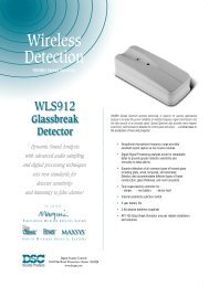
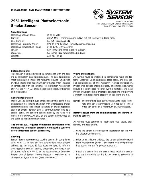
INSTALLATION AND MAINTENANCE INSTRUCTIONS<strong>2951</strong> <strong>Intelligent</strong> <strong>Photoelectronic</strong><strong>Smoke</strong> <strong>Sensor</strong>A Division of Pittway3825 Ohio Avenue, St. Charles, Illinois 601741-800-SENSOR2, FAX: 630-377-6495SpecificationsOperating Voltage Range: 15 to 30 VDCCurrent:270µA Max. Communication active but not to device in blink modeLED Current:6.5 mA Continous ONOperating Humidity Range: 10% to 93% Relative Humidity, noncondensingOperating Temperature Range: 0° to 49°C (32° to 120°F)Height:1.95 inches (50 mm) installed in BaseDiameter:4.0 inches (102 mm) installed in BaseWeight: 2.96 oz. (92 g)Before InstallingThis sensor must be installed in compliance with the controlpanel system installation manual. The installation mustmeet the requirements of the Authority Having Jurisdiction(AHJ). <strong>Sensor</strong>s offer maximum performance when installedin compliance with the National Fire Protection Association(NFPA); see NFPA 72, and all applicable codes, ordinancesand regulations.General DescriptionModel <strong>2951</strong> is a plug-in type smoke sensor that combines aphotoelectronic sensing chamber with addressable-analogcommunications. The sensor transmits an analog representationof smoke density over a communication line to acontrol panel. The sensor’s address is set by the Hand HeldProgrammer (HHP ). An LED on the sensor is controlled bythe panel to indicate sensor status.The Model <strong>2951</strong> requires compatible addressable communicationsto function <strong>pro</strong>perly. Connect this sensor tolisted-compatible control panels only.SpacingSystem <strong>Sensor</strong> recommends spacing sensors in compliancewith NFPA 72. In low air flow applications with smoothceilings, space sensors 30 feet apart. For specific informationregarding sensor spacing, placement, and special applications,refer to NFPA 72 or the System <strong>Sensor</strong> Guide ForProper Use of System <strong>Smoke</strong> Detectors, available at nocharge from System <strong>Sensor</strong> (P/N I56-407-XX).Wiring InstructionsAll wiring must be installed in compliance with the NationalElectrical Code, applicable local codes, and any specialrequirements of the Authority Having Jurisdiction.Proper wire gauges should be used. The installation wiresshould be color-coded to limit wiring mistakes and easesystem troubleshooting. Im<strong>pro</strong>per connections will preventa system from responding <strong>pro</strong>perly in the event of a fire.NOTE: The mounting base (B901) uses SEMS Plate terminalsand can accommodate 2 wires each. The 2wires can differ by a maximum of 2 wire gauges.Remove power from the communication line before installingsensors.All wiring must conform to applicable local codes, ordinances,and regulations.1. Wire the sensor base (supplied separately) per the wiringdiagram, see Figure 1.2. Prior to installation, address the sensor using the HandHeld Programmer (HHP ). See Hand Held Programmerinstruction manual for <strong>pro</strong>per operation.3. Install the sensor into the sensor base. Push the sensorinto the base while turning it clockwise to secure it inplace.D200-86-00 1 I56-1321-00
Figure 1:Remote Annunciator+ -U.L. listed compatible control panel+-++R/A-OUT+IN/OUT-IN+R/A-OUT+IN/OUT-INCLASS A OPTIONAL WIRING+R/A-OUT+IN/OUT-INA78-2665-014. After all sensors have been installed, apply power to thecontrol unit and activate the communication line.5. Test the sensor(s) as described in the TESTING sectionof this manual.CAUTIONDust covers <strong>pro</strong>vide limited <strong>pro</strong>tection against airbornedust particles during shipping. Dust covers must be removedbefore the sensors can sense smoke. Remove sensorsprior to heavy remodeling or construction.TestingBefore testing, notify the <strong>pro</strong>per authorities that the systemis undergoing maintenance, and will temporarily be out ofservice. Disable the system to prevent unwanted alarms.All sensors must be tested after installation and periodicallythereafter. Testing methods must satisfy the AuthorityHaving Jurisdiction (AHJ). <strong>Sensor</strong>s offer maximum performancewhen tested and maintained in compliance withNFPA 72 and all applicable codes, ordinances and regulations.The sensor can be tested in the following ways:A. <strong>Smoke</strong> Entry: Aerosol GeneratorAerosol generators for smoke entry testing are availablefrom a number of third party manufacturers (e.g.,Gemini Scientific). Following the manufacturer’s instructions,apply aerosol until the panel alarms.Coded signals, transmitted from the panel, can cause theLEDs to blink, latch on, or latch off. Refer to the controlpanel technical documentation for sensor LED statusoperation and expected delay to alarm.B. Sensitivity:The sensitivity of the detector can be monitored andtested by the Hand Held Programmer. Refer to HHP documentationfor sensitivity testing information. Certaincontrol panels may also monitor and test the detector’ssensitivity. Refer to control panel documentation for sensitivitytesting information. The sensitivity indication isindependent of communication. An acceptable sensitivityrange is stamped on the back of the sensor.A sensor that fails any of these tests should be cleaned asdescribed under CLEANING, and retested. If the sensor failsafter cleaning, it must be replaced and returned for repair.When testing is complete, restore the system to normal operationand notify the <strong>pro</strong>per authorities that the system isback in operation.D200-86-00 2 I56-1321-00
Figure 2:SCREENSENSOR COVERCleaningIt is recommended that the detector be removed from itsmounting base to facilitate cleaning. The detector iscleaned as follows:NOTE: Before removing the detector, notify the <strong>pro</strong>per authoritiesthat the smoke detector system is undergoingmaintenance and will be temporarily out of service. Disablethe zone or system undergoing maintenance to prevent unwantedalarms.SENSING CHAMBERSENSORSENSOR BASEA78-2666-001. Remove the sensor cover, see Figure 2. Grasp the coverand the base, rotate the cover counter clockwise and removefrom the sensor base assembly.2. Vacuum the screen carefully without removing it. If furthercleaning is required continue with Step 3, otherwise skip to Step 6.3. Remove the screen assembly by pulling it straight out(see Figure 2).4. Clean the sensing chamber and the inside of the screenassembly. Use a vacuum or clean, compressed air to removedust and debris.5. Replace the screen assembly.6. Replace the cover by locating it into the sensor base assemblyand turning the cover clockwise until it locksinto place.7. Reinstall the sensor.8. When all sensors have been cleaned and reinstalled, restoresystem operations for testing purposes and test thesensor(s) as described in the TESTING section of thismanual.9. Reconnect disabled circuits.10. Notify the <strong>pro</strong>per authorities that the system is back online.Remote Annunciator (RA400Z)The remote annunciator is connected between the R/A terminaland either the – IN or – OUT terminal as shown inFigure 1.It is not acceptable to have three stripped wires under thesame wiring terminal unless they are separated by awasher or equivalent means. The spade lug supplied withthe model RA400 is considered an equivalent means.D200-86-00 3 I56-1321-00
WARNINGThe Limitations of Property Protection <strong>Smoke</strong> DetectorsThis smoke detector is designed to activate and initiate emergency action,but will do so only when it is used in conjunction with an authorizedfire alarm system. This detector must be installed in accordance withNFPA standard 72.<strong>Smoke</strong> detectors will not work without power. AC or DC poweredsmoke detectors will not work if the power supply is cut off.<strong>Smoke</strong> detectors will not sense fires which start where smoke does notreach the detectors. Smoldering fires typically do not generate a lot ofheat which is needed to drive the smoke up to the ceiling where thesmoke detector is usually located. For this reason, there may be large delaysin detecting a smoldering fire with either an ionization type detectoror a photoelectric type detector. Either one of them may alarm only afterflaming has initiated which will generate the heat needed to drive thesmoke to the ceiling.<strong>Smoke</strong> from fires in chimneys, in walls, on roofs or on the other side of aclosed door(s) may not reach the smoke detector and alarm it. A detectorcannot detect a fire developing on another level of a building quickly or atall. For these reasons, detectors shall be located on every level and inevery bedroom within a building.<strong>Smoke</strong> detectors have sensing limitations, too. Ionization detectors andphotoelectric detectors are required to pass fire tests of the flaming andsmoldering type. This is to ensure that both can detect a wide range oftypes of fires. Ionization detectors offer a broad range of fire sensing capabilitybut they are somewhat better at detecting fast flaming fires thanslow smoldering fires. Photoelectric detectors sense smoldering fires betterthan flaming fires which have little, if any, visible smoke. Because fires developin different ways and are often unpredictable in their growth, neithertype of detector is always best, and a given detector may not always<strong>pro</strong>vide early warning of a specific type of fire.In general, detectors cannot be expected to <strong>pro</strong>vide warnings for fires resultingfrom inadequate fire <strong>pro</strong>tection practices, violent explosions, escapinggases which ignite, im<strong>pro</strong>per storage of flammable liquids likecleaning solvents which ignite, other similar safety hazards, arson, smokingin bed, children playing with matches or lighters, etc. <strong>Smoke</strong> detectorsused in high air velocity conditions may have a delay in alarm due to dilutionof smoke densities created by frequent and rapid air exchanges. Additionally,high air velocity environments may create increased dustcontamination, demanding more frequent maintenance.<strong>Smoke</strong> detectors cannot last forever. <strong>Smoke</strong> detectors contain electronicparts. Even though smoke detectors are made to last over 10 years, anypart can fail at any time. Therefore, smoke detectors shall be replaced afterbeing in service for 10 years. The smoke detector system that this detectoris used in must be tested regularly per NFPA 72. This smoke detectorshould be cleaned regularly per NFPA 72 or at least once a year.Three-Year Limited WarrantySystem <strong>Sensor</strong> warrants its enclosed smoke detector to be free from defectsin materials and workmanship under normal use and service for aperiod of three years from date of manufacture. System <strong>Sensor</strong> makes noother express warranty for this smoke detector. No agent, representative,dealer, or employee of the Company has the authority to increase or alterthe obligations or limitations of this Warranty. The Company’s obligationof this Warranty shall be limited to the repair or replacement of any part ofthe smoke detector which is found to be defective in materials or workmanshipunder normal use and service during the three year period commencingwith the date of manufacture. After phoning System <strong>Sensor</strong>’s tollfree number 800-SENSOR2 (736-7672) for a Return Authorization number,send defective units postage prepaid to: System <strong>Sensor</strong>, Repair Department,RA #__________, 3825 Ohio Avenue, St. Charles, IL 60174. Pleaseinclude a note describing the malfunction and suspected cause of failure.The Company shall not be obligated to repair or replace units which arefound to be defective because of damage, unreasonable use, modifications,or alterations occurring after the date of manufacture. In no caseshall the Company be liable for any consequential or incidental damagesfor breach of this or any other Warranty, expressed or implied whatsoever,even if the loss or damage is caused by the Company’s negligence or fault.Some states do not allow the exclusion or limitation of incidental or consequentialdamages, so the above limitation or exclusion may not apply toyou. This Warranty gives you specific legal rights, and you may also haveother rights which vary from state to state.D200-86-00 4 I56-1321-00© System <strong>Sensor</strong> 1998