1. outline - toshiba tec europe
1. outline - toshiba tec europe
1. outline - toshiba tec europe
You also want an ePaper? Increase the reach of your titles
YUMPU automatically turns print PDFs into web optimized ePapers that Google loves.
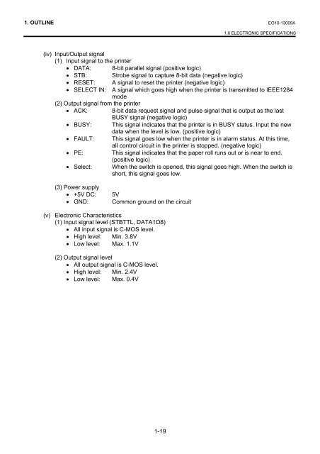
<strong>1.</strong> OUTLINE EO10-13009A<strong>1.</strong>6 ELECTRONIC SPECIFICATIONS(iv) Input/Output signal(1) Input signal to the printer• DATA: 8-bit parallel signal (positive logic)• STB: Strobe signal to capture 8-bit data (negative logic)• RESET: A signal to reset the printer (negative logic)• SELECT IN: A signal which goes high when the printer is transmitted to IEEE1284mode(2) Output signal from the printer• ACK: 8-bit data request signal and pulse signal that is output as the lastBUSY signal (negative logic)• BUSY: This signal indicates that the printer is in BUSY status. Input the newdata when the level is low. (positive logic)• FAULT: This signal goes low when the printer is in alarm status. At this time,all control circuit in the printer is stopped. (negative logic)• PE: This signal indicates that the paper roll runs out or is near to end.(positive logic)• Select: When the switch is opened, this signal goes high. When the switch isshort, this signal goes low.(3) Power supply• +5V DC:• GND:5VCommon ground on the circuit(v) Electronic Characteristics(1) Input signal level (STBTTL, DATA1Ω8)• All input signal is C-MOS level.• High level: Min. 3.8V• Low level: Max. <strong>1.</strong>1V(2) Output signal level• All output signal is C-MOS level.• High level: Min. 2.4V• Low level: Max. 0.4V1-19


