bentrup TC507 - Toma
bentrup TC507 - Toma
bentrup TC507 - Toma
- No tags were found...

Create successful ePaper yourself
Turn your PDF publications into a flip-book with our unique Google optimized e-Paper software.
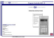
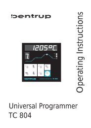
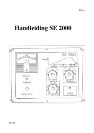
TC 507Z 1Z2Z3oprogmemoTHERMOCOMPUTER TC 507seg#prog#0p.holdk7 8 94 5 612event 1 event 2shiftvaluetmptimermpskip!selectdwellhold!3endstartstoph.min°C°C/h°F°F/hOperating Instructions
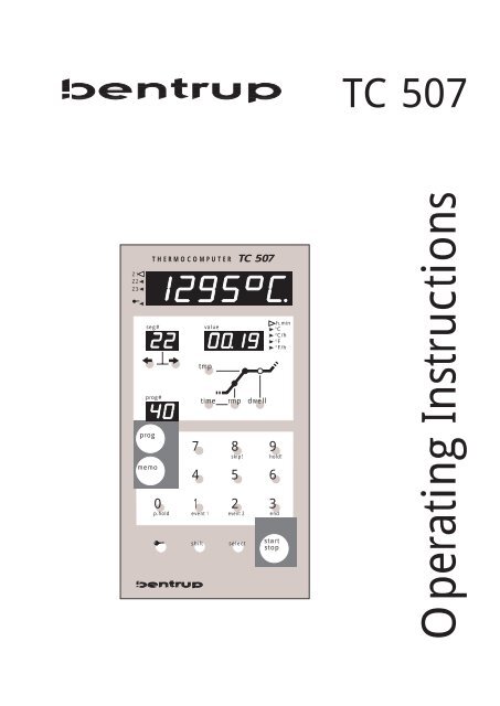
Brief Instructionsuse this keystart a programme (e.g. no. 15)prog 1event 15startstopsave the current firing curve as a programme(e.g. no. 9)memo 0skip!9hold!to lock the controller(about 3 seconds)212345Controllers Paneloprog#time rmp dwell6 1678910Z 1Z2Z3progmemoTHERMOCOMPUTER TC 507seg#0p.holdk7 8 94 5 612event 1 event 2shiftvaluetmpskip!selecthold!3endstartstoph.min°C°C/h°F°F/h1112131415171819201 zone # currently displayed2 indicator„controller keypad locked“3 segment display (blinking on enteringa programme4 key „previous segment“ on enteringa programme5 key „next segment“ on enteringa programme6 programme number called recentlty(no reading after changing values)7 calling up a programme8 saving a programme9 key to lock the controllers keypad10 shift key11 display for kiln temperatures etc.12 unit of the process of programmevalue displayed in (13)13 process value or programm valueon entering programmes14 read / change value of final temperatureof selected segment15 grafical scheme of one segment16 key to read or change dwell timeof selected segment17 key to read or change heat upspeed of selected segment (valueentered as time or ramp speed)18 keypad for entering values19 key to start and to stop a firing20 calling up additional values displayedin (11) and entering configuration
ContentsGeneral Information.............................................3Entering a Programme ..........................................5Special Notes on Entering Programmes............6ProgrammesSaving Programmes .........................................7Calling up Programmes ...................................8Starting a Programme ...........................................8DisplaysDisplay of setpoint and remaining time ...........9Checking the Current Programme....................9Displaying the Kiln Temperature....................10Locking the Controller........................................12Completion of the Firing Process........................12Manual Process Control.................................13Appendix A: Error Messages of the <strong>TC507</strong>..........14Appendix B: Data- and Error Log........................17Calling up the Data Log.................................18Calling up the Error Log.................................19Appendix C: Configuration.................................20Explanation of the Parameters ........................21Calling up the Configuration..........................23Appendix D: Weekly Switching Clock ................24Appendix E: Communication Link ......................25Appendix F: Checking Installed Options.............25Appendix G: Electrical Connections ...................26General InformationYour <strong>bentrup</strong> <strong>TC507</strong> is the top model of the <strong>bentrup</strong>controller family TC500. This controller family usesthe latest technology available and incorporates manyfeatures which haven´t been available on kiln controlsbefore. Appearing as a controller easy to use, it is ahighly sophisticated instrument with a totallyconfigurable control design allowing adaption toalmost all applications (for details see Appendix C).Reading through this manual quickly familiarizes youwith the numerous features of the <strong>TC507</strong>.Please also refer to the safety advise of your kilnmanufacturer. Make sure that the control is placed at aproper distance from the kiln and is not exposed todirect heat or radiation from the kiln.3
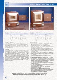
The microprocessor controller <strong>TC507</strong> allows an exactand reproduceable control of your kiln. The course ofa firing is shown in a figure which is seperated in upto 100 segments. One segment always consists of aramp (i.e. heat up or cooling) to a certain temperaturefollowed by a dwell at this temperature. Example:Temp(°C)8205405004600.00h250°C/h2:00h0:20h350°C/h0:55h0:10h0 1 2 3 4SKIP1:00h40°C/h2:00hSegmentNr.segment operation0 programme delay for delayed start (not used = 0 min)1 heating up at 250°C/h to 500°C with 20 min dwell2 heating up at 350°C/h to 820°C with 10 min dwell3 cooling at maximum speed (SKIP) to 540°C with 1 hour dwell4 cooling at 40°C/h to 460°C, no dwelltmptimermpdwellFor each segment the following values have to beentered:timeresp.rmpTemperature increase (or decrease). Can be enteredeither in degrees centigrade per hour (e.g. 250°C/h) oras time (e.g. 2:00 h). For uncontrolled hearing resp.cooling the value „skip“ is entered.tmpFinal Temperature of the ramp (e.g. 500°C). The rampends at this temperature.timeDwell time at this temperature (e.g. 20 min). Thetemperature is held for the time entered.4
Entering a Programmeseg#valueh.min°C°C/h°F°F/ho ktmpprog#time rmp dwellFollowing we are going to explain how to enter theexample described before in the <strong>TC507</strong>. Please referto the pictures shown on the left hand side.After turning on the <strong>TC507</strong> the display (13) appearsempty. Press the key „rmp“ and display (13) reads thecurrent value of the 1st segment (display (3) readssegment number). The indicators (12) point to the unitof the programme value shown (in ramps degreescentrigrade per hour). The sketch on the left hand sideshows the situation.seg#oprog#kvaluetmptimermpdwellh.min°C°C/h°F°F/hNow enter the heat up speed of 250°C/h from ourexample using the digit keys (18). The values appearin the value display (13).(the flashing segment display (3) points out that youare currently entering programme values. After 15seconds without pushing any key the controller quitsthe programming mode (display (3) stops flashing).Press key „rmp“ to get back to programming mode).seg#okvaluetmph.min°C°C/h°F°F/hNow press key (14) to enter the final temperature(which is also the dwell temperature) for this ramp.The corresponding LED in the sketch (15) lights up.Again, enter the final ramp temperature of 500°Cusing the digit keys (18).prog#timermpdwellseg#okvaluetmph.min°C°C/h°F°F/hAs the final value of segment 1 we are going to enterthe dwell time (of the temperature entered before).Press key (16), the corresponding LED in sketch (15)lights up. Enter the value of 20 minutes. If you do notwish a dwell time enter a value of „0“.prog#timermpdwellWe have now completed entering values for segment1 from our example.5
seg#okvaluetmph.min°C°C/h°F°F/hTo enter the next segment press key (5). The display (3)shows flashing the next segment number (in ourexample „2“). The display (13) reads the current valueof this segment. The <strong>TC507</strong> is now ready for thevalues of the 2nd segment.prog#timermpdwellEnter as described for the 1st segment the values forthe ramp (350°C/h), the final ramp temperature(820°C) and the dwell time (10 min).Repeat all these steps until all 4 ramps of the exampleare entered.seg#okvaluetmph.min°C°C/h°F°F/hSegment 3 requires to enter the value „skip“ foruncontrolled heating (or in this case uncontrolledcooling). This is done by entering the value of „9999“(after having pressed key „rmp“). The controller shows„SKIP“ on display (13) - see sketch on left hand side.prog#timermpdwellIn Segment 4 no dwell is needed. Simply enter „0“ asdwell time to achieve this.Entering of the example firing curve is nowcompleted. to start this firing please continue on page8 of the manual („Starting a Programme“).Special Notes on EnteringProgrammesIn general, it is not important in what sequence valuesare entered. At any time you can go back to the previoussegment using key (4) and check or alter the values.The last value in a programme must always be „end“to indicate programme end to the controller. Thepicture shows „end“ at segment 5 as our example.seg#oprog#kvaluetmptimermpdwellh.min°C°C/h°F°F/hStep to segment 5 using the key (5). Since unusedsegments on the <strong>TC507</strong> are set to „end“ by defaultusually you don´t have to enter anything. In case youentered any other value earlier you have to enter thevalue „end“ by pressing the key sequence (10)followed by „3“.shift 3endAs long as a ramp or a dwell of a segment is set to„end“ you can not step over this segment. This avoidsskipping a value unintentionally when enteringprogramme values in your <strong>TC507</strong>.6
seg#oprog#kvaluetmptimermpdwellh.min°C°C/h°F°F/hThe <strong>TC507</strong> is the first controller on the market whichprovides you with the very handy feature of entering aramp as degrees centrigrade per hour or as time to atemperature. In the current example you can entersegment 1 as 2 hours instead of 250°C/h. To do this,press key „time“ instead of „rmp“ and enter the timeof 2.00 hours.To double check you can press the key „rmp“ and youwill find the value of „250°C/h“ as you expect. Thiscalculation works in either direction.When entering an uncontrolled ramp (SKIP) in timemode you have to enter „0“ (see our example).ProgrammesDepending on programme length and some otherparameters the <strong>TC507</strong> is capable of saving up to 99firing curves as programmes. Once a firing curve hasbeen saved as a programme it can be called up easilyto be modified, saved again or simply used by startingthe firing.memo3endSaving Programmesseg#okprog# blinkingseg#valuetmptimevaluermpdwellh.min°C°C/h°F°F/hh.min°C°C/h°F°F/hTo save a firing curve that has been entered before ase.g. programme number 35 proceed with the followingsteps: Press key (8). The display (6) is blinking askingyou to enter the programme number (the decimalpoint means that a programme is to be saved).Now enter programme number 35 using the digitkeys. Display (6) reads the programme number. Theprogramme number is only shown if the current firingcurve is identical with the saved programme (which isalways the case after loading or saving a programme).Therefore if you change any value of the current firingcurve the display (6) becomes blank until you savethis programme.5 o ktmpNoteThe progamme number must always be entered as a 2prog#time rmp dwelldigit number. Example: Enter „05“ for programme no. 57
Calling up Programmesprog3end5seg#oprog#kvaluetmptimermpdwellh.min°C°C/h°F°F/hTo call up a programme previously saved press key (7)followed by the programme number (enter as 2 digitnumber as discussed earlier). After calling up aprogramme the first segment is shown.When entering an invalid programme number (e.g. 00or too high) the <strong>TC507</strong> rejects the number and thedisplay (6) reads „- -“ again.The number of available programmes depends on themaximum segment number set in the configuration(not the actual segment number). The total memory ofthe <strong>TC507</strong> can hold about 800 segments; on configuringthe <strong>TC507</strong> to maximum of 10 segments (ie 10ramps + 10 dwells) you can store 80 programmes. SeeAppendix C (parameter 12) for more details.Starting a ProgrammestartstopOn pressing key (19) the currently loaded firing curveis started. Display (3) shows the current programmenumber; graphie (15) shows whether the ramp or thedwell is being processed.Display (13) shows the remaining time in the currentsegment (counting down). This applies for ramps (theestimated time required in the ramp is shown) as wellas for dwells (remaining time is shown).seg#okvaluetmph.min°C°C/h°F°F/hIn general the reading shows hours / minutes; if thetime is less than 1 hour the indication is in minutes /seconds (unit display (12) „h.min“ is blinking).prog#timermpdwellNotesThe flashing decimal point in display (11) alwaysindicates a running programme.The flashing displays (3) and (15) point out thatdisplay (3) and (15) read programme values ratherthan state of the current firing process.8
When starting the programme as described in theexample the <strong>TC507</strong> starts at 1 hour 55 minutes (not 2hours as programmed) since the firing begins at theactual kiln temperature of 25°C (and not 0°C)Display of Setpointand remaining Timeseg#oprog#kvaluetmptimermpdwellh.min°C°C/h°F°F/hPressing the key (10) followed by key (20) changes thedisplay (13) to the setpoint temperature. Viewing thesetpoint allows you to check whether there is atechnical problem with the kiln or an error in enteringthe programme. An actual temperature near thesetpoint always confirms proper kiln operation.During ramps you can check the setpoint counting up(or down) continuously. During a dwell the setpointsstays at the programmed temperature.Pressing the key (10) followed by key (20) againswitches the display (13) back to the remaining time inthe segment.Every 15 seconds the display (13) flashes themaximum temperature of the currently processedfiring. You can disable this feature in the configurationif you prefer.Checking the CurrentProgrammeAlso during a running programme you can - as onentering the programme - call up all programmevalues using the keys (4), (5), (14), (16) and (17). If youwant to change a value you must stop the firing first(press key (19) once).When restarting a programme after having changed avalue, in general it is continued exactly at the pointwhere it has been interrupted. If you change asegment which already has been processed the <strong>TC507</strong>starts the programme from the beginning.Same applies if you totally reload a programme (forinstance by calling up a programme pressing key (7)etc. ).9
Displaying theKiln TemperatureDisplay (11) shows continuously all values of thecurrent process such as actual kiln temperature,heating power (in %), status of the control outputs etc.All values are shown in sequence by pressing key (20).The <strong>TC507</strong> is available in a version for multizonekilns. The indicator (1) points to the zone the valuerefers to. For details about multizone kilns pleasecheck out the „Technical Manual TC500 SeriesController“ available on http://www.<strong>bentrup</strong>.de.The sequence of the process values can be determinedin the configuration. By default the values shown indisplay (11) by pressing key (20) are as follows:Z 1Z2Z3Actual Kiln TemperatureThe actual temperature of the kiln is shown. Onmultizone kilns the temperatures are shown zone byzone pressing key (20). Zone no# refer to indicator (1).Z 1Z2Z3Z 1Z2Z3Z 1Z2Z3„over“: no sensor (thermocouple) connected, sensor broken,sensor wiring broken or adjusted sensor temperature exceeded„under“: sensor or wiring polarized bad. On switching polescheck color codes ! A wiring switched at both ends (!) can NOTbe determined by the controller and will cause overfiring !„invalid“: signal acquisition bad, error on determining coldjunction temperature or controllers data acquisition defect.Z 1Z2Z3Actual kiln heating in percentOn kilns switching ON / OFF only the percentage isrepresented by the on/off duty (e.g. 50% means 15seconds on and 15 seconds off).Z 1Z2Z3Z 1Z2Z3Z 1Z2Z3„channel off“: currently no control process, for instance duringprogramme delay or programme not started.„channel over“: control channel has been switched off due toerror of corresponding signal input (e.g. „over“ on input).Automatic reset when starting a programme.„channel gradient error“: For safety reasons <strong>TC507</strong> checks thetemperature increase of the kiln during full power heating. Whendropping below 3°C per 15min this error message appears. Typicalcauses: heating elements too old or broken, one phase of mainssupply missing or missing by contactor failure, short circuit ofthermocouple or wiring. Not a defect of the controller !10
Z 1Z2Z3status of the control outputsAny activated outputs are shown by their number(example shows all 4 outputs active). The function ofan outputs is determined by the configuration.process errorsZ 1Z2Z3Any process errors during the firing. On the left handside an „E“ is shown followed by an error code ifapplies (example shows code „A4“). Refer to appendixA for a complete listing and explanation of all errors.Power consumption since programme startZ 1Z2Z3Displays the total power consumption since lastprogramme start. The <strong>TC507</strong> calculates this value byadding up the heating cycles. Make sure that the kilnpower rating is properly set in the configuration (seeappendix C, parameter 1).Operation time of the heating elementsZ 1Z2Z3The <strong>TC507</strong> adds up the net operation times of theheating elements (ie. only the duration where theywere actually under power) since programme start.This allows you to check the load of the kiln or theefficiency of the heating elements.Total operation time of heating elementsZ 1Z2Z3As before but time is added up to a total value tocheck lifetime of the heating elements. Very usefulfeature to proove warranty claims as well as getting animpression about how intensive a kilns has been used.For safety reasons reset to zero only by manufacturer.Realtime clock display: day of week and timeZ 1Z2Z3Your <strong>TC507</strong> is also available with a real time clock(optional, can be installed at anytime) for automaticcommencing programmes. If your <strong>TC507</strong> is fitted withthis option this display is shown to check current dayof week and time (hours / minutes).11
Locking the ControllerThe prevent the <strong>TC507</strong> from unauthorized usage youcan lock the keypad by pressing the key (9) for about3 seconds. The indicator (2) shows the <strong>TC507</strong> is nowlocked. If the controller is locked you can for instanceonly call up values but not start or interrupt a firing.To unlock the controller press and hold key (9) againuntil the indicator (2) goes off.Completion of theFiring ProcessThe <strong>TC507</strong> processes the segments one after anotheruntil reaching the final segment (or the first segmentwith an „end“ mark as a ramp or a dwell). After thefiring is completed the segment display (3) shows an„E“ for „end“.power failureIn case of a power breakdown the firing process isinterrupted. After power is established again the firingprocess is continued from that point at which it wasinterrupted. If the kiln temperature has dropped morethan 50°C since the power failure happened the firingis interrupted (an error messages comes up - seeappendix A).Actual Duration of aSegmentIn theory a ramp takes exactly the time which isprogrammed. However, if at the beginning of a rampthe actual kiln is higher than the initial ramp temperaturethe time is adjusted accordingly. Example:Ramp 1 in 2 hours up to 500°C. If the kiln is alreadyat 250°C the time is set to 1 hour only. This alsoensures that the setpoint starts at the kiln temperature.The ramp is finished when the time has elapsed.Kiln can not followthe RampWhat happens if the kiln temperature is unable tokeep up with the programmed temperature increase?Example: Ramp asks in 1 hour to 1000°C. Your <strong>TC507</strong>handles this situation as best as possible (only if parameter#9 is set to 0 or 1): When the heating powerreaches 100% (and therefore there is no control anymore) the ramp time (or setpoint) is held (display (13)flashes „hold“). When the kiln temperature has caughtup the time continues automatically.12
To avoid a firing process locking itself because of lackof kiln power in a ramp an automatic continuation isperformed.By using the function „hold!“ you can also manuallyrelease the ramp „hold“ (press shift+9, see below).Uncontrolled Ramps(SKIP)On uncontrolled ramps the <strong>TC507</strong> stays in the segmentuntil the final temperature is reached. On multizonekilns the <strong>TC507</strong> waits for all zones. To avoid theprocess locking itself because of heat-shift betweenthe zones, there is a complex algorithm which realizesthis situation and causes a step to the next segment.Interruption of thefiring on ErrorsOn severe errors (like a broken sensor etc.) the <strong>TC507</strong>interrupts the process and shows an error message.Manual Process ControlThe <strong>TC507</strong> provides you with the feature of directlycontrolling the process flow. This feature is highlyappreciated by users of glass processing applications.Immediate Skip tonext Segmentshift 8skip!Assume that during a firing you want to skip immediatelyto the next segment (or to the dwell if you arein the ramp of a segment).Press key (10) followed by the digit key „8“ (skip!).The <strong>TC507</strong> now enters the next section immediately.Hold Processshift 9hold!Assume that during a firing you want to hold theprocess for a while, ie. to hold the temperature (incontrolled ramps - not on SKIP) or the time (in adwell).Press key (10) followed by the digit key „9“ (hold !).Display (13) shows flashing „hold“ and the firingprocess is held until the key 10 followd by key „9“ ispressed again.13
Appendix AError Messagesof the <strong>TC507</strong>Certain errors (like power breakdown, break of sensor,kiln problem etc.) found by the controller areprocessed accordingly. Important errors are showimmediately on display (11) by a unique code number(see example on the left hand side showing code„A4“). All error messages are recorded by thecontroller for post analyzation (see appendix B).Z 1Z2Z3The error codes are divided into operation or controlproblems (codes A ..), power breakdown (code B ..),internal problems (code C ..) and hardware problems(code D ..).Following is a complete listing and explanation of allpossible error messages:Error A1error on sensor inputThe control channel shuts down because of an erroron the sensor input (e.g. overflow). Error is latcheduntil next firing is started. Possible causes:• thermocouple or compensating wire interrupted• maximum temperature has been exceeded• thermocouple polarized wrong (temperature reading„under“)Error A3policeman activatedWhen exceeding the maximum programme temperatureby 20°C or more the integrated policeman shutsdown the kiln using the safety contactor (applies onlyif your kiln is fitted with a safety contactor). Thisprevents your kiln from overfiring in case the maincontactor stucks in the ON position for instance.Possible causes for over temperature:• kiln contactor stuck in ON position• a contact of the contactor has melted together14
Error A4temperature increase on full power too lowThe error message clearly points out a problem of thekiln. Possible causes:• mains fuse / phase broken, heating elements broken• heating elements too old (on high temperatures)• short circuit on thermocouple or compensating wire• contactor broken (check after operating for some time !)Error A5kiln does not follow programmed temperature increaseOther then error 4 bad programme values are thecause for this message. Firing is not interrupted !Message comes up only if enabled in theconfiguration (appendix C, parameter 9).Error A8ramp has been continued automaticallyIf the temperature increase does not follow theprogramme the ramp is held on (see section „Kiln cannot follow the Ramp“). If the controllers finds the kilnunable to catch up with the temperature the firing iscontinued and this message is shown for 1 minute.Error A9SKIP ramp has been interruptedIn an uncontrolled ramp the controller tries to matchall zone temperatures to the requested final value. Ifthe controller found the kiln unable to achieve this itcontinues to the next section. In this case the errormessage A9 is shown for 1 minute to inform the user.Error B2firing process after power breakdown continuedAfter re-establishing power supply the firing processhas been continued.15
Error B3firing process interrupted after power breakdownAfter re establishing power supply the firing processhas been interrupted due to e.g. kiln temperature hasdropped too much. If there is a digit shown after thecomma it gives further informations about the cause(e.g. B3.4 = temperature dropped too much).If this error message comes up right after turning onthe controller by the mains switch you can disregard.It just means that the controller has been turned offlast time when the firing had not been totally completed.Simply continue working by entering a programme.Error C1, C2C3, C4internal problemTechnical assistance required (C1 signal acquisitionbroken, C2 signal acqusition not within precisionlimits, C3 systembus communication error, C4systembus configuration setup mismatch).Error D1, D2D3, D4, D5hardware errorTechnical assistance required (D1 processor fault, D2RAM error, D3 bus error, D4 configuration memoryerror, D5 calibration data invalid).16
Appendix BData- and Error LogYour controller <strong>TC507</strong> is fitted with a data and errorlog. All data and errors of the entire firing arerecorded continuously by the <strong>TC507</strong>. Such featureshave not been known on this type of controllers untilnow! Don´t waste time watching a firing to discoveran error (and of course miss the most importantmoment anyway !)Data LogThe data log records all important process values (kilntemperature(s), setpoint, control outputs, times) once aminute. The data log holds the last 36 hours whichcan be inspected by the user. The recording takesplace automatically in the background (no matterwhether a firing is started or not). After turning off thecontroller all data is lost.Error LogThe error log records values only if certain errorshappen (for instance all errors decribed in AppendixA). The last 50 errors are recorded (including alldetails (temperatures etc.) like in the data log). Thisallows quick and efficient error tracking and troubleshooting. The error log is permanent so it is not lostwhen turning off the controller.Data log as well as error log record the same set ofprocess data. These are the actual kiln temperatureand kiln heating (on multizone kilns from all zones),the setpoint temperature, remaining time in segment,segment number, status of the control outputs as wellas process information.If your controller is fitted with the optional real timeclock the date / time when the data or error took placeis also recorded. This allows finding the error ofinterest quickly and enables efficient reconstruction ofthe problem.17
Calling up theData LogTo view the data logged since last power up proceedas follows: Press key shift (10) followed by memo (8).This can be done at anytime also during programmerun without interrupting the programme.Z 1Z2Z3seg#okvaluetmph.min°C°C/h°F°F/hDisplay (11) reads „L“ (for „Log“) followed by the lognumber. All other displays show the same value as innormal operation (i.e. setpoint temperature, segmentnumber etc.). As well all other process values can bedisplayed pressing key select (20). Calling up theremaining time instead of setpoint temperature usingthe keys shift (10) followed by select (20) can be donethe same way as in normal operation display.Z 1Z2Z3seg#okvaluetmph.min°C°C/h°F°F/hAdditionally the time and date (only if <strong>TC507</strong> is fittedwith the real time clock, see appendix D; if notdisplay of elapsed time since last power up) isdisplayed (see example display on the left hand side).To indicate log display other than normal operationdisplay a programme run is shown as a continuously(and not blinking) decimal point in display (11).01 2 3To call up the further values which have been recordedminute by minute the digit keys „0“ to „3“ aremisused. Press key „2“ to show next recording, press„3“ to step back to previous recording. Keeping thekey pressed to step through the logs automatically.Pressing key „0“ shows the 1st, „3“ the last record.After 15 seconds without pressing any keys the displaychanges back to normal and the current value areshown. Alternatively press keys shift (10) followed bymemo (8) to return to normal display.NoteThe controller records the set of values every 60seconds. If there is for instance a short switching inbetween two recordings it can not be seen in thedata log of course.18
Calling up theError LogTo call up the error log press key shift (10) followedby key prog (7). This can be done at anytime withoutinterrupting the programme.Z 1Z2Z3Display (11) shows „E“ (stands for „Error“) followed bythe error #. You can read out about the last 50 errors.NoteThe error that happened last (and so the most currenterror) has the lowest number and is shown firstThe kind of display, the apperance, the options to callup the values etc. are absolutely identical as describedbefore for the data log.The error log records in seqence all previous errors.The log can only be purged by the manufacturer andis very efficient and essential to track up problems inkiln or controller.Z 1Z2Z3If the error log is empty the display reads „- -“ (seedisplay shown on the left hand side). This applies toan empty data log as well.19
Appendix CConfigurationBecause your <strong>TC507</strong> can be used in a wide range ofapplications some operating parameters of thecontroller are adjustable. Usually if there were anyadjustments required they already have been done byyour supplier. Please refer to following parameter list Ifyou are interested in details:par.-no. description default unit1 power of kiln 0,0 kWh2 < reserved > 0 cm/h3 type of thermocouple (S, R, K, J) -4 maximum temperature of the kiln 1320 °C5 proportionalband 2.0 %6 integral time 200 s7 derivative time 10 s8 cyclus time (or hysteresis resp., 1.0°C) 30 s9 reaction on heat up problems 1 -10 number of kiln zones 1 -11 show flashing maximum temperature On (On/Off)12 maximum number of (half) segments 20 -13 function of the 1st additional control output 1 - function of the 2nd additional control output 0 - function of the 3rd additional control output 0 -Warning !Failure in setting up the parameter might easily causedamage to kiln and firing goods. It is the usersresponsibility to decide whether the changes madeare proper and safe. If you are in doubt do not adjustthe parameters !Some adjustments are blocked for safety reasons (e.g.changing the type of thermocouple from S/R to J/K orvice versa).20
Explanation of the parameters (see # in brackets for parameter number)power rating (1)Power rating of the kiln. This value is only used for calculating the power consumption.thermocouple code (3)Type of thermocouple: S=PtRh10%-Pt, R=PtRh13%-Pt, K=NiCr-Ni, J=FeCu-Ni. Change from S/R toJ/K and vice versa are locked for safety and technical reasons.maximum temperature of the kiln (4)maximum adjustable temperature. Please make sure that this limit never exceeds the maximumtemperature allowed for the kiln !proportional band (5), integral time (6), derivative time (7)These so called control parameters adapt the controller to the heating characteristics of the kiln.The default parameters ensure excellent results since they are continuously adapted by thepermanent auto tune feature of the controller.cycle time (8)Determines the number of switching cycles of the contactor. Frequent switching reduces lifetimeof the controller. On the other hand long switching cycles cause unsteady heating of the kiln. Thedefault value of 30 seconds has been found a good compromise for almost all applications.reaction on problems heating up the kiln (9)setting 0 the controller entirely reacts on all delays on heating up in ramps. The time counter incontrolled ramps is held („hold“) if one zone gets up to full power. This setting ensures that evenon multizone kilns if there is a lack of power the temperature in all zones is equalized as best aspossible. With this setting the actual time required for a ramp might be much longer thanprogrammed because the controller enters „hold“ cycles frequently.setting 1 (default) as setting 0 but time is only stopped if all zones are on full power. This ensurethat during a heat up ramp the kiln power of all zones is used although the temperature in somezones is not totally equalized. On single zone kilns setting 0 and 1 come to the same result !setting 2 the controller only checks the increase in temperature on full power heating. As long asa certain increase in temperature is found (min 3°C per 15 minutes) the firing is continued.setting 3 the controller does not check for any heating of the kiln. This setting should only beused if required by the application (e.g. if the kiln must be opened frequently during the firing)because operation safety gets lost. On this setting for instance a short circuit on the thermocouplecan not be found by the controller and would cause the kiln to overfire.21
number of heating zones (10)The <strong>TC507</strong> is available as 2 and 3 control zone unit. This parameter sets the actual number ofcontrol zone used. More than one control zone require a kiln designed accordingly (onethermocouple per zone, one contactor per zone). The temperature distribution on a multizonekiln is greatly improved !show flashing maximum temperature (11)setting „On“ causes the <strong>TC507</strong> to show flashing maximum programm temperature every 15seconds on display (13). This gives the user the safety of knowing that the programme has beenentered properly. If this information is confusing in your application set this parameter to „Off“.maximum number of (half) segment (12)Maximum number of segments required in your application. For most applications 10 segments(ie. 20 half segments) are sufficient. The smaller the value the more programmes you can save.The programme memory of the <strong>TC507</strong> holds up to 800 segments which gives you for instance 80programmes at 10 segments each. The exact number of programmes depends on some otherdetails (e.g. if controller is configured with EVENTs).function of the 1st / 2nd / 3rd additional control output (13) ff.The <strong>TC507</strong> can be fitted with up to 4 control outputs. On single zone kilns therefore up to 3additional control outputs are available. The function of these additional control outputs can beset to one of the following options each:0 - control output OFF (no function)1 - output for safety contactor: ON during programme run, OFF if overtemperatur is found2 - EVENT: output is programmed to ON of OFF for each half (ramp and dwell) of a segment. Upto 2 outputs can be configured as EVENT. After configuration use keys event1 or event2 toenter „0“ (=OFF) or „1“ („ON“) on every segment (actually for ramp and for dwell). Duringprogramme run the control outputs are switched to ON or OFF accordingly. This feature isused to control cooling flaps or a chimney for instance.3 - ON during programme run4 - ON during programme run as before, but not during programme delay5 - ON when programme is completed(further options on request)Parameters (13), (14) and (15) appear only depending on installed extensions of the controllerand number of zones used (ie. according to the number of available control outputs).22
Calling up theConfigurationPress key select (20) and hold it pressed for about 3seconds. The <strong>TC507</strong> enters configuration showing thefirst parameter of the list explained before. Display (3)shows the parameter number while display (13) showsthe current value.seg#oprog#kvaluetmptimermpdwellh.min°C°C/h°F°F/hUse keys (4) and (5) to step through the parameterlistexplained before. To change a parameter use keys(18). Note a number of parameters can also bealtered by using the keys rmp (17) and dwell (16).Key (9) is used as decimal point (e.g. to enter the kilnspower rating).Z 1Z2Z3To leave the configuration press and hold the key (20)for 3 seconds. If you have altered any parameters andyou would like to keep them permanently, hold keyselect (20) until the display as shown on the left handside appears („Save okay“). This special requirementavoids unintentional parameter change.LargeParameter ListThe parameter list described earlier is kept simple andcompact to make changes understandable. Parameterchanges allow the adaption of the <strong>TC507</strong> to almost allapplications. However, many functions of the <strong>TC507</strong>are hidden using this parameter list.The large parameter list includes more than 2000parameters and allows totally free configuration of theentire controller design. Zonewise control channelconfiguration, servo motor control, analog outputsand many features more can be configured.The large parameter list is selected by setting a jumperinside the <strong>TC507</strong>. Configuring the large parameter liston <strong>TC507</strong> is either done over the keyboard or byusing our Microsoft Windows based software <strong>bentrup</strong>WinConfig (only on <strong>TC507</strong> fitted with data link - seeappendix D).For further details please check the „Technical ManualTC500 Series Controllers“. This manual - as well asWinConfig - can be downloaded as PDF file on ourhomepage http://www.<strong>bentrup</strong>.de free of charge.23
Appendix DWeekly SwitchingClockThe <strong>TC507</strong> is available with weekly switching clock.This optional feature allows you to commenceprogrammes at a preset time or day of week (e.g.commence programme 2 on Monday at 01:00 óclock). You can enter as many switching jobs assegments can be entered (e.g. 20). By over lappingswitching jobs functions for instance automaticreducing temperature at night time become possibleon continuous kilns (heat up kilns weekdays at 7 AMheat up to 1200°C and bring back temperature at 5PM down to 900°C.seg#okvaluetmph.min°C°C/h°F°F/hBy pressing and holding key (7) the <strong>TC507</strong> changes tothe mode of entering weekly switching jobs (display(6) shows „cl“ for clock). Display (3) reads the numberof the job. Use the keys (17) and (16) to enter the jobs:prog#seg#oprog#seg#okktimevaluetmptimevaluetmprmprmpdwelldwellh.min°C°C/h°F°F/hh.min°C°C/h°F°F/hPress key time (16) to enter the time (e.g. 23:30). Alltimes are entered in 24h format. To supress the jobenter „off“ instead of a time (to do so press keys (10)and „0“). As on entering programmes the last job mustbe set to „end“.Now press key rmp (17) to select the day of week.Further to the normal weekday selections monday tofriday the <strong>TC507</strong> accepts „daily“, „weekday“ and„weekend“. All settings are entered as abbreviation (0-mon, 1-tue, 2-wed, 3-thu, 4-fri, 5-sat, 6-sun, 7-dly,8-w/d, 9-w/e).After pressing key dwell (16) enter the number of theprogramme to be commenced when time is reached.Enter „0“ as programme number to stop a programme.This feature can be used to stop a programme at acertain time or day of week.prog#timermpdwellTo enter next switching job enter key (5); key (4)brings you to the previous job.After 15 seconds not pressing any keys the <strong>TC507</strong>quits the mode of entering switching jobs and returnsto normal operation. All switching jobs are processedrepeatedly until suppressed on setting them to „off“manually.24
Appendix ECommunication LinkThe <strong>TC507</strong> is available with a communication link foroperation on Windows based PCs using a serial link(controller is directly connected to a serial PC port) oran industrial standard RS422/485 fieldbus. The signalsare electrically isolated for safe and proper operation.This feature allows full access to all process parameters,programmes, configuration and controlleroperation. A complete remote control of the <strong>TC507</strong>becomes possible. Follwing are some typical applications:• check and modify configuration using <strong>bentrup</strong>WinConfig (utility free of charge)• connect the <strong>TC507</strong> to your own software usingthe published data protocol• connect the <strong>TC507</strong> to your own software usingwindows DDE (simple commands like „START“;<strong>bentrup</strong> DDE fieldbus driver software required)• state of the art software <strong>bentrup</strong> WinControl forvisualization, data acquisition and recording,managing firing programmes and configurationA detailed description of the options including thedefinitions of the communication protocol can befound on our homepage http://www.<strong>bentrup</strong>.de.Appendix FChecking InstalledOptionsOn pressing key select (20) on power up the <strong>TC507</strong>shows its hardware release as well as any installedoptions. The codes shown on the display have thefollowing meanings:• number of control channels *• number of switching outputs*• number of analog outputs *Z 1Z2Z3• real time clock installed yes / no• large programm memory installed yes / no• hardware release code* The actual number can be less, please check with the code onthe controllers type label following the type of thermocouple(e.g. <strong>TC507</strong>-S-14- .. stands for 1 zone / 4 switching outputs)25
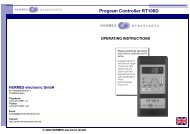
Appendix FElectrical ConnectionsSimplified Schematic of a KilnImportant Note(a)The specifications given are only an example.The electrical connections are made to ourcustomers request and sometimes differ fromthe specifications shown on this page.Pleasedouble check the required information with thefiles of your kiln manufacturer(b)(c)(d)(e)*power relay(heating)protection groundmains supply livee.g. 2nd power relay(optional)All <strong>bentrup</strong> controllers for either more than 1zone or more than 2 outputs are fitted with theHAN15DX plug described on a seperate sheet.(f)(g)(h,n)mains supply neurtral(+)(-)thermocouplea ... n: electrical links for the controllerPin AssignementsHAN7D aHAN15D aCPC14 a76c1323154ba4812711141 2 3 4 5pin no. function HAN7Da HAN15Da CPC14aa additional control output 7 C3 12b control output (live) 6 A3 14c control output (neutral) 1 B3 13d earth ground * earth clamp 11e mains supply (live) 5 A1 8f mains supply (neutral) 2 B1 9g thermocouple + 3 B5 1h thermocouple - (PtRh-Pt) 4 C5 2n thermocouple - (NiCr-Ni) 4 A5 3* earth ground must be connected!Important Note: Please compare type of thermocouple used in the kiln with the controllersthermocouple input marked on the back of the controller. Mismatch can cause severe damageof kiln and contents !26We reserve the right to make any changes without noticeOperating Instructions <strong>TC507</strong> V1.06 (C) 2001 <strong>bentrup</strong> industrial controls, inc., U.S.A.