

Dapper Tom Instruction Book - Nature Coast Hobby Shop
Dapper Tom Instruction Book - Nature Coast Hobby Shop
Dapper Tom Instruction Book - Nature Coast Hobby Shop
- No tags were found...

Create successful ePaper yourself
Turn your PDF publications into a flip-book with our unique Google optimized e-Paper software.
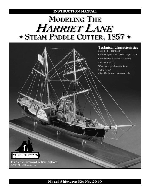
HISTORYHarriet Lane is an excellent example of the transition from sail to steam power. At the time, steam efficiency was not such that sail could becompletely eliminated. The ship was fitted with two masts and rigged similar to a topsail schooner without a gaff foresail, obviously because ofthe funnel present between the two masts.The ship was designed and built by William H. Webb in New York City in 1857 as a side-wheel gunboat for the US Revenue Service. Namedfor President James Buchanan’s Niece, the ship was 180 feet in length, beam 30 feet, and speed of 12 knots. The ship became very active in theRevenue Service and in 1858-59 served with the Navy during the Paraguay expedition. In 1861, Harriet Lane took part in the attempt torelieve Fort Sumter in Charleston, South Carolina, when that vital position was besieged by Confederate forces. While so engaged, she fired thefirst US Navy shot of the Civil War, firing across the bow of the steamer Nashville.Harriet Lane was officially transferred from the Revenue Service to the Navy in September 1861 and continued outstanding service until capturedby Confederate forces in 1863. In early 1864 she was sold and converted to a blockade runner and renamed Lavina. In late 1864 shebecame the sailing merchant ship Elliot Richie. She remained in commercial service until 1884 when she was lost off Pernambuco, Brazil.In 1984, a new <strong>Coast</strong> Guard Cutter was named Harriet Lane, honoring the original ship. Information on the history and etchings of both theold and new ship can be found on many internet web sites.The kit of the Harriet Lane was developed in 1965 by John Shedd, the original owner of Model Shipways in Bogota, New Jersey. The planswere drawn by James F. Berge. While the plans are reproduced from the original, the kit has been updated and reissued by Model Shipways,Inc., the owner and manufacturer of Model Shipways kits. Kits are sold and distributed by Model Expo, a division of Model Shipways, Inc.New instructions are provided along with a more complete set of supplies for building the model. The fittings are now cast from lead-freeBritannia metal and laser-cut wood parts have been added.Because of the small scale used for this model, a lot of detail for the hull and rigging was simplified or omitted when the plans were developed.To try and add more detail may result in over scaling many items. So, use caution if attempts are made to enhance the detail. Always keep thescale in mind.Construction Stages & Table of ContentsHistory .....................................................................................................2Before You Begin .......................................................................................3How To Work With The Plans & Parts .....................................................3What You’ll Need to Start Construction .................................................3-4Painting & Staining.................................................................................PgStage A: Shaping the Pre-Carved Hull1. Using the Templates ..............................................................................42. Carving the Hull ...................................................................................43. Carving the Bulwarks ............................................................................5Stage B: Completing the Basic Hull Structures1. Installing the Keel, Stem & Sternpost ....................................................52. Installing the Rudder .............................................................................53. Drilling the Larger Holes in the Hull.....................................................54. Holes to be Drilled as Work Progresses...............................................5-65. Planking the Deck & Installing the Waterways......................................66. Cutting Out the Gunports, Paddle Box Openings, & Bowsprit Slot......67. Installing the Deckhouse .......................................................................68. Installing the Paddle Box Sponsons, Paddle Box, & Paddles ...............6-79. Installing the Knightheads, Bulwark Cap Rail, Catheads,& Bow Rail ..........................................................................................710. Installing the Outboard Shear Strake ...................................................711. Installing Gun Port Lids ......................................................................7Stage C: Mounting the Hull...........................................................7Stage D: Adding the Hull Details1. General Notes........................................................................................72. Small Vents, Compass, Hawse Pipe Lips, Deck Bitts, Bell,& Windlass ..........................................................................................73. Guns .....................................................................................................74. Davits & Boats ......................................................................................75. Fife Rails................................................................................................76. Funnel, Funnel Base, Guys, Steam Vent Pipe, & Whistle.......................87. Kingposts & Guys .................................................................................88. Anchors .................................................................................................89. Ladders, Bridge, & Rail Stanchions .......................................................810. Steering Wheel Box, Skylights, & Companionways .............................8Stage E: General Masting & Rigging Information..............8-9Stage F: Mast & Spar Construction........................................9-10Stage G: Standing Rigging.......................................................11-12Stage H: Running Rigging.......................................................13-14Bibliography.................................................................................14-152
metal fittings. Lightly sand the primeditems. Use a spackling compound such asPic-n-Patch brand to fill any scratches anddefects, then re-prime.Stains & Finishes:For natural finished wood, use a protectivecoating after staining, such as low-sheenpolyurethane varnish. You can also use anoil-resin mix like the ones sold by ModelExpo or Minwax.For the spars, Model Expo stain or Minwaxcan be used. These are a combination stainfinishthat will provide a light tone to thewood. The staining of all wood parts shouldbe done before gluing, especially if any CAglue is used. The stain will not penetrate driedglue and leave ugly white areas in the finish.Brushes & Procedures:Use good quality soft sable or synthetic hairartist’s brushes. A small pointed brush isgood for details. For the main hull areas, usea 1/4" to 1/2" flat brush.Before painting, clean the model with a tackrag. Apply your paint in smooth and evenstrokes, overlapping them as you go. Thinthe paint enough to eliminate brush strokes,but not run. You will need three or fourcoats of the light colors to cover the greyprimer and maybe only two coats of thedark. Check your finish between coats andsand and add spackle as necessary to get ridof any blemishes.You will be told how to mark the waterlinelocation in Stage A. At this line, and anywhereelse two colors meet, use maskingtape. Electrician’s black plastic tape or any ofthe hobby tapes made of plastic film areideal. They leave a nice edge and are notoverly sticky. Do not use drafting tape unlessit is Chart-pak brand. The edges are somewhatwrinkled and paint may run underthem. A good trick; seal the edge of maskingtape with a clear flat finish and let dry thoroughly.This will really prevent paint fromrunning under the tape.Sanding alone will not shape the hullenough to precisely match the hull lines.Some carving is required, especially at therail, keel, bow, & stern areas.1. Using the TemplatesFor exact carving to hull lines, a template isrequired for the hull profile and each of thestations. You will find templates printed onheavy stock paper in the kit. Cut the templatesout carefully with a No. 11 hobbyknife. Do not use scissors! You will want anice smooth edge.2. Carving the HullCut a wooden block from scrap to about 3”x 1” x 3/4” thick. Screw the block to thedeck so the model can be held in a benchvise for carving. First, check the accuracy ofthe profile and correct it as necessary. Sincethere is a separate profile template for theforward and aft areas, make sure you don’tget a knuckle at the keel. Keep the keelstraight.Next, mark the centerline, rabbet lines(where hull meets keel) and station lines onthe model (Figure A-1). Note that the widthat the keel, stem, and sternpost (rabbet torabbet) is 3/32". Keep these areas flat as the3/32" keel, stem, and sternpost will be gluedon later. Place the station marks on the centerof the hull bottom and on top of the railsso the marks won’t be carved off as youwork. Also, add marks for the width of thehull at each station on top of the rail. Measurethe marks from the centerline of themodel so the marks will be the same portand starboard.As shown on the sketch, a good way to startis to cut a slope at the rail back to the hullwidth marks to establish the width of thehull at the rail for the entire hull length. Younow have a line to carve to as you fit thetemplates. Next, start carving approximatelySTAGE A: SHAPING THE PRE-CARVED HULLFIG. A-1 MARKING THE HULLWIDTHAT RAIL3/32"MEASURE FROMLINES PLANMARK HULLWIDTHS ATEACH STATIONRABBETRAIL3/32"at mid length (maximum beam) andprogress forward, then aft, using chisels andgouges to cut away excess wood. Avoid carvingagainst the grain by shifting forward oraft until you find a spot where you are goingwith the grain. Basswood carves easily, soyou probably won’t have much problem withthe grain.4WOOD TO BECUT AWAY3/32"MARK CENTERLINEMARK STATIONS &HULL WIDTHSON TOP OF RAILMARK RABBET LINESMARK ALLSTATIONLINESSTART CARVING LIKE THISTO ESTABLISHHULL WIDTH AT RAILFITTEMPLATESCarve very slowly and take off a little woodat a time. Fit the templates as you go. Carveuntil the template fits reasonably well, thenuse sandpaper to obtain the final shape. Atfirst the templates will not fit very well, especiallyat the stern where a fair amount ofwood needs to be carved off. You must comparethe template to the hull and visuallydecide where to remove wood. Cut a littleoff, then re-check the template.Finally, draw a few horizontal pencil lines(like waterlines) and the vertical station lineson the hull. Use these to visually check theshape of the hull. Hold the hull at variousangles, and look to see if the pencil lines arefair (even). If you have any unfairness, dipsor bump, they can usually be found with thisvisual check. You can also use a stiff stick of
wood, about 3/32” square, and lay it on thehull at various locations. Dips and bumps inthe hull will show up under the stick.3. Carving the BulwarksMake yourself a temporary cradle to securethe hull while carving. This cradle also willserve to hold the model for most of theremaining work. Make the cradle so themodel sits in it with its waterline parallelto the baseboard and table. The tops of thecradle should be below the waterline.Later, when you are ready to paint, attacha pencil on top of a wooden block andslide it along the table to mark the locationof the waterline.The machine-carved hull has bulwarksthicker than scale so they won’t breakwhile inside the kit box. The upper surfaceis cut to the underside of the bulwark caprail. After you carve the outside of thehull, the bulwarks will be thinner. If morethan 3/32" thick it will be necessary toFIG. A-2 CARVING BULWARKSUSE GOUGE FIRSTcarve the inside of the bulwarks. The caprail on top of the bulwark is 1/8" wide somust cover the bulwark. This is the mostdifficult part so work slowly as you carve.After carving, sand the surfaces smooth(Figure A-2). If you happen to have orwant to buy a powered rotary tool like aDremel, there are many cutters available toquickly reduce the bulwark thickness.SMOOTH WITH CHISELNote: The height of the bulwarks above thedeck must be between 11/32" and 3/8"inboard. Some of the machine carved hullsmay not provide this height. If this is thecase, add wood strip on top of the bulwarkto build up to the correct height. Makesure this is done before you cut out theopenings for the gunports and paddle box.STAGE B: COMPLETING THE BASIC HULL STRUCTURES1. Installing the Keel & StemThe keel, stem & sternpost are cut frombasswood. Taper the stem and install theparts. You might as well add the Eagle Figureheadcasting at this time (Figure B-1).Use pins or dowels to position the partsbefore gluing. Scrape off any glue squeezeout.Fill any gaps remaining at the gluejoints with wood filler and then sand..2. Installing the RudderCut the rudder from stripwood. It can beshaped and installed now or later. The rudderis tapered and has a round front edge.The rudder stock can be made long enoughto go thru a hole in the hull all the way up tothe underside of the steering wheel box. Asan option, forget the hole, cut the stock atthe bottom of the hull and add the top portionas a separate piece when you make thesteering wheel box. For the pintles & gudgeons,fake them using the self adhesivecopper strip included in the kit. See FigureB-2 for construction.3. Drilling the Larger Holesin the HullBefore going any further with the details, drillall the large holes in the hull. These wouldinclude mast holes, holes for the airport fittings,and pilot holes in the keel for screws formounting the model on a display base.4. Holes to be Drilledas Work ProgressesThere will be a other smaller holes to drill asthe work progresses. For example, the hawseholes for the anchor cable are drilled throughFIG. B-1 KEEL, STEM, & STERNPOSTSTERNPOSTFIG. B-2RUDDERRUDDERSTOCKLOSSPREVENTERCHAINTAPER5KEELCARRY STOCK TOUNDERSIDE OFSTEERING WHEELBOX OR CUT-OFF &ADD SEPARATE PIECEABOVE DECKSELF-ADHESIVECOPPERTAPE TOFAKEPINTLESANDGUDGEONSFIT FIGUREHEAD HEREPIN OR DOWEL (TYPICAL)TAPERSTEMCUT FROMSHEETFIG. B-3 DECK & WATERWAYSIDEVIEWWATERWAYSCOREDDECK SHEET
the bulwarks forward. Holes will be requiredin the deck and cabin for fittings such as fiferails, compass, davits, and vents. You willalso need to drill holes for inserting eyeboltsthat hold blocks for the rigging, jackstays,chain guys for the funnel and kingposts, forbelaying pins, and rail stanchions.5. Planking the Deck & Installingthe WaterwayThe deck planking supplied in the kit is ascored basswood sheet. To represent caulkedseams darken the scored lines. To fit thesheet, first make a paper pattern of the deckarea. Make sure the scored plank lines areparallel to the centerline when the sheet isinstalled. Glue the sheeting down withcontact cement or airplane-type cement(see gluing notes in the Painting andStaining Section).Waterway - Along the inside of the bulwarks,add a 1/32" x 1/16" waterway strip on top ofthe decking (Figure B-3). For the curved areasat the stern and bow where you cannot easilyedge bend the strip, cut the waterway fromthe 1/32" wood sheet included in the kit.6. Cutting Out the Gunports,Paddle Box Openings, &Bowsprit SlotAs noted earlier, make sure the bulwarkheight is correct before cutting openings.Cut the openings according to the plan. Usea fine razor saw blade or jewelers saw to cutthe vertical sides and then cut the bottomwith a hobby knife. The openings for thepaddle box sponsons and the paddle boxesare cut flush with the deck. The bottom ofthe gunports and bowsprit slot are above thedeck so measure the depth from the plan.7. Installing the DeckhouseThe deckhouse is composed of two laser-cutparts. Glue the pilot house raised portion onthe front of the large deckhouse part.Smooth out the joint and fill with woodfiller if necessary (Figure B-4).Before gluing the deckhouse on the hull, thesides should be painted. The kit contains apaper sheet of patterns to make painting easier.Cut out the patterns and white gluethem to the sides of the deckhouse andaround the pilot house in locations shownon the plan. Make sure they are smoothedout so no glue lumps build up under thepaper patterns. Once dry, coat the paperwith some flat clear coat.Since the sides of the deckhouse is white,maybe you need only paint where wood orglue stains are showing. But painting all thewhite areas of the pattern would look better.The black printed lines can be left as is toshow through. All these black lines would bevery difficult to paint. If you do get paint onsome of the lines, you can touch up the lineswith paint or black ink. The pilot housewindow glass will look best if painted a paleFIG. B-4 DECKHOUSEROUND THECORNERSTOP EDGE MOULDING(TYPICAL)FIG. B-6 PADDLE BOX SPONSONS & ASSEMBLYOPENING IN BULWARKLASER-CUTSPONSONBRASS RODSUPPORTS(BOTH ENDS)HULLLASER-CUTDECKHOUSEPAPER PAINTINGPATTERN (TYPICAL)COAMING(TYPICAL)LASER-CUTPILOT HOUSETOP PORTIONblue as if reflecting daylight. If paintedblack, it would obscure the window frames.Add 1/32" thick coamings and top edge trimall around the deckhouse for an authentictouch. The coamings and trim should alsobe painted white. When gluing the coamings,have the bottom just slightly below thedeckhouse. Pre-fit the deckhouse on thedeck and sand the bottom of the coamingsto account for deck camber and to fit downon the deck without any gaps under thecoaming. When all is well, glue the deckhouseto the deck.8. Installing the Paddle BoxSponsons, Paddle Box & PaddlesPaddle Box - Each paddle box is composedof two laser cut parts. First, glue the twohalves together and smooth out the joint.Next, round the outboard ends to the radiusFIG. B-5 PADDLE BOXWHEEL BOXWATERCLOSETHOLE FORAIRPORTMOULDING SHAPEDOUTBOARDCORNERA - PLAN VIEWROUNDTHE OUTERCORNERSGLUE 2HALVESTOGETHERLASER-CUTDECORATIVEPIECEB - END VIEWROUNDTHE OUTBOARDWATER CLOSET TOPCOMPLETEDPADDLE BOXPADDLE WHEELCASTINGSWOODPADDLESshown on the plans (plan view). Then,round the outer tops of the water closets(ends of the paddle box) per the section viewon Plan Sheet 1 (Figure F-5).Drill holes and install the airports (large onesin the kit) on each end of the water closets.Paint the outer side of the paddle boxesblack in way of the paddle wheel. Paint thelaser-cut decorative sides white, with theindents black or gray, and glue them to thesides of the paddle box. The black paddlebox will show thru the slots in the decorativepiece to appear as holes. Add 1/32" squaremoldings which are in line with the bulwarkrail. The water closet doors inboard can beoutlined with ink, painted, or drawn on apaper sheet and added like the deckhouse.Paddle Box Sponsons - The sponsons arelaser-cut parts. Drill holes in the bottom ofthe sponsons and the hull side for the6
supports which are made from brass rod.Before installing the sponsons on the hulladd the paddle box and the paddle wheelframes (castings). Make sure the alignmentis correct. The centerlines of the wheel mustbe in line with the centerlines of the paddlebox. Cut the wooden paddles from stripwoodand glue onto the frames. Thesponsons fit in the opening cut in the bulwarks.The bottom of the center portion ofthe sponsons fit on top of the deck and thefore and aft ends butt against the hull side.After gluing the sponsons in place, add therod supports (Figure B-6).Paint the underside of the sponsons and thepaddle wheel black.FIG. B-7 CAP RAIL, KNIGHTHEADS, CATHEADS, & BOW RAILCAP RAILCATHEADKNIGHTHEADBOW RAILSLOT INWAY OFBOWSPRINTSLOTCUT CHOCK9. Installing the Knightheads,Bulwark Cap Rail, Catheads,& Bow RailOn each side of the bowsprit opening,install the knightheads at the bow. The caprail is 1/32" x 1/8" strip. However, like thewaterway, cut the curved areas from 1/32"sheet. After installing the cap rail, add thebow rail. Cut the catheads from wood andadd at the end of the bow rail port and starboard(Figure B-7).10. Installing the OutboardShear StrakeThis is a 1/32" square strip on the outside ofthe hull as shown on the plans. Note that thestrip lines up with the bottom of the gunports,not at deck level. The deck is actuallya little below the strip.11. Installing Gun Port LidsCut the gun port lids from 1/32" sheet.Use the self adhesive copper tape for thehinge straps. Glue the lids open at top ofthe gunports.Before proceeding with additional work it isbest to mount the hull. This step will helpprevent details from becoming damaged duringhandling and will allow you to make anyalignments that require a true waterline. Propermounting of the hull is very important andwill allow the accurate building and aligningof the remainder of the model. The kit doesnot include any parts for mounting. However,the following suggestion is provided.1. General NotesDon’t forget to file off any flash on Britanniametal fittings, clean the fittings and then primethem with grey primer before final paint.Locate deck fittings and mark their position.This can be done by measuring from mastholes, station lines and centerline (tick off fromplans). Use as little glue as necessary on parts.Watch out for that glue squeeze-out. It’s hardto remove if left to harden.2. Small Vents, Compass, HawsePipe Lips, Deck Bitts, Bell,& WindlassThe castings for the small vents, bell, andcompass will require holes drilled for the fittingsbefore installing. Glue the hawse pipelips, deck bitts, and windlass in place.3. GunsGlue the barrel castings on the carriage castingsand glue the guns to the deck at theirSTAGE C: MOUNTING THE HULLMounting Board with Two Pedestals - Acommon mounting for ship models is a woodenbaseboard with two wooden or brasspedestals. For a homemade board, a nice lookinghardwood such as cherry, walnut, andmaple would be ideal. You can round the topedges of the baseboard, or cut a simple chamfer.If you own a router, or can borrow one,you will be able to cut a nice fancy edge on thebaseboard. Stain the base if necessary and giveit a few coats of varnish or finish like Minwax.STAGE D: ADDING THE HULL DETAILSgunports. Note that the Parrot Rifle is locatedon the port side forward, but most likely itwas moved about on the real ship.4. Davits & BoatsThe boat castings can be detailed with woodenseats if desired or to avoid such detail, adda cover over the boat top with paper or cloth.Because of the small scale, use of blocks forlifting the boat by the davits would be a littletedious. Suggest hanging the boats by a wireand glue the boat to the davits. Drill holes forthe davits in the deck and glue the davit andboat in place. Add the davit guys and boatstraps (gripes) as shown on the plan with tanline. Install cleats inboard the bulwarks asshown on the plans for belaying the lines.5. Fife RailsThe fife rails are composed of two side railsand a cross bar. The side rails are Britanniacastings. Make the cross bars from wood.Drill holes in the rails and cross bar and insert7The pedestals could be wood or brass. ForHarriet Lane, the pedestals should be locatednear station 5 and 10. The waterline shouldbe level. If not, you can add a brass shimunder one pedestal to correct it.Baseboards and pedestals are available fromModel Expo (www.modelexpo-online.com).FIG. D-1 FUNNELSTEAM VENTPIPE TOPCASTINGWIRESUPPORTSBRASSRODGUYCHAINBASECASTINGthe belaying pins. Holes will also be requiredin the deck for the fittings.EYEBOLTS,P/SSELF-ADHESIVECOPPERTAPEFUNNELWOODDOWELWHISTLECASTING
FIG. D-2 DECK STRUCTURESDOORSSLIDE COVERSLIDERAILSPAINTED GLASS& BARS1/32" TOP OR JUST ADD SIDE STRIPSTO CREATE AN OVERHANGSKYLIGHTCARVEDBLOCKSTRIPOPTIONCOAMINGFORWARD COMPANIONWAYSTEERING WHEELCASTINGCARVEDBLOCKRUDDER STOCK FROM RUDDEROR SEPARATE PIECESTEERING WHEEL BOXCORNER SUPPORTS -LATHE-TURNED SHAPE OR PLAIN DOWEL6. Funnel, Funnel Base, Guys,Steam Vent Pipe, & WhistleCut the funnel dowel to length and fitinto the base casting. Note the angle of thefunnel. Add the bands on the funnel withself adhesive copper tape, then add eyeboltson the funnel and on the hull forsecuring the guy chains.The steam vent pipe top is a casting in the kit.Use a 1/32" dia. brass rod for the pipe portionand secure it to the funnel with a wire strut.The bottom of the rod fits in a pre-molded holeon the aft side of the funnel base casting. Thewhistle casting is glued in a pre-molded hole onthe forward side of the funnel base casting.Glue the assembled funnel to the cabin andadd the guy chains (Figure D-1).7. Kingposts & GuysThe kingposts are 1/16" square basswood.Glue in place, but first add eyebolts for theguy chains. These kingposts are supports forthe paddle boxes.8. AnchorsGlue the cast stocks onto the anchors. Addthe anchor chain and glue the anchors to therail next to the catheads. Carry the chain thruthe hawse pipes and wrap around the windlass.The tackle for the catheads is omittedbecause of the small model scale.9. Ladders, Bridge, &Rail StanchionsCut the ladders to length and glue on thedeckhouse. The bridge platforms are 1/16" x1/4" wood. Install on top of the paddleboxes, but first, drill holes and add the railstanchion castings. After installation, add therails using brass wire or black line.10. Steering Wheel Box, Skylights,& CompanionwaysThese structures are to be made from woodstrips. Skylight glass and bars can be paintedon. The steering wheel is a Britannia casting.Figure D-2 illustrates a method for makingthe steering wheel box and the forward companionwaywhich also has a skylight. Otherstructures are similar.STAGE E: GENERAL MASTING & RIGGING INFORMATION1. Rigging IdentificationThe rigging is identified by name on therigging plan but not completely. The staysare all identified simply as stays. Theinstructions will be more specific, specifying“forestay” for example. If you are notfamiliar with the names and functions ofrigging lines, the book How to Build First-Rate Ship Models From Kits by BenLankford contains a description of Nauticalterms (See Bibliography).2. Sails and Sail LinesThe model is designed, and parts are provided,only for a model without sails and theinstructions address this approach. If youdesire to add sails you can consult the booksin the bibliography which will provide mostof the details necessary. Keep in mind,however, that a lot more parts and materialwould be required such as pin rails, sheaveholes, additional blocks and rigging line, andsail material.3. Block, Deadeye, & Line SizesBlocks & Deadeyes - 3/32" long singleblocks and 3/32" diameter deadeyes aresupplied.Rigging Line - Use the 0.008" tan line forall running rigging. The black standingrigging line is supplied in two sizes. Useaccording to the following:0.012" line - Use for topmast shrouds,topmast stays, footropes, stirrups, ratlines,and backstays.8FIG. E-1 SEIZINGSSTART WITH ACLOVE HITCHGLUESEIZING SMALL BLOCKOR AROUND SPAR USINGA SLIP KNOTWRAP, THENGLUE &CUT-OFFENDS
0.018" line - Use for lower shrouds, mainstay, fore stay, jibboom and bowspritshrouds, and slings for lower yards.4. Applying Beeswax to the LinesBefore placing rigging lines on the model,run the line through a block of beeswaxseveral times. Then, run the line throughyour fingers. This heats the wax slightlyand rubs it into the line. The beeswax willcut down on fuzz and protect the linefrom moisture.5. Seizing Rigging LinesSeizing of lines (binding or securing twolines or different parts of the same line)can be done as shown in Figure E-1. Toprevent seizings from unraveling, add atouch of CA glue. For seizings, use thesmallest line in the kit or sewing thread.FIG. E-2 BLOCK STROPSGLUETWISTUSING WIREGLUECLOVE HITCHWITH THREADGLUE6. Block StropsA strop is an iron or rope band or grommetaround the shell of a block forAROUNDA SPARGLUEUSING LINEGLUE, THENCUT-OFF ENDSSEIZEWITHTHREADattaching lines. The blocks in the kit arefairly small so it is not easy for you to createthe exact detailing. Some modelingshortcuts are in order (Figure E-2).Most references call a mast a mast, and anythingelse such as a boom, yard, gaff, andbowsprit a spar. Let’s stick with that definition.There are two mast assemblies for the HarrietLane. They are a foremast & mainmast. Bothare built up in two sections. Each of the sectionsare connected at the doublings (whereupper and lower masts overlap) by mast capsand trestletrees. The mast caps are castings inthe kit. The trestletrees along with the crosstreesare to be made from wood.1. Shaping the MastsTapering the Masts and Spars - Mast andspars are tapered. The best way to taperthe masts and spars from dowels is start atmaximum diameter and cut or sand thedowel into squares, then by sanding thecorners into a round shape (Figure F-1).Shaping the Mastheads & Heels -Generally, most ships have squaremastheads and square heels on upperround masts. For this small model, leavingthe heads and heels round is suggested tosimplify the work. The top of the lowermastheads, however, needs to be square tofit the cast mast cap.2. Mast DetailsMainmast - Add a boom rest on this mastnear the deck.Topmasts - Both topmasts have two riggingstops where the upper stays and backstays areseized. A rigging stop is simply a shoulderformed by the reduction of the mast diametergoing above. The shoulder prevents the linesfrom sliding down the mast. For this model,the topmasts are small in diameter. To actuallycut the shoulders would weaken the mastand it could break. Instead, wrap the mastwith thread or paper strip and glue to form afake shoulder.STAGE F: MAST & SPAR CONSTRUCTIONFIG. F-1 TAPERING DOWELSFIG. F-2 MAST DETAILSREAL SHIPTOPMAST RIGGING STOPSBOOM REST2-HALVES OR1-PIECE& SLIDE-ONFigure F-2 illustrates the above details.3. Mast AssemblyMake the trestletrees and the cross-treesfrom stripwood. The mast cap is a casting.Assemble the masts as shown in Figure F-3.4. Shaping & Detailing the SparsYards - Shape the yards in the same manneras the masts. The maximum diameterof each yard is at its center. Taper the yardsoutward from each center. Cut a shoulderon each end of the yards which is a stopfor lifts, braces, and footropes.Jackstays consists of a series of eyeboltsthru which a rod or line is passed and9MODELCHOCKS(OPTIONAL)SAND 4 SIDESTO SQUARE1 2 3WRAPTHREAD& GLUEFIG. F-3 MASTHEADCROSS-TREESLOT FORSHROUDSHEEL OF MASTOR CENTER OF A YARDMASTCAPCASTINGTOPMASTTRESTLE-TREELOWER MASTfixed at the ends of the yard. The line andeyebolts are used for attaching the head ofa sail and the footrope stirrups. Note thatthe eyebolts are on top of the yard butslightly forward of the yards centerline.While you are detailing the yards youmight as well add the jackstay lines afterthe eyebolts are installed. Use either brasswire or line for the jackstays. Figure F-4illustrates a typical yard. The Figure showssome optional fittings at the center of theyard which would be appropriate for thetime period of this ship.
Boom & Gaffs - The boom and gaff alsotaper, but the maximum diameter of eachspar should be about one-third from itsfore end. Like the yards, cut a shoulder atthe outer end of these spars. The boomand gaffs require that jaws be added totheir throats for joining to the masts. Thejaws are made from wood (Figure F-5).Bowsprit, Jibboom, & Dolphin Striker -The bowsprit is tapered forward from thehull. Inboard, the bowsprit is square so asan option use square wood for thebowsprit instead of the dowel. The dowelcould still be used and left round for theentire length. At the outer end, cut asquare shape to fit the bowsprit cap to bemade from wood. Add the bees for thefore topmast stays. Inboard there is a bitton each side of the bowsprit heel. Makethese from wood. The gammoning strapsecuring the bowsprit to the stem, and thebands for the bobstays can be made fromself adhesive copper tape. Put eyebolts inthe bottom of the band for the bobstays.The jibboom should be straight from theaft end to the bowsprit cap, then taperedforward of the cap. At the outer end cut ashoulder for the jibboom shroud seizings.Drill two holes for the head stays to passthrough (sheaves on real ship).The Dolphin Striker (or martingale) is asimple tapered round spar. At the bottomof the spar add a bent wire cleat for headstays to pass under. Drill a hole in theunderside of the bowsprit cap and insertthe dolphin striker.Figure F- 6 illustrates the bowsprit,jibboom, and dolphin striker details.FIG. F-4 YARD DETAILSFWDJACKSTAYEYEBOLTSSHOULDERLOCATE EYEBOLTSFORWARD OFYARDS CENTERLINEJACKSTAYFWDBAND & EYEBOLTLOWER YARD - FOR SLINGUPPER YARDS - FOR HALLIARDFIG. F-6 BOWSPRIT, JIBBOOM, & DOLPHIN STRIKERBITTS ON DECKOPTIONAL DETAILSOPTIONAL WOOD CHEEKFOR TOPSAIL &TOPGALLANT YARDSJIBBOOMHOLESFOR STAYSBEES P/SPARRELSHOULDERDOLPHINSTRIKERBOWFIG. F-5 BOOM & GAFF JAWSPARREL LINEINBOARDWOODCAPBOWSPRITGAMMONING STRAPSELF-ADHESIVECOPPER TAPEBOBSTAY BAND WITH EYEBOLTSELF-ADHESIVE COPPER TAPECLEATS(BENT WIRE)10
1. Shrouds & BackstaysThe lower shrouds and backstays are setup with deadeyes and lanyards at the railand attached along the outside of the shipusing chain plates. The lower deadeyestrops and chain plates are to be made ofwire provided in the kit. Cut a notch inthe rail and in the shear strake strip for thechain plates, then add a thin strip over thenotches. Figure G-1 illustrates.For this small scale model, setting up thedeadeyes is a difficult task if done properly.A simplified approach is recommended. Itis suggested you reeve the lanyards beforenailing the chain plates to the hull andbefore installing the shroud or backstay toestablish the correct deadeye spacing. Makea wood jig to hold the deadeyes at the correctspacing and to aid in reeving thelanyards. Install the chainplates on thehull, then install the shrouds and backstays(Figure G-2). The sketch also shows theproper sequence for the shrouds goingaround the mastheads. The backstays seizeto the topmast rigging stops.Note: A commercial jig for spacing deadeyesand reeving lanyards is available fromModel Expo (www.modelexpo-online.com)After the shrouds are in place, proceed toadd the ratlines and the sheer poles (woodstrip just above the upper deadeyes). Onthe real ship, ratlines would be seized tothe inner shrouds with clove hitches andby eyesplices on the outer shrouds. Forthis small scale model, simply glue blackline or sewing thread to the shrouds andcut off at each end.The topmast shrouds are set up similar tothe lower shrouds but instead of havingchain plates they set up to futtock shroudsat the mast (Figure G-3).2. Foremast (Head) StaysThe name for the stays at the foremast fromthe lowest to the highest are forestay, fore topmaststay, jib stay, and fore topgallant stay.Forestay - The forestay is a double linewrapping around the masthead. Seize thedouble line together just below the mastheadand just above the bowsprit. Set thelower ends to eyebolts on each side of thebowsprit at the bow. The eyebolt is shownin a detail on Plan Sheet 1.Fore Topmast Stay - This is also a doubleline. Seize the two lines together just belowthe lower topmast rigging stop and just abovethe bowsprit. The ends then pass port andstarboard thru the bees on the side of thebowsprit. Though not shown on the plans,the lines should then go to the bow on eachside and set up to an eyebolt. Place the eyeboltsjust a little aft of the stem and just belowthe cap rail.STAGE G: STANDING RIGGINGFIG. G-1 DEADEYES AT RAILRAILNOTCHSHEARSTRAKEJib Stay - The jib stay is a single line. Seizethe top around the lower topmast rigging stop(on top of the fore topmast stay). The bottomgoes thru a hole in the jibboom, then underthe starboard cleat on the dolphin striker,then to an eyebolt on the starboard bulwarkunder the cathead.Fore Topgallant Stay - This stay is seizedaround the upper topmast rigging stop,then goes thru a hole in the jibboom, thenunder the port cleat on the dolphin striker,then to an eyebolt on the port bulwarkunder the cathead.Note - The part of the two forward staysunder the jibboom and the port and starboardends labeled “A” and “B” on the plans aremore properly called martingale stay and martingalebackstays respectively.See Figure G-4 for some head stay details.3. Bowsprit & Jibboom RiggingBowsprit Shrouds - These are port andstarboard. Seize the outer end to an eyeboltin side of the bowsprit cap and the inner11COVERSTRIPBACKINGLINKFIG. G-2 SETTING UP THE SHROUDS & BACKSTAYSCLAMPIN VISESTART WITHKNOT OR GLUEIN HOLELANYARDVIEWFROMINBOARDGLUE INHOLE &CUT-OFF1. SEIZE1STLEGREEVING THE LANYARDSIN THE JIGSPACING & REEVING JIGSETTING UP1. PULL& SEIZE2ND LEGSTAYS GOOVER TOP OFSHROUDSSHROUDS31DEADEYETWISTWIRESTROP &CHAINPLATENAILSLOT FORLINE OR CHAINPLATEAT MASTHEAD4, ETC.PORTSIDESHROUD SEQUENCEFIG. G-3 TOPMAST SHROUDWIRE ORLINE FUTTOCKSHROUDEYEBOLTSELF-ADHESIVECOPPER TAPEOR PAINT A BLACK BANDend to eyebolt in the bulwark just forwardof the catheads.2CROSS-TREESMAST
Jibboom Shrouds - These are port andstarboard. Seize the outer end to the shoulderat end of the jibboom and the innerend to eyebolt in the bulwark just forwardof the catheads (right next to the bowspritshroud eyebolt).Bobstays - There are two bobstays, bothchain. Secure the ends to eyebolts. In wayof the eyebolts add self adhesive coppertape around the bowsprit to represent ironbands and strips at the stem on both sidesto represent iron plates.See Figure G-5 for some bowsprit andjibbbom rigging details.4. Mainmast StaysThe name for the mainmast stays from thelowest to the highest is mainstay, maintopmast stay, and main topgallant stay.Mainstay - This stay is unique because ofthe interference of the ship’s funnel. Theline is double. Wrap it around the masthead and seize the lines together justbelow the trestletrees. Spread the doubleline and seize the ends to an eyebolt inthe port and starboard waterway. Theeyebolts can be the same eyebolts youinstalled for the forward funnel chainguys. The plan view on Plan Sheet 1shows the two together.Main Topmast Stay - Seize the stayaround the lower main topmast riggingstop and set to an eyebolt on the aft sideof the foremast cap.Main Topgallant Stay - Seize the stayaround the upper main topmast riggingstop and to the lower fore topmast riggingstop.See Figure G-6 for some mainmast staydetails.5. Standing Rigging on Fore YardsBoth standing rigging and running riggingon the yards will be discussed in Stage Hfor the sake of combined illustration.FIG. G-4 HEAD STAY DETAILSATMASTHEADDOUBLE FORETOPMAST STAYSEIZEJIB STAYFORETOPGALLANTSTAYTO PORTFORESTAYBOWSPRITSAME ASJIB STAY,BUT TOPORT SIDEEYEBOLTSP/SEYEBOLTSSTAYS AT BOWSPRIT & JIBBOOMKNIGHTHEADFORESTAY AT BOWFIG. G-5 BOWSPRIT & JIBBOOM RIGGINGFIG. G-6 MAINMAST STAY DETAILSSAME BOTH SIDESRIGGINGSTOPSEIZEEYEBOLTSHROUDSBOWSPRITSEIZEEYEBOLTEYEBOLTSMAIN TOPMAST STAYCHAINBOBSTAYSEYEBOLTS - BANDS& STRAPS CAN BESELF-ADHESIVECOPPER TAPEMAINSTAYCHAIN GUYFOR FUNNELEYEBOLTBULWARK12
1. General NotesAlthough the rig is simplified for thissmall scale model, there are a few riggingitems missing or not clearly shown on theplans that are essential and must be added.They are a truss for the lower yard, andparrels and halliards for the topsail andtopgallant yards. These additions will bediscussed in the following paragraphsalong with the rig shown on the plans.Since the model is to be rigged withoutsails, the topsail and topgallant yardsshould be in their lower position, hangingfrom their lifts. The positions are shown onthe Section of Fore Mast on Plan Sheet 2.2. Fore YardJackstays - The jackstays were alreadyinstalled when you detailed the yards inStage F so no further work is required.Footropes & Stirrups - These are blackstanding rigging lines. Beeswax the footropesheavily so you can droop them into a naturalhanging curve and they will stay in place.Sling and Truss - These are black standingrigging lines. Unlike upper yards that moveup and down, the lower yard is basically fixed.It is hung from the masthead by a sling, andheld against the yard by a truss.Lifts - These are port and starboard. Install ablock at each end of the yard and a blockhooked to an eyebolt on each side of the mastcap. The block at the cap will have a becket towhich the line is attached. The line runsdown and thru the block on the yard, back upand thru the block at the cap and down to thefife rail where it is belayed.Braces - These are port and starboard. Addthe brace block at the ends of the yard. Seizethe standing end to the top of the mainstay asshown on the plans. Run the line thru theblock on the yard, then back through a blockseized to the foremost mainmast shroud. Theline can be belayed either to a cleat on theinside of the bulwark or to a belaying pin atthe rail.Figure H-1 illustrates the fore yardrigging details.3. Fore Topsail & Topgallant YardsThe jackstays, footropes, & stirrups, areessentially the same as for the lower yards.Parrel - These are black standing rigginglines. The upper yards move up and down.They are held against the mast by a parrel.If you elected to use the wood chocks onthe yards, the parrel line is attached to thechocks. The parrel on the sketch withoutthe wood chock looks just like the truss onthe sketch for the lower yard. However, onthe real ship the part of the line around themast would have beads or leather coveringso the parrel slides freely along the mast.STAGE H: RUNNING RIGGINGFIG. H-1 FORE YARD RIGGINGSHROUDMAINSTAYSEIZE BRACETO STAYBRACEThis detail is omitted on this model.Halliards - Typically, the halliard (for liftingthe upper yards) is made up of a tyeattached to the yard, a runner, and finally afall which is a tackle at the deck. For thismodel, the rig is simplified to a single line.Seize the line to the center of the yard.Above the yard just under the rigging stops,drill a hole in the mast to represent a sheave.Run the halliard thru the hole then down tothe fife rail for belaying.Lifts - These are black standing rigging linesand fitted port and starboard. Unlike themovable lifts for the lower yard, these arefixed lines. Seize the line to the end of theyards and at the rigging stops above the yards.13MAST CAPEYEBOLTLIFTJACKSTAYFOOT ROPETRUSSSTIRRUPFIG. H-2 TOPSAIL & TOPGALLANT YARD RIGGINGTOPSAILBRACEMAIN MASTCAPTOPGALLANTBRACEEYEBOLT P/STOPSAIL YARDBRACE FIXED ENDTOPGALLANT YARD BRACETOPSAIL YARD BRACERUNNING ENDMAINSTAYLIFT(FIXED)JACKSTAYPARRELFOOTROPESTIRRUPWOOD CHOCKSLINGEYEBOLTOPTIONAL FITTINGFOR SLINGRIGGING STOPHALLIARDEYEBOLTOPTIONAL FITTINGFOR HALLIARDTopsail Yard Braces - These are port andstarboard. Add the brace blocks at the endsof the topsail yard. Seize the standing endsof the braces to an eyebolt in the forwardside of the mainmast cap. Run the linethru the blocks on the yard, then thrublocks seized to the top of the main stay,and down to the fife rail for belaying.Topgallant Yard Braces - These are portand starboard. Seize the braces to the shoulderon the ends of the yard. Run the linesthru blocks seized on each side of the mainmastcap or to the same eyebolt used for thestanding ends of the topsail yard braces,then down to the fife rail for belaying.Figure H-2 illustrates the fore topsail andtopgallant yard rigging details.
4. Main Gaff & BoomNot identified on the plans, the peak halliardis the line fixed to the aft end of the gaff andthe throat halliard is at the forward end. Placethe gaff onto the mast at the location shownon the mast. Add the parrel across the gaffjaws. To keep the gaff from flopping sideways,you best glue the jaws to the mast. Add a temporarysupport line to hold the gaff up inposition while you rig the halliards.Gaff Throat Halliard - Seize the upper blockto the trestletree and the lower block to aneyebolt in the fore end of the gaff. The upperblock is a becketed block for attaching theend of the halliard. Reeve the line down to thelower block, up thru the upper block, thendown on the starboard side of the gaff to thefife rail for belaying.Gaff Peak Halliard - Seize the blocks to thegaff and around the masthead. Seize thestanding end of the halliard to the gaff. As anoption the blocks on the mast can be fitted toeyebolts. Reeve the line thru the blocks andthen down on the port side of the gaff to thefife rail for belaying.Boom Topping Lift and Boom Sheet -Much of rig can be secured to the boombefore the boom is placed on the model. Setthe boom jaws on the mast boom jaw rest andadd the parrel. Fix the topping lift to an eyeboltin the aft side of the mast cap. Seize theline around a block just above the boom asshown on the plans. This line should beblack. Seize the tackle line to the boom end,run it thru the block, then down thru a holein the boom. Carry the line forward and belayit to a cleat on the starboard side of the boom.The boom sheet is composed of a becketedblock seized to the boom. From the becketrun the sheet thru the lower block, back upthrough block on the boom and belay thesheet to a cleat on the bulwark either port orstarboard. Though not shown on the plans,the lower block should be attached to a ringon a traveler rod in the deck.Flag Halliard - Add a block on the gaff forthe flag halliard. Belay the ends of the line to acleat on side of the boom.Figure H-3 provides some details of the boomand gaff rigging.5. Final TouchesAfter all the rigging is in place, re-check everyline, and make sure all the seizings are sound.If necessary, add another touch of CA glue toseizings. Check to see if there are any shinyplaces on the rigging. If necessary, tough-upstanding rigging with black paint, or blackliquid shoe polish. For running rigging, use atan stain, or brown liquid shoe polish.Check to see if any of the painted woodenparts were marred or scratched during the riggingprocess and touch-up as necessary.Congratulations—you’ve done it! We lookforward to helping you with your next shipmodeling project.FIG. H-3 BOOM & GAFF RIGGINGBOOMSHEETDECKTOPPING LIFTRINGTRAVELERRODRING ATTACHEDPEAK HALLIARDEYEBOLTFLAG HALLIARDCLEATSBIBLIOGRAPHYCLEAT ONBULWARK1. Under Two Flags-The American Navy in the Civil Warby William M. Fowler, Jr. Naval Institute Press, Annapolis, MD 2001.Good history with many references to Harriet Lane involvement.2. Spars and Rigging From Nautical Routine, 1849by John M’Leod Murphy. Ship Model Society of Rhode Island, 1933(Reprinted by Dover Publications 2003).The Ship Model Society of Rhode Island reprinted in a limited edition the section onspars and rigging from Nautical Routine published in 1849 by Murphy and Jeffers, pastmidshipmen, U. S. N. It presents a detailed description of the spars, rigging, sails, andother gear of a full-rigged ship. In addition to his own experience at sea, Murphyconsulted the most experienced riggers he could find in order to ensure that the bookrepresented the state of the art in 1849. The result is a treatise of great value andreliability to anyone interested in understanding the rigging of a sailing vessel.3. The Neophyte Shipmodeller’s Jackstayby George F. Campbell. Model Shipways, 1962.Excellent visuals and background information on building models from kits.Good detail on hulls and rigging. Great for beginners.SEIZEAROUNDMAST ORTO EYEBOLTSTO BELAYON PORT SIDETHROATHALLIARDGAFF JAWSTO BELAY ONSTARBOARDSIDEBOOMJAWS14


