Axial Piston Variable Pump A7VO - Group VH A/S
Axial Piston Variable Pump A7VO - Group VH A/S
Axial Piston Variable Pump A7VO - Group VH A/S
- No tags were found...

You also want an ePaper? Increase the reach of your titles
YUMPU automatically turns print PDFs into web optimized ePapers that Google loves.
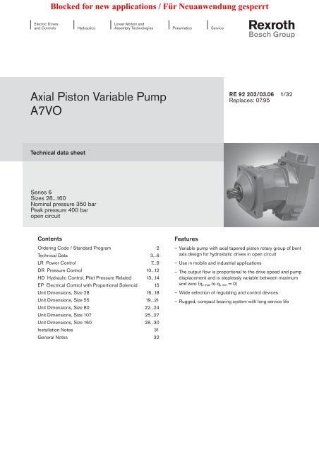
Blocked for new applications / Für Neuanwendung gesperrtElectric Drivesand ControlsHydraulicsLinear Motion andAssembly TechnologiesPneumaticsService<strong>Axial</strong> <strong>Piston</strong> <strong>Variable</strong> <strong>Pump</strong><strong>A7VO</strong>RE 92 202/03.06 1/32Replaces: 07.95Technical data sheetSeries 6Sizes 28...160Nominal pressure 350 barPeak pressure 400 baropen circuitContentsOrdering Code / Standard Program 2Technical Data 3...6LR Power Control 7...9DR Pressure Control 10...12HD Hydraulic Control, Pilot Pressure Related 13...14EP Electrical Control with Proportional Solenoid 15Unit Dimensions, Size 28 16...18Unit Dimensions, Size 55 19...21Unit Dimensions, Size 80 22...24Unit Dimensions, Size 107 25...27Unit Dimensions, Size 160 28...30Installation Notes 31General Notes 32Features– <strong>Variable</strong> pump with axial tapered piston rotary group of bentaxis design for hydrostatic drives in open circuit– Use in mobile and industrial applications– The output flow is proportional to the drive speed and pumpdisplacement and is steplessly variable between maximumand zero (q v max to q v min = 0)– Wide selection of regulating and control devices– Rugged, compact bearing system with long service life
Blocked for new applications / Für Neuanwendung gesperrt2/32 Bosch Rexroth AG <strong>A7VO</strong> RE 92 202/03.06Ordering Code / Standard ProgramA7V O / 63 – B 0101 02 03 04 05 06 07 08 09 10<strong>Axial</strong> piston unit01 Bent axis design, variable, nominal pressure 350 bar, peak pressure 400 bar <strong>A7VO</strong>peration mode02 <strong>Pump</strong>, open circuits OSize03 ≈ Displacement V g max in cm 3 28 55 80 107 160see RE 92203 250 355 500Control device 28 55 80 107 160Power controlwith pressure cut-offwith pressure cut-off and stroke limiter negative characteristic Δp = 25 bar – LRDH1LRLRD04with stroke limiter negative characteristic Δp = 25 bar – LRH1Pressure controlDRremote controlledDRGwith load sensing – DRSHydraulic control, pilot pressure related Δp = 10 bar HD1for pressure cut-off, remote controlled Δp = 10 bar HD1Gpilot pressure related Δp = 25 bar HD2for pressure cut-off, remote controlled Δp = 25 bar HD2GElectrical control, with proportional solenoidfor pressure cut-off, remote controlledEPEPGSeries 28 55 80 107 16005 Series 6, Index 3 63Direction of rotation 28...160Viewed on shaft end clockwise R06counter-clockwiseLSeals 28 55 80 107 16007 NBR (nitril-caoutchouc), shaft seal in FKM (fluor-caoutchouc) N08Shaft end 28 55 80 107 160Splined shaft, DIN 5480 ZParallel keyed shaft, DIN 6885Mounting flange 28 55 80 107 16009 4-hole – ISO 3019-2 BService line ports 28 55 80 107 16010 SAE pressure port, rear (metric fastening thread) 01SAE suction port, rear (metric fastening thread)P= preferred program
Blocked for new applications / Für Neuanwendung gesperrtRE 92 202/03.06 <strong>A7VO</strong> Bosch Rexroth AG 3/32Technical DataHydraulic fluidBefore starting project planning, please refer to our datasheets RE 90220 (mineral fluid), RE 90221 (environmentallyacceptable press ure fluids) and RE 90223 (HF pressurefluids) for detailed information regarding the choice of pressurefluids and conditions of use.The <strong>A7VO</strong> variable pump is not suitable for use with HFA. IfHFB, HFC and HFD or environmentally acceptable pressurefluids are being used, the limitations regarding technical dataand seals mentioned in RE 90221 and RE 90223 must beobserved.When ordering please indicate the used hydraulic fluid.Viscosity rangeWe recommend that a viscosity (at operating temperature) foroptimum efficiency and service life purposes ofν opt = optimum viscosity 16...36 mm 2 /sbe chosen, taken the tank temperature (open circuits) intoaccount.Limits of viscosity rangeThe following values apply in extreme cases:ν min = 5 mm 2 /sshort term (t < 3 min) at max. permitted temperaturet max = +115°C.ν max = 1600mm 2 /s,short term (t < 3 min) with cold start (p < 30 bar, n ≤ 1000 rpm,t min = -40°C).Note that the maximum hydraulic fluid temperature of 115°Cmust not be exceeded locally either (e.g. bearing area). Thetemperature in the bearing area is - depending on pressureand speed-up to 12 K higher than the average leakage fluidtemperature.Special measures are necessary at temperatures between-40°C and -25°C. Please contact us.See RE 90300-03-B for detailed information about use at lowtemperatures.Selection diagram-40° -20°16001000600400vis co si ty ν in mm 2 /s200100604020100° 20° 40° 60° 80° 100°160055-40° -25° -10° 0° 10° 30° 50° 70° 90° 115°tem pe ra ture t in °Ct min = -40°CVG 22VG 32VG 46VG 68VG 100hydraulic fluid temperature range3616t max = +115°CDetails regarding the choice of hydraulic fluidThe correct selection of hydraulic fluid requires knowledge ofthe operating temperature in relation to the ambient temperature,in an open circuit the tank temperature.The hydraulic fluid should be selected so that within theoperating temperature range, the operating viscosity lies withinthe optimum range (ν opt ) (see shaded section of the selectiondiagram). We recommend that the highest possible viscosityrange should be chosen in each case.Example: At an ambient temperature of X° C an operating temperatureof 60° C is set in the circuit. In the optimum viscosityrange (ν opt ; shaded area) this corresponds to the viscosityclasses VG 46 or VG 68; to be selected: VG 68.Please note: The leakage fluid temperature, which is affectedby pressure and rotational speed, is always higher than thetank temperature. At no point in the system may the temperaturebe higher than 115°C.If this cannot be achieved due to unusual operating parametersor high ambient temperatures, we recommend to apply bearingflushing at port U.FiltrationThe finer the filtration, the cleaner the fluid and the longertheservice life of the axial piston unit.To ensure proper function of the axial piston unit, the hydraulicfluid must have a cleanliness level of at least20/18/15 according to ISO 4406.At very high hydraulic fluid temperatures (90°C to max. 115°C),a cleanliness level of at least19/17/14 according to ISO 4406 is required.Please contact us if these cleanliness leveles cannot be achieved.
Blocked for new applications / Für Neuanwendung gesperrt4/32 Bosch Rexroth AG <strong>A7VO</strong> RE 92 202/03.06Technical DataOperating pressure rangeInletPressure at port SThe minimum inlet pressure depends on the speed. The followinglimits may not be exceeded.p abs min _________________________________________ 0,8 barThe maximum pressure p abs max also depends on speed (seesucceeding diagram).Minimum inlet pressure at suction port S with increasedspeedIn order to avoid damage of the pump a minimum inlet pressureat the suction port must be assured. The minimum inlet pressureis related to the rotational speed and the displacement ofthe variable pump.1,52,3nn max 1Speed1,42,01,91,31,81,71,61,21,51,41,31,11,21,11,01,00,90,90,80,80,6 0,7 0,8 0,9 1,0DisplacementV gV g maxNote:– max. permissible speed n max perm. (speed limit, see page 5)– min. and max. permissible inlet pressure at port S– permissible values for the shaft seal ringOutletMaximum pressure at port A or B(pressure specifications in according to DIN 24312)no radial loading(coupling)with radial loading 1 )(pinion or belt drive)Nom. pressure p NInlet pressure pabs in barPeak pressure p max350 bar 400 bar315 bar 400 bar1) please observe the permissible radial loading, see page 6Leakage fluidThe leakage fluid chamber is connected to the suction chamber.A leakage fluid line to the tank is not required (both portsR are plugged).Exception: A leakage fluid line for discharge from port T 1 to thetank is imperatively necessary for pressure control or pressurecut-off.Shaft seal ringPermissible pressure loadThe service life of the shaft seal ring is affected by the speedof the pump and the leakage fluid pressure (max. permissibleleackage fluid pressure 6 bar abs. at reduced speed, as todiagram). Short-term (t < 5 s) pressure spikes of upto 10 bar absolute are permitted. The more frequently thepressure peaks are occurring, the shorter the service life of theshaft seal ring.It is recommended the average permanent leakage fluid pressuremust not exceed 3 bar absolute.The pressure in the case must be equal to or greater than theexternal pressure on the shaft seal ring.The pure mechanical resistance to case pressure is approximately20 bar.Perm. pressure pabs. max. (bar)654321size 107size 160size 28size 55size 800 2000 4000 6000Speed n (rpm)Temperature rangeThe FKM shaft seal ring is admissible for a case temperaturerange from -25°C to +115°C.Note:For applications below -25°C a NBR shaft seal ring is necessaryas special version (admissible temperature range -40°C to+90°C). When ordering indicate NBR shaft seal ring in cleartext.Direction of flowDirection of rotation, viewed on shaft endclockwisecounter-clockwiseS to BS to A
Blocked for new applications / Für Neuanwendung gesperrtRE 92 202/03.06 <strong>A7VO</strong> Bosch Rexroth AG 5/32Technical DataTable of values (theoretical values, ignoring η mh and η v ; values rounded)Size 28 55 80 107 160Displacement V g max cm 3 28,1 54,8 80 107 160Speed max. 1 ) at V g max n max1 rpm 3150 2500 2240 2150 1900at V g < 0,74 • V g max (see diagram, page 4) n max2 rpm 4250 3400 3000 2900 2560Speed max. 2 ) n max perm. rpm 4750 3750 3350 3200 2850Flow at n max1 and V g max q v max1 L/min 89 137 179 230 304Power at q v max1 and Δp = 350 bar P max1 kW 52 80 105 134 177Torque at V g max and Δp = 350 bar T max Nm 156 305 446 596 891Mass moment of inertia (of the rotating parts) J kgm 2 0,0042 0,0042 0,0080 0,0127 0,0253Filling capacity V L 0,5 0,75 1,2 1,5 2,4Mass (approx.) m kg 17 25 40 49 711 ) The values shown are valid for an absolute pressure (p abs ) of 1 bar at the suction port S and when operated on mineral fluid with aspecific mass of 0,88 kg/L.2 ) Maximum speed (speed limit) for an increase in the inlet pressure p abs at the suction port S and V g < V g maxDetermining the sizeFlow q v =Torque T =Power P =V g • n • η v1000V g • Δp20 • π • η mh2 π • T • n=q v • Δp60000 600 • η tL/minNmkWV g = Displacement per revolution in cm 3Δp = Differential pressure in barn = Speed in rpmη v = Volumetric efficiencyη mh = Mechanical-hydraulic efficiencyη t= Overall efficiency
Blocked for new applications / Für Neuanwendung gesperrt6/32 Bosch Rexroth AG <strong>A7VO</strong> RE 92 202/03.06Technical DataPermissible radial and axial loading on the drive shaftThe values given are maximum values and do not apply to continuous operation.Size 28 55 80 107 160Radial force, max.F q Fq max N 5696 9280 11657 13580 18062at distance afrom shaft collar aa mm 12,5 15 17,5 20 22,5Radial force/bar operating pressure 1 ) F q /bar N/bar 14,2 23,2 29,1 34 45,2<strong>Axial</strong> force, max. 2 )-+F ax max N 315 500 710 900 1120F ax+–F ax max N 315 500 710 900 1120Perm. axial force/bar operating pressure ±F ax zul. /bar N/bar 4,6 7,5 9,6 11,3 15,11) at gear drive (DIN 867) with smallest PCD of pinion D R min and V g max (D R min = 2,5 x diameter of drive shaft).Preload required/bar operating pressure (radial force) to transmit torque at V-belt drive (DIN 7753) with smallest pulley diameterD K min und V g max (D K min = 5 x diameter of drive shaft).2) max. permissible axial force when stopped or when axial piston unit working in pressureless conditionsWhen considering the permissible axial force, the force-transfer direction must be taken into account:– F ax max = increase in service life of bearings+ F ax max = reduction in service life of bearings (avoid if at all possible)Effect of radial force F q on the service life of the bearingsBy selecting a suitable force-transfer direction of F q , the stress on the bearing caused by the internal transmission forces can bereduced, thus achieving the optimum service life for the bearing. Recommended position of mating gear depending on direction ofrotation. Examples:Gear driveV-belt driveϕ opt = 45°ϕ opt = 45°ϕ opt = 70°ϕ opt = 70°Clockwisedirection of rotationPressure on port BCounter-clockwisedirection of rotationPressure on port AClockwisedirection of rotationPressure on port B
Blocked for new applications / Für Neuanwendung gesperrtRE 92 202/03.06 <strong>A7VO</strong> Bosch Rexroth AG 7/32LR Power ControlThe power control regulates the displacement of the pump dependingon the operating pressure so that a given drive poweris not exceeded at constant drive speed.p B • V g = constantp B = operating pressure; V g = displacementThe precise control with a hyperbolic control characteristic,provides an optimum utilization of available power.The operating pressure acts on a rocker via a piston. An externallyadjustable spring force counteracts this, it determines thepower setting.If the operating pressure exceeds the set spring force, thecontrol valve is actuated by the rocker, the pump swivels back(direction V g min ). The lever length at the rocker is shortenedand the operating pressure can increase at the same rate asthe displacement decreases without the drive powers beingexceeded (p B • V g = constant).In zero pressure non-running condition, the pump is swivelledto its starting position (V g max ) by means of the control spring.Setting range for start of control ______________50 – 220 barThe output power (characteristic) is influenced by the efficiencyof the pump.State in clear text in the order:– drive power P in kW– drive speed n in rpm– max. flow q V max in l/minAfter clarifying the details a power diagram can be created byour computer.Characteristic LROperating pressure pB in bar220 barSetting rangeStart of control50 barV g min Displacement V g maxCircuit diagram LRU RV g min V g maxB (A)A1X3T1S
Blocked for new applications / Für Neuanwendung gesperrt8/32 Bosch Rexroth AG <strong>A7VO</strong> RE 92 202/03.06LR Power ControlLRDPower control with pressure cut-offCharacteristic LRDPressure cut-of is a pressure control that adjusts the pump displacementback towards V g min when a preset pressure value isreached.This function overrides the power control, i.e. below the presetpressure value, the power function is effective.The pressure cut-off is preset to a specified value at the factory.Setting range for pressure cut-off ____________200 – 350 barWhen ordering, state in clear text the setting of the pressurecut-off.Note:Operating pressure pB in barSetting range350max200 min– At the start of control of the power control the max. permissiblesetting of the pressure cut-off has to be multiplied byfactor 5.Example: Start of control (power control): 50 barmax. perm. setting of pressure cut-off:50 bar • 5 = 250 bar– The version with pressure cut-off necesitates a leakage fluidline from port T 1 to the tank.With plugged leackage fluid port a permissible duration ofoperation of the pressure cut-off ≤ 2 min is resulting at t tank≤ 50°C.– Any pressure relief valve included in the circuit to limit themax. pressure must be set to a cracking pressure at least 20bar above the pressure control setting.V g minCircuit diagram LRDU RDisplacementV g minV g maxV g maxA1B (A)X3T1S
Blocked for new applications / Für Neuanwendung gesperrtRE 92 202/03.06 <strong>A7VO</strong> Bosch Rexroth AG 9/32LR Power ControlLR... Power control with stroke limiterCircuit diagram LRH1The hydraulic stroke limiter can be used to vary or limit thedisplacement of the pump continuously over the whole controlrange. The displacement is set with the pilot pressure p St (max.40 bar) applied to port X 1 .The power control overrides the hydraulic stroke limiter control,i.e. below the hyperbolic power characteristic, the displacementis controlled, by the pilot pressure. When exceeding thepower characteristic with a set flow or load pressure, the powercontrol overrides and reduces the displacement followingthe hyperbolic characteristic.URX1V g minV g maxY3B (A)A1X3A control pressure of 40 bar is required to swivel the pumpfrom its starting position V g min to V g max .The required control pressure is taken either from the operatingpressure, or from the externally applied control pressure at theY 3 port.T1STo ensure the control even at low operating pressure < 40 barthe port Y 3 must be supplied with an external control pressureof approx. 40 bar.Circuit diagram LRDH1LRH1 Hydraulic stroke limiter(negative characteristic)Control from V g max to V g minX1Y3With increasing pilot pressure the pump swivels to a smallerdisplacement.Setting range for start of control ________________ 4 – 15 barWhen ordering, state in clear text the start of control.URV g maxB (A)A1Starting position without control signal (pilot pressure): V g maxCharacteristic LRH1V g minX3T1Increase in pilot pressure (V g max – V g min ) ________Δp = 25 bar40S35Pilot pressure pSt in bar30252015104Setting range0 0,2 0,4 0,6 0,8 1,0V g min Displacement V g max
Blocked for new applications / Für Neuanwendung gesperrt10/32 Bosch Rexroth AG <strong>A7VO</strong> RE 92 202/03.06DR Pressure ControlThe pressure control keeps the pressure in a hydraulic systemconstant within its control range even under varying flow conditions.The variable pump only moves as much hydraulic fluid asis required by the actuators. If the operating pressure exceedsthe setpoint set at the integral pressure control valve, the pumpdisplacement is automatically swivelled back until the pressuredeviation is corrected.In zero pressure non-running condition, the pump is swivelledto its starting position V g max by means of the control spring.Setting range for pressure control _____________50 – 350 barWhen ordering, state in clear text the setting of the pressurecontrol.Note:– The version with pressure control DR necesitates a leakagefluid line from port T 1 to the tank.– Any pressure relief valve included in the circuit to limit themax. pressure must be set to a cracking pressure at least 20bar above the pressure control setting.Zero stroke operationThe standard pump unit is designed for intermittent constantpressure operation. Short-term operation at zero stroke (< 10min.) is permissible up to a operating pressure p max = 315 barat a tank temperature of ≤ 50°C.For long-term periods of zero stroke operation, port U shouldbe used for bearing flushing.Flushing portURSCharacteristic DROperating pressure pB in barSetting range350max50minmax. 10 barFlushing flow (recommended)Size 28 55 80 107 160q v flush (L/min) 3 4 6 8 12Temperatur of flushing fluid ≤ tank temperaturFlow q v in L/minCircuit diagram DRURB (A)V g minV g maxA1X3T1S
Blocked for new applications / Für Neuanwendung gesperrtRE 92 202/03.06 <strong>A7VO</strong> Bosch Rexroth AG 11/32DR Pressure ControlDRG Pressure control, remote controlledA sequence valve with port plate takes over the function of thepressure cut-off. The valve is mounted separate from the pump,and the simple piping length should not exceed 5 m. Highpressure is supplied from the pump to the valve via port A 1 , andthe valve control pressure is fed back to the pump via port X 3 ,causing the pump to swivel back towards V g min . Port T of thesequence valve and port T 1 of the pump must be connectedback to tank (cooler).Setting range for pressure control _____________ 50 – 315 barWhen ordering, state in clear text the setting of the pressurecontrol.Note:– Any pressure relief valve included in the circuit to limit themax. pressure must be set to a cracking pressure at least 20bar above the pressure control setting.The sequence valve and port plate must be ordered separately.Sequence valve: DZ5DP2-1X/315YMSO21(Mat.No. R900495604)Port plate: G 115/1 (Mat.No. R900424379)Characteristic DRGOperating pressure pB in barSetting range31550maxminmax. 10 barFlow q v in L/minCircuit diagram DRG(1)URB (A)PATV g minV g maxA1X3T1SPosition (1) is not included in the pump supply.
Blocked for new applications / Für Neuanwendung gesperrt12/32 Bosch Rexroth AG <strong>A7VO</strong> RE 92 202/03.06DR Pressure ControlDRSPressure control with load sensingCharacteristic DRSThe load sensing control is a flow control option that operatesas a function of the load pressure to regulate the pump displacementto match the actuator flow requirement.The flow depends here on the cross section of the externalsensing orifice (1) fitted between the pump outlet and theactuator. The flow is independent of the load pressure belowthe pressure cut-off setting and within the control range of thepump.The sensing orifice is usually a separately arranged loadsensing directional valve (control block). The position of thedirectional valve piston determines the opening cross sectionof the sensing orifice and thus the flow of the pump.The load-sensing control compares pressure before and afterthe sensing orifice and maintains the pressure drop across theorifice - and therefore the pump flow - constant as a function ofthe orifice size.If the differential pressure Δp increases, the pump is swivelledback towards V g min and, if the Δp decreases the pump isswivelling out towards V g max until the pressure drop across thesensing orifice in the valve is restored.Δp orifice = p pump – p actuatorSetting range for Δp _________________________ 14 – 25 barOperating pressure pB in barSetting range350max50minCircuit diagram DRSU RFlow q v in L/minX4B (A)V g min V g maxA1(1)max. 10 barStandard setting _________________________________18 bar(please state in clear text when ordering)The stand-by pressure in zero stroke operation (sensing orificeplugged) is slightly above the Δp setting.(1) The sensing orifice (control block) is not included in thepump supply.X3T1SPosition (1) is not included in the pump supply.
Blocked for new applications / Für Neuanwendung gesperrtRE 92 202/03.06 <strong>A7VO</strong> Bosch Rexroth AG 13/32HD Hydraulic Control, Pilot Pressure RelatedWith the pilot pressure related control the pump diplacement isadjusted in proportion to the pilot pressure applied to port X 1 .Maximum permissible pilot pressure p St max = 40 barControl from V g min to V g max .Circuit diagram HDX1Y3With increasing pilot pressure the pump swivels to a higherdisplacementSetting range for start of control _________________ 4 - 15 barWhen ordering, state in clear text the start of control.URV g minB (A)A1A control pressure of 40 bar is required to swivel the pumpfrom its starting position V g min to V g max .The required control pressure is taken either from the operatingpressure, or from the externally applied control pressure atthe Y 3 port.V g maxX3STo ensure the control even at low operating pressure < 40 barthe port Y 3 must be supplied with an external control pressureof approx. 40 bar.Characteristic HD1Increase in pilot pressure V g min to V g max ________ Δp = 10 bar4035Pilot pressure pSt in barSetting range302520151040 0,2 0,4 0,6 0,8 1,0V g min Displacement V g maxCharacteristic HD2Increase in pilot pressure V g min to V g max ________Δp = 25 bar4035Pilot pressure pSt in barSetting range302520151040 0,2 0,4 0,6 0,8 1,0V g min DisplacementV g max
Blocked for new applications / Für Neuanwendung gesperrt14/32 Bosch Rexroth AG <strong>A7VO</strong> RE 92 202/03.06HD Hydraulic Control, Pilot Pressure RelatedHD.G Hydraulic control, for pressure cut-off,remote controlledA sequence valve with port plate takes over the function of thepressure cut-off. The valve is mounted separate from the pump,and the simple piping length should not exceed 5 m. Highpressure is supplied from the pump to the valve via port A 1 .The control pressure of the pump is directed to the valve viathe port X 3 and led into the tank at port A located on the portplate of the sequence valve. In this case the pump is regulatedto V g min in case of access of the set-point pressure value.Setting range for pressure control _____________ 50 – 315 barWhen ordering, state in clear text the setting of the pressurecontrol.Note:– The port A of the sequence valve must be connected back totank (cooler).– Any pressure relief valve included in the circuit to limit themax. pressure must be set to a cracking pressure at least 20bar above the pressure control setting.The sequence valve and port plate must be ordered separately.Sequence valve: DZ5DP2-1X/315XYMSO20(Mat.No. R900490554)Port plate: G 115/1 (Mat.No. R900424379)Characteristic HD.GOperating pressure pB in barSetting range31550maxminmax. 10 barCircuit diagram HD.GURX1V g maxV g minPosition (1) is not included in the pump supply.Y3B (A)NoteThe spring centering in the pilot control unit is not asafety deviceThrough contamination in the control unit – e.g. in hydraulicfluid, wear particles, or particles out of a system – the valvespool can get stuck in an undefined position. In this case, thepump flow does not follow the command inputs of the machineoperator anymore.– Make sure that a proper emergency shut down functioncan bring the driven machine movements to a safe positionimmediately (e.g. stop).– Adhere to the speci fi ed cleanliness level 20/18/15 (90 °C) to ISO 4406.A1X3S(1)PXAFlow q v in L/min
Blocked for new applications / Für Neuanwendung gesperrtRE 92 202/03.06 <strong>A7VO</strong> Bosch Rexroth AG 15/32EP Electrical Control with Proportional SolenoidWith the electrical control with proportional solenoid, the pumpdisplacement is adjusted proportionally to the solenoid current,resulting in a magnetic control force, acting directly onto thecontrol spool that pilots the pump control piston.Control from V g min to V g maxWith increasing control current the pump swivels to a higherdisplacement.A control pressure of 40 bar is required to swivel the pumpfrom its starting position V g min to V g max .The required control pressure is taken either from the operatingpressure, or from the externally applied control pressure at theY 3 port.To ensure the control even at low operating pressure < 40 barthe port Y 3 must be supplied with a external control pressure ofapprox. 40 bar.Note:– Install pump with EP control in the fluid tank only when usingmineral hydraulic fluids and an fluid temperature in the tankof max. 80° C.To control the proportional solenoids the following electronicamplifi er and controller are available (also as to the Internetunder www.boschrexroth.com/mobile-electronic):– BODAS controller RC (RE 95200)and application software– Analog amplifier RA (RE 95230)By using an proportional amplifier control of swivel time is alsopossible.Characteristic EPControl current I in mA800700600500400300200100Circuit diagram EPUR0 0,2 0,4 0,6 0,8 1,0V g min Displacement V g maxV g maxV g minY3B (A)A1X3STechnical data of solenoidsEPVoltage 24 VDC (±20%)Control currentStart of control at V g min200 mAEnd of control at V g max600 mALimiting current0,68 ANominal resistance (at 20°C)19,5 ΩDither frequency100 HzDuty cycle 100%Type of protection (HIRSCHMANN)IP65to DIN EN 60529EP.Gsee HD.GElectrical control, for pressure cut-off,remote controlledNoteThe spring centering in the pilot control unit is not asafety deviceThrough contamination in the control unit – e.g. in hydraulicfluid, wear particles, or particles out of a system – the valvespool can get stuck in an undefined position. In this case, thepump flow does not follow the command inputs of the machineoperator anymore.– Make sure that a proper emergency shut down functioncan bring the driven machine movements to a safe positionimmediately (e.g. stop).– Adhere to the specified cleanliness level 20/18/15 (90 °C) to ISO 4406.
Blocked for new applications / Für Neuanwendung gesperrt16/32 Bosch Rexroth AG <strong>A7VO</strong> RE 92 202/03.06Unit Dimensions, Size 28LR Power controlNote: All control versions are shown with clockwise direction of rotation.Before finalizing your design, please requestapproved installation drawing. Dimensions in mm.2616UR215209 (A1)207T 1A 145°45°X 392ø100 -0.022ø6213.4 max25FlangeISO 3019-27R12° 30'198209 (X3)29119182033Y118ø125ø11118View Yclockwise rotationView Ycounter-clockwise rotation7149796052T 1A 1X 3X 3T 1SLRA 1SLR50.8ø1924ø3869.9AB23.849108.535.7
Blocked for new applications / Für Neuanwendung gesperrtRE 92 202/03.06 <strong>A7VO</strong> Bosch Rexroth AG 17/32Unit Dimensions, Size 28Shaft endsBefore finalizing your design, please requestapproved installation drawing. Dimensions in mm.Z Splined shaft DIN 5480W25x1,25x30x18x9g196PParallel keyed shaftDIN 6885, AS8x7x40196M8x1.25 1 ) 2 )ø354315ø25 +0.002+0.015M8x1.25 1 ) 2 )28ø3550PortsA, B Service line ports (high pressure series) SAE J518 3/4 infastening thread DIN 13 M10x1,5; 17 deep 2 )S Suction port (standard series) SAE J518 1 1/2 infastening thread DIN 13 M12x1,75; 20 deep 2 )U Bearing flushing (plugged) DIN 3852 M16x1,5; 12 deep 100 Nm 2 )R Air bleed (plugged) DIN 3852 M18x1,5; 12 deep 140 Nm 2 )A 1 High pressure (plugged) DIN 3852 M12x1,5; 12 deep 50 Nm 2 )T 1 Pilot fluid drain (plugged, only DR, ..D.. open) DIN 3852 M12x1,5; 12 deep 50 Nm 2 )X 3 Override (plugged) DIN 3852 M12x1,5; 12 deep 50 Nm 2 )Y 3 External control pressure (plugged) DIN 3852 M14x1,5; 12 deep 80 Nm 2 )X 1 Pilot pressure DIN 3852 M14x1,5; 12 deep 80 Nm 2 )1 ) centering bore according to DIN 332 (thread according to DIN 13)2 ) please observe the general notes for the max. tightening torques on page 32
Blocked for new applications / Für Neuanwendung gesperrt18/32 Bosch Rexroth AG <strong>A7VO</strong> RE 92 202/03.06Unit Dimensions, Size 28LRDPower control with pressure cut-offBefore finalizing your design, please requestapproved installation drawing. Dimensions in mm.D236LR124108.5DR/DRGPressure control, remote controlledDR236DRGHD1/HD1G/HD2/HD2GHydraulic control for pressure cut-off, remote controlled216EP/EPGElectrical control for pressure cut-off, remote controlled21676 (X3)78 (A1)A 1X 3Y 3X 3A 1X 1Y 315392 (DRG)132 (DR)7717019976 (X3)78 (A1)A 1X 3 X 3A 1Y 3Y 3153274 774.5 1549155 (X1)159 (Y3)187 (A1)188 (X3)X 149 15159 (Y3)187 (A1)188 (X3)
Blocked for new applications / Für Neuanwendung gesperrtRE 92 202/03.06 <strong>A7VO</strong> Bosch Rexroth AG 19/32Unit Dimensions, Size 55LR Power controlNote: All control versions are shown with clockwise direction of rotationBefore finalizing your design, please requestapproved installation drawing. Dimensions in mm.3220U262241(T1)232RT 1A 114045°45°ø125 -0.025ø7012°30'3512X 33536Yø160ø13.515014.6 max31FlangeISO 3019-27.5R241 (A1)242 (X3)142150LRView Ycounter-clockwise rotationView Yclockwise rotation76 9057 6212LRT 1 A 1 A 1T 1SX 3 X 3 S50.8ø193277.8ø49AB23.842.949100
Blocked for new applications / Für Neuanwendung gesperrt20/32 Bosch Rexroth AG <strong>A7VO</strong> RE 92 202/03.06Unit Dimensions, Size 55Shaft endsBefore finalizing your design, please requestapproved installation drawing. Dimensions in mm.Z Splined shaft DIN 5480W30x2x30x14x9g289.5PParallel keyed shaftDIN 6885, AS8x7x50289.5ø45M12x1.75 1 ) 2 )ø45835+0.015ø30 +0.002M12x1.75 1 ) 2 )3360PortsA, B Service line ports (high pressure series) SAE J518 3/4 inFastening thread DIN 13 M10x1,5; 17 deep 2 )S Suction port (standard series) SAE J518 2 inFastening thread DIN 13 M12x1,75; 20 deep 2 )U Bearing flushing (plugged) DIN 3852 M18x1,5; 12 deep 140 Nm 2 )R Air bleed (plugged) DIN 3852 M18x1,5; 12 deep 140 Nm 2 )A 1 High pressure (plugged) DIN 3852 M14x1,5; 12 deep 80 Nm 2 )T 1 Pilot fluid drain (plugged, only DR, ..D.. open) DIN 3852 M12x1,5; 12 deep 50 Nm 2 )X 3 Override (plugged) DIN 3852 M14x1,5; 12 deep 80 Nm 2 )Y 3 External control pressure (plugged) DIN 3852 M14x1,5; 12 deep 80 Nm 2 )X 1 Pilot pressure DIN 3852 M14x1,5; 12 deep 80 Nm 2 )X 4 Load pressure DIN 3852 M14x1,5; 12 deep 80 Nm 2 )1 ) centering bore according to DIN 332 (thread according to DIN 13)2 ) please observe the general notes for the max. tightening torques on page 32
Blocked for new applications / Für Neuanwendung gesperrtRE 92 202/03.06 <strong>A7VO</strong> Bosch Rexroth AG 21/32Unit Dimensions, Size 55LRDPower control with pressure cut-offDLR128Before finalizing your design, please requestapproved installation drawing. Dimensions in mm.LRDH1Power control with pressure cut-off, stroke limiterX 1Y 312DLR262257 (X1)252 (Y3)X 1Y 3105127170119DR/DRGPressure control, remote controlled119DRSPressure control with load sensingDRDRGX 46 300DR238X 4114 (DRG)135 (DR)141151HD1/HD1G/HD2/HD2GHydraulic control for pressure cut-off, remote controlled256EP/EPGElectrical control for pressure cut-off, remote controlled25682101X 3A 1X 3Y A 3 1170192221100X 3A 1X 3Y A 3 182101170296 10012 1257X 1X 1186 (X1)190 (Y3)209 (A1)221 (X3)Y 312 1257190 (Y3)209 (A1)221 (X3)Y 3
Blocked for new applications / Für Neuanwendung gesperrt22/32 Bosch Rexroth AG <strong>A7VO</strong> RE 92 202/03.06Unit Dimensions, Size 80Before finalizing your design, please requestapproved installation drawing. Dimensions in mm.LR Power controlNote: All control versions are shown with clockwise direction of rotation287270 (T1)253233245°45°URA 1X 3144ø13.5ø140 -0.025ø8312°30'37173840Yø1801651571657.5R14.6 maxFlangeISO 3019-231265 (X3)270 (A1)8010262227064T 1 A 1 A 1T 1SX 3X 3T 127.8View Yclockwise rotationLRView Ycounter-clockwise rotationLRS57.2ø2534ø6288.9AB50.857111
Blocked for new applications / Für Neuanwendung gesperrtRE 92 202/03.06 <strong>A7VO</strong> Bosch Rexroth AG 23/32Unit Dimensions, Size 80Shaft endsBefore finalizing your design, please requestapproved installation drawing. Dimensions in mm.Z Splined shaft DIN 5480W35x2x30x16x9g289.5PParallel keyed shaftDIN 6885, AS10x8x56289.5ø50M12x1.75 1 ) 2 )38ø50840+0.018ø35 +0.002M12x1.75 1 ) 2 )70PortsA, B Service line ports (high pressure series) SAE J518 1 inFastening thread DIN 13 M12x1,75; 17 deep 2 )S Suction port (standard series) SAE J518 2 1/2 inFastening thread DIN 13 M12x1,75; 17 deep 2 )U Bearing flushing (plugged) DIN 3852 M18x1,5; 12 deep 140 Nm 2 )R Air bleed (plugged) DIN 3852 M18x1,5; 12 deep 140 Nm 2 )A 1 High pressure (plugged) DIN 3852 M16x1,5; 12 deep 100 Nm 2 )T 1 Pilot fluid drain (plugged, only DR, ..D.. open) DIN 3852 M12x1,5; 12 deep 50 Nm 2 )X 3 Override (plugged) DIN 3852 M16x1,5; 12 deep 100 Nm 2 )Y 3 External control pressure (plugged) DIN 3852 M14x1,5; 12 deep 80 Nm 2 )X 1 Pilot pressure DIN 3852 M14x1,5; 12 deep 80 Nm 2 )X 4 Load pressure DIN 3852 M14x1,5; 12 deep 80 Nm 2 )1 ) centering bore according to DIN 332 (thread according to DIN 13)2 ) please observe the general notes for the max. tightening torques on page 32
Blocked for new applications / Für Neuanwendung gesperrt24/32 Bosch Rexroth AG <strong>A7VO</strong> RE 92 202/03.06Unit Dimensions, Size 80LRDPower control with pressure cut-offDBefore finalizing your design, please requestapproved installation drawing. Dimensions in mm.LRDH1Power control with pressure cut-off, stroke limiter29014 284 (X1)X279 (Y3)1 DX 1Y 3Y 3LR132LR116138182130130DR/DRGPressure control, remote controlledDRDRGDRSPressure control with load sensing6327X 4 DR 265X 4125 (DRG)139 (DR)151161HD1/HD1G/HD2/HD2GHydraulic control for pressure cut-off, remote controlled287EP/EPGElectrical control for pressure cut-off, remote controlled287X 3A 1X 3Y 3 A 1X 192113187209240 11492113187315 114X 3A 1X 3Y 3 A 122 1462207 (X1)212 (Y3)237 (A1)241 (X3)Y 3X 122 1462212 (Y3)237 (A1)241 (X3)Y 3
Blocked for new applications / Für Neuanwendung gesperrtRE 92 202/03.06 <strong>A7VO</strong> Bosch Rexroth AG 25/32Unit Dimensions, Size 107LR Power controlNote: All control versions are shown with clockwise direction of rotationBefore finalizing your design, please requestapproved installation drawing. Dimensions in mm.2540UR307286 (T1)27245°45°ø160 -0.025ø9012°30'41A 1X 318Y1703746150ø200ø17.519014.6 max39FlangeISO 3019-27.5R284 (X3)289 (A1)190View Yclockwise rotationLRView Ycounter-clockwise rotation8810570 7422 72LRT 1SA 1X 3A 1X 3T 1S57.2ø2536ø6288.9AB27.850.855115
Blocked for new applications / Für Neuanwendung gesperrt26/32 Bosch Rexroth AG <strong>A7VO</strong> RE 92 202/03.06Unit Dimensions, Size 107Shaft endsBefore finalizing your design, please requestapproved installation drawing. Dimensions in mm.Z Splined shaft DIN 5480W40x2x30x18x9g289.5PParallel keyed shaftDIN 6885, AS12x8x63289.5M12x1.75 1 ) 2 )ø6043ø60845+0.018ø40 +0.002M12x1.75 1 ) 2 )80PortsA, B Service line ports (high pressure series) SAE J518 1 inFastening thread DIN 13 M12x1,75; 17 deep 2 )S Suction port (standard series) SAE J518 2 1/2 inFastening thread DIN 13 M12x1,75; 17 deep 2 )U Bearing flushing (plugged) DIN 3852 M18x1,5; 12 deep 140 Nm 2 )R Air bleed (plugged) DIN 3852 M18x1,5; 12 deep 140 Nm 2 )A 1 High pressure (plugged) DIN 3852 M16x1,5; 12 deep 100 Nm 2 )T 1 Pilot fluid drain (plugged, only DR, ..D.. open) DIN 3852 M12x1,5; 12 deep 50 Nm 2 )X 3 Override (plugged) DIN 3852 M16x1,5; 12 deep 100 Nm 2 )Y 3 External control pressure (plugged) DIN 3852 M14x1,5; 12 deep 80 Nm 2 )X 1 Pilot pressure DIN 3852 M14x1,5; 12 deep 80 Nm 2 )X 4 Load pressure DIN 3852 M14x1,5; 12 deep 80 Nm 2 )1 ) centering bore according to DIN 332 (thread according to DIN 13)2 ) please observe the general notes for the max. tightening torques on page 32
Blocked for new applications / Für Neuanwendung gesperrtRE 92 202/03.06 <strong>A7VO</strong> Bosch Rexroth AG 27/32Unit Dimensions, Size 107LRDPower control with pressure cut-offDLR138Before finalizing your design, please requestapproved installation drawing. Dimensions in mm.LRDH1Power control with pressure cut-off, stroke limiterX 1Y 318DLR309300 (X1)295 (Y3)X 1Y 3122144189134134DR/DRGPressure control, remote controlledDRSPressure control with load sensingDRDRGX 4DR352290X4154167132 (DRG)145 (DR)HD1/HD1G/HD2/HD2GHydraulic control for pressure cut-off, remote controlled306EP/EPGElectrical control for pressure cut-off, remote controlled306100119X 3A 1X 3Y 3 A 1X 1199221122252X 3A 1X 3Y 3 A 1100119199327 12222 1870220 (X1)225 (Y3)254 (A1)259 (X3)Y 3X 122 1870225 (Y3)254 (A1)259 (X3)Y 3
Blocked for new applications / Für Neuanwendung gesperrt28/32 Bosch Rexroth AG <strong>A7VO</strong> RE 92 202/03.06Unit Dimensions, Size 160Before finalizing your design, please requestapproved installation drawing. Dimensions in mm.LR Power controlNote: All control versions are shown with clockwise direction of rotation349328 (T1)3102840URT 1A 1X 316045°45°ø180 -0.025ø10012°30'47275546Yø224ø17.519321014.9 max397.5R210FlangeISO 3019-2327 (X3)331 (A1)View Yclockwise rotation100 126LRView Ycounter-clockwise rotation782284LRT 1 A 1 A 1T 1SX 3 X 3 S66.7ø3240ø75106.4AB31.86661.9
Blocked for new applications / Für Neuanwendung gesperrtRE 92 202/03.06 <strong>A7VO</strong> Bosch Rexroth AG 29/32Unit Dimensions, Size 160Shaft endsBefore finalizing your design, please requestapproved installation drawing. Dimensions in mm.Z Splined shaft DIN 5480W45x2x30x21x9g3612PParallel keyed shaftDIN 6885, AS14x9x703612ø70M16x2 1 ) 2 )48.5ø70850+0.018ø45 +0.002M16x2 1 ) 2 )90PortsA, B Service line ports (high pressure series) SAE J518 1 1/4 inFastening thread DIN 13 M14x1,5; 19 deep 2 )S Suction port (standard series) SAE J518 3 inFastening thread DIN 13 M16x1,5; 24 deep 2 )U Bearing flushing (plugged) DIN 3852 M22x1,5; 14 deep 210 Nm 2 )R Air bleed (plugged) DIN 3852 M26x1,5; 16 deep 230 Nm 2 )A 1 High pressure (plugged) DIN 3852 M16x1,5; 12 deep 100 Nm 2 )T 1 Pilot fluid drain (plugged, only DR, ..D.. open) DIN 3852 M12x1,5; 12 deep 50 Nm 2 )X 3 Override (plugged) DIN 3852 M16x1,5; 12 deep 100 Nm 2 )Y 3 External control pressure (plugged) DIN 3852 M14x1,5; 12 deep 80 Nm 2 )X 1 Pilot pressure DIN 3852 M14x1,5; 12 deep 80 Nm 2 )X 4 Load pressure DIN 3852 M14x1,5; 12 deep 80 Nm 2 )1 ) centering bore according to DIN 332 (thread according to DIN 13)2 ) please observe the general notes for the max. tightening torques on page 32
Blocked for new applications / Für Neuanwendung gesperrt30/32 Bosch Rexroth AG <strong>A7VO</strong> RE 92 202/03.06Unit Dimensions, Size 160LRDPower control with pressure cut-offDBefore finalizing your design, please requestapproved installation drawing. Dimensions in mm.LRDH1Power control with pressure cut-off, stroke limiter35119340 (X1)334 (Y3)X 1 DX 1Y 3Y 3LR150LR140DR/DRGPressure control, remote controlledDRSPressure control with load sensing392X 4DR 329X 4150 (DRG)155 (DR)172185162207145145DRDRGHD1/HD1G/HD2/HD2GHydraulic control for pressure cut-off, remote controlled348EP/EPGElectrical control for pressure cut-off, remote controlled348120139X 3A 1XY 33 AX 1122 1978249 (X1)253 (Y3)290 (A1)294 (X3)Y 3X 1137225248278120139X 3A 1X 3Y 3 A 122 1978253 (Y3)290 (A1)294 (X3)Y 3225353 137
Blocked for new applications / Für Neuanwendung gesperrtRE 92 202/03.06 <strong>A7VO</strong> Bosch Rexroth AG 31/32Installation NotesGeneralDuring commissioning and operation, the axial piston unit must be filled with hydraulic fluid and air bled. This is also to be observedfollowing a relatively long standstill as the system may empty via the hydraulic lines.The leakage fluid chamber is internally connected to the suction chamber. A leakage fluid line to the tank is not required.Exception: Operation with pressure control or pressure cut-off.In all operating states, the suction line must flow into the tank below the minimum fluid level.The minimum suction pressure at port S must not fall below 0,8 bar absolute.Installation positionAs to the examples mentioned below. Further installation positions are possible upon consultation.Installation below the tank (standard)<strong>Pump</strong> below minimum fluid level in tank.Recommendation installation position: 1 and 2.1 2UR 1 R 2SSUR 2 R 1R 13 4SR 2UR 1UR 2SInstallationpositionAir bleedFilling1 R 1 S2 R 2 S3 R 1, R 2 S4 U S
Blocked for new applications / Für Neuanwendung gesperrt32/32 Bosch Rexroth AG <strong>A7VO</strong> RE 92 202/03.06General Notes– The <strong>A7VO</strong> pump is designed to be used in open circuits.– Project planning, assembly and commissioning of the pump require the involvement of trained personnel.– The working and functional ports are only designed to accommodate hydraulic piping.– There is a danger of burns from the pump and especially the solenoids during and shortly after operation. Suitable safetyprecautions, e.g. protective clothing plan.– The characteristic curve may shift depending on the operating status (operating pressure, fluid temperature) of the pump.– Tightening torques:- The tightening torques specified in this data sheet are maximum values and may not be exceeded(maximum value for screw thread).Manufacturer specifications for the max. permissible tightening torques of the used fittings must be observed!- For DIN 13 fastening screws we recommend checking the tightening torque individually according to VDI 2230 Edition 2003.– The data and information contained herein must be adhered to.Bosch Rexroth AGHydraulicsProduct Segment <strong>Axial</strong> <strong>Piston</strong> UnitsElchingen PlantGlockeraustrasse 289275 Elchingen, GermanyPhone +49 (0) 73 08 82-0Facsimile +49 (0) 73 08 72 74info.brm-ak@boschrexroth.dewww.boschrexroth.com/axial-piston-pumps© This document, as well as the data, specifications and other informationset forth in it, are the exclusive property of Bosch Rexroth AG. It may not bereproduced or given to third parties without its consent.The data specified above only serve to describe the product. No statementsconcerning a certain condition or suitability for a certain application can bederived from our information. The information given does not release the userfrom the obligation of own judgment and verification. It must be remembered thatour products are subject to a natural process of wear and aging.Subject to change.