Download manual
Download manual
Download manual
- No tags were found...

Create successful ePaper yourself
Turn your PDF publications into a flip-book with our unique Google optimized e-Paper software.
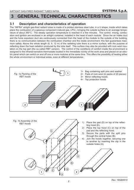
AIRTIGHT GAS-FIRED RADIANT TUBES INFRA3 GENERAL TECHNICAL CHARACTERISTICSSYSTEMA S.p.A.3.1 Description and characteristics of operationThe “INFRA” airtight gas-fired radiant tubes is made of a pickled stainless steel tube, in a U shape, inside which takesplace the combustion of a gaseous component (natural gas, LPG.), bringing the outside surface to an average temperatureof about 350°C. The steady operation temperature is reached in a few minutes. The control, mixing, combustionand ignition are enclosed in an airtight container, installed in the head of each module. Since the air intake ductand the fume expulsion duct are continuously connected from the head of the module to the outside of the building,there is no communication between the combustion chamber and the inside environment; this fact guarantees maximumsafety. Above the whole length (6, 9, 12 m) of the radiating tube there is a mirror surface, with the purpose ofreflecting down the heat radiation produced by the tube itself. This surface may also be provided with rock wool insulationon the top part (the so-called RBT version). The control of the conditions of comfort inside the environment isassigned to the infrared-sensitive thermostats located in the immediate vicinity of the work area and placed on an electricpanel which can switch on and off one or more modules at the same time. This offers the possibility of heating eitherthe whole environment or individual areas, even at different temperatures.Fig. 1a Packing of theRBT hoods11= Bag containing split pins and washer2= Pads of rock wool (in packs of 20 pieces)3= Mirror reflecting hoods4= Top protection hoods23 4Fig. 1b Assembly of theRBT hoodsC1) Place the pad (D) on top of the reflectinghood (E).2) Place the top hood (C) on top of thepad and the reflecting hood.3) Secure the parts with the split pinsthrough the central holes (B).4) Join the hoods together, securing oneto another by inserting the clip in theoutside holes (A).DAB1EAB27Rev. 18GB0610