Download manual
Download manual
Download manual
- No tags were found...

Create successful ePaper yourself
Turn your PDF publications into a flip-book with our unique Google optimized e-Paper software.
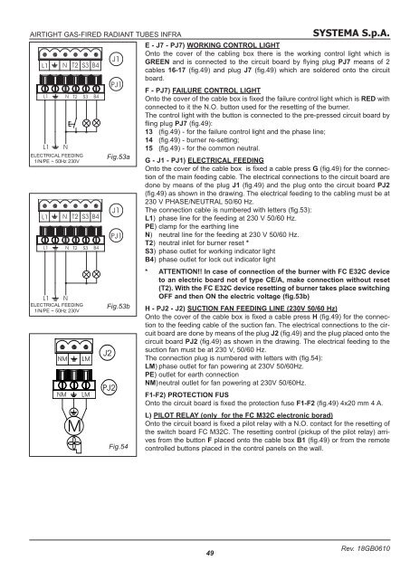
SYSTEMA S.p.A.AIRTIGHT GAS-FIRED RADIANT TUBES INFRAE - J7 - PJ7) WORKING CONTROL LIGHTOnto the cover of the cabling box there is the working control light which isGREEN and is connected to the circuit board by flying plug PJ7 means of 2cables 16-17 (fig.49) and plug J7 (fig.49) which are soldered onto the circuitboard.F - PJ7) FAILURE CONTROL LIGHTOnto the cover of the cable box is fixed the failure control light which is RED withconnected to it the N.O. button used for the resetting of the burner.The control light with the button is connected to the pre-pressed circuit board byfling plug PJ7 (fig.49):13 (fig.49) - for the failure control light and the phase line;14 (fig.49) - burner re-setting;15 (fig.49) - for the common neutral.ELECTRICAL FEEDING1/N/PE ~ 50Hz 230VFig.53aG - J1 - PJ1) ELECTRICAL FEEDINGOnto the cover of the cable box is fixed a cable press G (fig.49) for the connectionof the main feeding cable. The electrical connections to the circuit board aredone by means of the plug J1 (fig.49) and the plug onto the circuit board PJ2(fig.49) as shown in the drawing. The electrical feeding to the cabling must be at230 V PHASE/NEUTRAL 50/60 Hz.The connection cable is numbered with letters (fig.53):L1) phase line for the feeding at 230 V 50/60 Hz.PE) clamp for the earthing lineN) neutral line for the feeding at 230 V 50/60 Hz.T2) neutral inlet for burner reset *S3) phase outlet for working indicator lightB4) phase outlet for lock out indicator light* ATTENTION!! In case of connection of the burner with FC E32C deviceto an electric board not of type CE/A, make connection without reset(T2). With the FC E32C device resetting of burner takes place switchingOFF and then ON the electric voltage (fig.53b)ELECTRICAL FEEDING1/N/PE ~ 50Hz 230VFig.53bFig.54H - PJ2 - J2) SUCTION FAN FEEDING LINE (230V 50/60 Hz)Onto the cover of the cable box is fixed a cable press H (fig.49) for the connectionto the feeding cable of the suction fan. The electrical connections to the circuitboard are done by means of the plug J2 (fig.49) and the plug placed onto thecircuit board PJ2 (fig.49) as shown in the drawing. The electrical feeding to thesuction fan must be at 230 V, 50/60 Hz.The connection plug is numbered with letters with (fig.54):LM) phase outlet for fan powering at 230V 50/60Hz.PE) outlet for earth connectionNM)neutral outlet for fan powering at 230V 50/60Hz.F1-F2) PROTECTION FUSOnto the circuit board is fixed the protection fuse F1-F2 (fig.49) 4x20 mm 4 A.L) PILOT RELAY (only for the FC M32C electronic borad)Onto the circuit board is fixed a pilot relay with a N.O. contact for the resetting ofthe switch board FC M32C. The resetting control (pickup of the pilot relay) arrivesfrom the button F placed onto the cable box B1 (fig.49) or from the remotecontrolled buttons placed in the control panels on the wall.49Rev. 18GB0610