Download manual
Download manual
Download manual
- No tags were found...

Create successful ePaper yourself
Turn your PDF publications into a flip-book with our unique Google optimized e-Paper software.
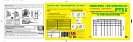
AIRTIGHT GAS-FIRED RADIANT TUBES INFRA8 ELECTRICAL SYSTEMSYSTEMA S.p.A.8.1 Connection diagram for CE/A type control panelsTo connect the control panels for series CE burners, refer to the wiring diagram shown in fig. 45 and fig. 46.In particular:a) Use an electric cable composed of 6 leads necessary for the phase, neutral, earth, appliance reset, operating warninglight and block warning light.b) Ensure that the appliance is correctly earthed and respect the phase and neutral connection, otherwise seriesCE/A control panels will be subject to breakdown.c) Position the environment thermostat at a height of 1.50÷1.80 mt above ground and in an area where the globothermostatprobe can be within “sight” of the radiating pipes; only in this way can the probe receive the infraredradiation emitted by the pipes and thus control the local comfort conditions (see fig. 44).ELECTRIC CONTROL PANELWITH GLOBOTHERMOSTAT PROBEFig. 44 Positioning of the globothermostat probe43Rev. 18GB0610