Download manual
Download manual
Download manual
- No tags were found...

Create successful ePaper yourself
Turn your PDF publications into a flip-book with our unique Google optimized e-Paper software.
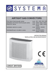
AIRTIGHT GAS-FIRED RADIANT TUBESINFRA 6B - 9B - 12BGREAT BRITAININSTRUCTION MANUAL“INSTALLATION, USE AND MAINTENANCE”
SYSTEMA S.p.A.AIRTIGHT GAS-FIRED RADIANT TUBES INFRA IMPORTANT: Read this <strong>manual</strong> carefully before starting up the plant. To improve the product, Systema reservesthe right to alter the content whenever it wishes, without prior notice.Via San Martino 17/23S. GIUSTINA IN COLLE (PD)loc. Fratte Fontane BianchePADOVA - ITALYTel 0039 0499355663(8 linee r.a.)Fax 0039 0499355699E-mail: systema@systema.ittechnical informationshttp://www.systema.itcommercial informationsRev. 18GB06102
AIRTIGHT GAS-FIRED RADIANT TUBES INFRASYSTEMA S.p.A.1 GENERAL RULES . . . . . . . . . . . . . . . . . . . . . . . . . . . . . . . . . . . . . . . . . . . .52 PACKING . . . . . . . . . . . . . . . . . . . . . . . . . . . . . . . . . . . . . . . . . . . . . . . . . . .52.1 Packing list . . . . . . . . . . . . . . . . . . . . . . . . . . . . . . . . . . . . . . . . . . . . . . . . . . . . . . . . . . .53 GENERAL TECHNICAL CHARACTERISTICS . . . . . . . . . . . . . . . . . . . . . .73.1 Description and characteristics of operation . . . . . . . . . . . . . . . . . . . . . . . . . . . . . . .73.2 Technical characteristics . . . . . . . . . . . . . . . . . . . . . . . . . . . . . . . . . . . . . . . . . . . . . . .83.2.1 Principal components of the appliance . . . . . . . . . . . . . . . . . . . . . . . . . . . . . . . . . . . . . . . . . . . . . . . . . . .93.3 Dimensions . . . . . . . . . . . . . . . . . . . . . . . . . . . . . . . . . . . . . . . . . . . . . . . . . . . . . . . . . . .103.4 Tubes composition . . . . . . . . . . . . . . . . . . . . . . . . . . . . . . . . . . . . . . . . . . . . . . . . . . . .123.5 Exploded view of INFRA 6B airtight gas-fired radiant tubes . . . . . . . . . . . . . . . . . .143.5.1 Legend of INFRA 6B airtight gas-fired radiant tubes . . . . . . . . . . . . . . . . . . . . . . . . . . . . . . . . . . . . . . . .153.6 Exploded view of INFRA 9B airtight gas-fired radiant tubes . . . . . . . . . . . . . . . . . .163.6.1 Legend of INFRA 9B airtight gas-fired radiant tubes . . . . . . . . . . . . . . . . . . . . . . . . . . . . . . . . . . . . . . . .173.7 Exploded view of INFRA12B airtight gas-fired radiant tubes . . . . . . . . . . . . . . . . .183.7.1 Legend of INFRA12B airtight gas-fired radiant tubes . . . . . . . . . . . . . . . . . . . . . . . . . . . . . . . . . . . . . . .193.8 Various types of reflecting hoods and support brackets . . . . . . . . . . . . . . . . . . . . .203.9 Exploded view of burner with list of components . . . . . . . . . . . . . . . . . . . . . . . . . . .213.10 Position of ignition and detection electrodes . . . . . . . . . . . . . . . . . . . . . . . . . . . . . . .223.11 Nozzle position . . . . . . . . . . . . . . . . . . . . . . . . . . . . . . . . . . . . . . . . . . . . . . . . . . . . . . . .224 INSTALLATION . . . . . . . . . . . . . . . . . . . . . . . . . . . . . . . . . . . . . . . . . . . . . . .234.1 Places of installation and safety distances . . . . . . . . . . . . . . . . . . . . . . . . . . . . . . . . .234.2 Assembling the unit . . . . . . . . . . . . . . . . . . . . . . . . . . . . . . . . . . . . . . . . . . . . . . . . . . .245 FITTING THE APPLIANCE . . . . . . . . . . . . . . . . . . . . . . . . . . . . . . . . . . . . . .285.1 Fitting on the ceiling . . . . . . . . . . . . . . . . . . . . . . . . . . . . . . . . . . . . . . . . . . . . . . . . . . .285.2 Fitting on the wall . . . . . . . . . . . . . . . . . . . . . . . . . . . . . . . . . . . . . . . . . . . . . . . . . . . . .296 DISCHARGE AND INTAKE DUCTS . . . . . . . . . . . . . . . . . . . . . . . . . . . . . . .306.1 Discharge and intake ducts on the roof . . . . . . . . . . . . . . . . . . . . . . . . . . . . . . . . . . .306.1.1 Coaxial discharge and intake ducts on the roof . . . . . . . . . . . . . . . . . . . . . . . . . . . . . . . . . . . . . . . . . . . .326.2 Discharge ducts on the wall . . . . . . . . . . . . . . . . . . . . . . . . . . . . . . . . . . . . . . . . . . . . .336.3 Collective discharge . . . . . . . . . . . . . . . . . . . . . . . . . . . . . . . . . . . . . . . . . . . . . . . . . . .336.4 Maximum lengths . . . . . . . . . . . . . . . . . . . . . . . . . . . . . . . . . . . . . . . . . . . . . . . . . . . . . .346.5 Components of disharge ad intake ducts . . . . . . . . . . . . . . . . . . . . . . . . . . . . . . . . . .356.5.1 Separate roof discharge (tipo C32) . . . . . . . . . . . . . . . . . . . . . . . . . . . . . . . . . . . . . . . . . . . . . . . . . . . . . .356.5.2 Separate wall discharge (tipo C12) . . . . . . . . . . . . . . . . . . . . . . . . . . . . . . . . . . . . . . . . . . . . . . . . . . . . . .366.5.3 Coaxial roof discharge (tipo C32) . . . . . . . . . . . . . . . . . . . . . . . . . . . . . . . . . . . . . . . . . . . . . . . . . . . . . . .376.5.4 Coaxial wall discharge (tipo C12) . . . . . . . . . . . . . . . . . . . . . . . . . . . . . . . . . . . . . . . . . . . . . . . . . . . . . . .386.5.5 Roof discharge (tipo B22) . . . . . . . . . . . . . . . . . . . . . . . . . . . . . . . . . . . . . . . . . . . . . . . . . . . . . . . . . . . . .396.5.6 Wall discharge (tipo B22) . . . . . . . . . . . . . . . . . . . . . . . . . . . . . . . . . . . . . . . . . . . . . . . . . . . . . . . . . . . . .407 GAS PIPE . . . . . . . . . . . . . . . . . . . . . . . . . . . . . . . . . . . . . . . . . . . . . . . . . . .417.1 Connecting the appliance . . . . . . . . . . . . . . . . . . . . . . . . . . . . . . . . . . . . . . . . . . . . . . .413Rev. 18GB0610
SYSTEMA S.p.A.8 ELECTRICAL SYSTEM . . . . . . . . . . . . . . . . . . . . . . . . . . . . . . . . . . . . . . . .438.1 Connection diagram for CE/A type control panels . . . . . . . . . . . . . . . . . . . . . . . . . . .438.2 Electrical connection of an appliance to a control panel series CE/A . . . . . . . . . . .448.2.1 Electric panel type CE/A detail of the connections with control unit FC M32C/FC E32C . . . . . . . . . . . . . .458.3 Electrical diagram for control board fitted with FC M32C/FC E32C P.C.B. . . . . . . .468.4 Electrical cabling . . . . . . . . . . . . . . . . . . . . . . . . . . . . . . . . . . . . . . . . . . . . . . . . . . . . . .479 TESTING AND STARTING UP THE PLANT . . . . . . . . . . . . . . . . . . . . . . . .509.1 Preliminary ignition procedures . . . . . . . . . . . . . . . . . . . . . . . . . . . . . . . . . . . . . . . . . .509.2 Measuring performance . . . . . . . . . . . . . . . . . . . . . . . . . . . . . . . . . . . . . . . . . . . . . . . .519.1.2 Measuring the temperature of the combustion air . . . . . . . . . . . . . . . . . . . . . . . . . . . . . . . . . . . . . . . . . . .5210 MAINTENANCE . . . . . . . . . . . . . . . . . . . . . . . . . . . . . . . . . . . . . . . . . . . . . .5310.1 Changing the fuel . . . . . . . . . . . . . . . . . . . . . . . . . . . . . . . . . . . . . . . . . . . . . . . . . . . . .5310.1.1 Transformation from Natural gas to LPG . . . . . . . . . . . . . . . . . . . . . . . . . . . . . . . . . . . . . . . . . . . . . . . . .5310.1.2 Transformation from LPG to Natural gas . . . . . . . . . . . . . . . . . . . . . . . . . . . . . . . . . . . . . . . . . . . . . . . . .5310.2 Malfunctions . . . . . . . . . . . . . . . . . . . . . . . . . . . . . . . . . . . . . . . . . . . . . . . . . . . . . . . . . .5411 GUARANTEE . . . . . . . . . . . . . . . . . . . . . . . . . . . . . . . . . . . . . . . . . . . . . . . .5511.1 Object and duration of the guarantee . . . . . . . . . . . . . . . . . . . . . . . . . . . . . . . . . . . . .5511.2 Exclusions from the guarantee . . . . . . . . . . . . . . . . . . . . . . . . . . . . . . . . . . . . . . . . . .5511.3 Competence . . . . . . . . . . . . . . . . . . . . . . . . . . . . . . . . . . . . . . . . . . . . . . . . . . . . . . . . . .5611.4 Operativity and effectiveness of the guarantee . . . . . . . . . . . . . . . . . . . . . . . . . . . . .5611.5 Responsibility . . . . . . . . . . . . . . . . . . . . . . . . . . . . . . . . . . . . . . . . . . . . . . . . . . . . . . . .5611.6 Legal disputes - Territorial competence and rights of the parties . . . . . . . . . . . . . .5612 SHUTTING DOWN . . . . . . . . . . . . . . . . . . . . . . . . . . . . . . . . . . . . . . . . . . . .5613 CE CERTIFICAZION . . . . . . . . . . . . . . . . . . . . . . . . . . . . . . . . . . . . . . . . . . .5714 NOTES . . . . . . . . . . . . . . . . . . . . . . . . . . . . . . . . . . . . . . . . . . . . . . . . . . . . .58AIRTIGHT GAS-FIRED RADIANT TUBES INFRARev. 18GB06104
AIRTIGHT GAS-FIRED RADIANT TUBES INFRA1 GENERAL RULESSYSTEMA S.p.A.This instructions booklet is an integral part and essential of the appliance and must be kept with care near the appliancefor all future consultation.Read the instructions and warnings in this booklet carefully, as they supply important indications for safety, installation,use and maintenance.ATTENTION !!If you lose this booklet, contact the manufacturer immediately.The appliance has been built for heating large work environments such as industrial and handicrafts sheds in general,warehouses, premises with large-scale air renewal, loading bays outside sheds, environments for sports activities(gymnasiums), by means of the principle of thermal radiation; this allows the heating of single specific area and, if suitablycombined with other appliances, heating of the whole environment. It may be used for heating premises for zootechnicaluses (poultry and swine farms) and for agriculture (greenhouses) and in all those industrial production cycles(ovens) in which heating is needed without there being any contact between the product and the combustion fumes.It is not allowed to use the appliance to heat premises intended for handicraft or industrial activities in which the processescarried out and the materials stored involve a risk of the formation of gas, vapours or dust which could causefire or explosions.The appliance must be installed by professionally qualified personnel, responsible for compliance with the safety regulationsin force. The manufacturer declines all responsibility in the event of damage due to incorrect installation or toimproper and/or incorrect use of the appliance.The packing material (nylon, polystyrene foam, wood, staples, etc.) must not be left within the reach of children, as theyare potential hazards.The appliance must be started up for the first time by qualified personnel.In the event of stopping and/or malfunction of the appliance, switch it off. Any repairs or replacement of componentsmust be carried out exclusively by skilled personnel, using only original spare parts. Failure to abide by these rulesmay be detrimental to the safety of the appliance.To guarantee good operation of the appliance it is indispensable to follow scrupulously the indications given by themanufacturer and to have maintenance carried out on the appliance by skilled personnel (at least once a year).2 PACKING2.1 Packing lista) The exhaust fan and burner are each seperatlypacked in a card board box, complete with theinstallation and operating <strong>manual</strong>.b) We also further pack all remaing components, to fitreflecting canopie, in a card board box.c) The varius sizes of radiant tubes required for eachof our Infra radiant heaters, is separatly packed withall the necessary manifolds and sleeves to completethe heater.e) The reflecting hoods are supplied packed one ontop of the other (minimum bulk). As an alternative tothe standard hoods, it is possible to have type RBThoods (see detail, fig. 11) with top insulation of rockwool, or maxi hoods with their own support brackets(see fig. 10).f) End pieces for the air and fumes ducts: these aresupplied in various models and versions dependingon the final applications; normal versions on thewall or ceiling with flashing, coaxial on the wall orceiling, both wrapped in protective nylon film. ATTENTION !! Remove any protective plastic film from the hoods before fitting them onto the brackets.5Rev. 18GB0610
SYSTEMA S.p.A.AIRTIGHT GAS-FIRED RADIANT TUBES INFRAFig. 1 PackingRev. 18GB06106
AIRTIGHT GAS-FIRED RADIANT TUBES INFRA3 GENERAL TECHNICAL CHARACTERISTICSSYSTEMA S.p.A.3.1 Description and characteristics of operationThe “INFRA” airtight gas-fired radiant tubes is made of a pickled stainless steel tube, in a U shape, inside which takesplace the combustion of a gaseous component (natural gas, LPG.), bringing the outside surface to an average temperatureof about 350°C. The steady operation temperature is reached in a few minutes. The control, mixing, combustionand ignition are enclosed in an airtight container, installed in the head of each module. Since the air intake ductand the fume expulsion duct are continuously connected from the head of the module to the outside of the building,there is no communication between the combustion chamber and the inside environment; this fact guarantees maximumsafety. Above the whole length (6, 9, 12 m) of the radiating tube there is a mirror surface, with the purpose ofreflecting down the heat radiation produced by the tube itself. This surface may also be provided with rock wool insulationon the top part (the so-called RBT version). The control of the conditions of comfort inside the environment isassigned to the infrared-sensitive thermostats located in the immediate vicinity of the work area and placed on an electricpanel which can switch on and off one or more modules at the same time. This offers the possibility of heating eitherthe whole environment or individual areas, even at different temperatures.Fig. 1a Packing of theRBT hoods11= Bag containing split pins and washer2= Pads of rock wool (in packs of 20 pieces)3= Mirror reflecting hoods4= Top protection hoods23 4Fig. 1b Assembly of theRBT hoodsC1) Place the pad (D) on top of the reflectinghood (E).2) Place the top hood (C) on top of thepad and the reflecting hood.3) Secure the parts with the split pinsthrough the central holes (B).4) Join the hoods together, securing oneto another by inserting the clip in theoutside holes (A).DAB1EAB27Rev. 18GB0610
SYSTEMA S.p.A.3.2 Technical characteristicsAIRTIGHT GAS-FIRED RADIANT TUBES INFRA"INFRA" AIRTIGHT GAS-FIRED RADIANT TUBES - CE 0694BL3267TECHNICAL CHARACTERISTICSMODELSINFRA 6 INFRA 9 INFRA 12INFRA 6B INFRA 9B INFRA 12BRated THERMAL INPUT (Hi) kW 28 45 45Rated THERMAL OUTPUT (Hi) kW 24.1 38.9 39Minimum combustion PERFORMANCE % 86.1 86.5 86.7Actual combustion PERFORMANCE % 90.1 90.3 90.6Natural gas H G20 Nm 3 /h 2.96 4.76 4.76Rated CONSUMPTION at 15°Cand 1013 25 mbarLPG. Propane G31 Kg/h 2.18 3.50 3.50ELECTRIC POWER SUPPLY V/Hz 230/50 230/50 230/50MAX. absorbed ELECTRIC POWER kW 0.16 0.16 0.16GAS COUPLING (M) inches 3/4" 3/4" 3/4"AIR CONNECTION DIAMETER (M) mm 100 100 100FUMES CONNECTION DIAMETER (M) mm 100 100 100WEIGHT (standard version) Kg 86,5 139 176WEIGHT (RBT version with top insulated hood) Kg 105,5 167,5 214WEIGHT (MAX version with hood for large height) Kg 137,5 213 273Categories:Rev. 18GB06108
AIRTIGHT GAS-FIRED RADIANT TUBES INFRA3.2.1 Principal components of the applianceSYSTEMA S.p.A.PRESSURE SWITCH CHARACTERISTICSmake . . . . . . . . . . . . . . . . . . . . . . . . . . . . . . . . . . . . . . . . . . . . . .SIT . . . . . . . . . . . . . . . . . . . .HUBA CONTROLcode . . . . . . . . . . . . . . . . . . . . . . . . . . . . . . . . . . . . . . . . . . . . . . .0.380.36 . . . . . . . . . . . . . . .605assembly position . . . . . . . . . . . . . . . . . . . . . . . . . . . . . . . . . . . .vertical . . . . . . . . . . . . . . . . .verticalmax. working pressure . . . . . . . . . . . . . . . . . . . . . . . . . . . . . . . .50 mbar . . . . . . . . . . . . . . . .5000 Patrip point (closing) . . . . . . . . . . . . . . . . . . . . . . . . . . . . . . . . . . . .75 Pa (±5 Pa9 . . . . . . . . . . .-trip point (opening) . . . . . . . . . . . . . . . . . . . . . . . . . . . . . . . . . . .60 Pa (±5 Pa9 . . . . . . . . . . .60 Pa (+ 12 Pa)pneumatic connection . . . . . . . . . . . . . . . . . . . . . . . . . . . . . . . . .Ø 6 mm . . . . . . . . . . . . . . . .Ø 6.2 mmusing temperature . . . . . . . . . . . . . . . . . . . . . . . . . . . . . . . . . . . .0°C, +85°C . . . . . . . . . . . . .-30°C, +85°CELECTRIC MOTOR DATA PLATE - single phase induction motortype . . . . . . . . . . . . . . . . . . . . . . . . . . . . . . . . . . . . . . . . . . . . . . . . . . . . . . . . .27/2005power supply voltage . . . . . . . . . . . . . . . . . . . . . . . . . . . . . . . . . . . . . . . . . . . .220/240 V 50/60 Hzelectric power . . . . . . . . . . . . . . . . . . . . . . . . . . . . . . . . . . . . . . . . . . . . . . . . . .100 Welectric absorption . . . . . . . . . . . . . . . . . . . . . . . . . . . . . . . . . . . . . . . . . . . . . .0,72 Acapacitor . . . . . . . . . . . . . . . . . . . . . . . . . . . . . . . . . . . . . . . . . . . . . . . . . . . . .4 µF 450 Vinsulation . . . . . . . . . . . . . . . . . . . . . . . . . . . . . . . . . . . . . . . . . . . . . . . . . . . . .HGAS VALVE TECHNICAL CHARACTERISTICSmake . . . . . . . . . . . . . . . . . . . . . . . . . . . . . . . . . . . . . . . . . . . . . . . . . . . . . . . .SIT CONTROLSmod. . . . . . . . . . . . . . . . . . . . . . . . . . . . . . . . . . . . . . . . . . . . . . . . . . . . . . . . . .830 TANDEMpower supply voltage . . . . . . . . . . . . . . . . . . . . . . . . . . . . . . . . . . . . . . . . . . . .220/240 V 50/60 Hzdegree of electrical protection . . . . . . . . . . . . . . . . . . . . . . . . . . . . . . . . . . . . .IP 54closing time . . . . . . . . . . . . . . . . . . . . . . . . . . . . . . . . . . . . . . . . . . . . . . . . . . .< 1susing temperature . . . . . . . . . . . . . . . . . . . . . . . . . . . . . . . . . . . . . . . . . . . . . .0°C to +60°C-20° ÷ +60 °C (optional)output pressure range . . . . . . . . . . . . . . . . . . . . . . . . . . . . . . . . . . . . . . . . . . .3 to 50 mbargas flow rate (with pressure loss = 5 mbar) . . . . . . . . . . . . . . . . . . . . . . . . . .4.8 m 3 /hCONTROL UNIT TECHNICAL CHARACTERISTICS FC M32Cmake . . . . . . . . . . . . . . . . . . . . . . . . . . . . . . . . . . . . . . . . . . . . . . . . . . . . . . . .BRAHMAmodel . . . . . . . . . . . . . . . . . . . . . . . . . . . . . . . . . . . . . . . . . . . . . . . . . . . . . . . .FC M32Cpower supply voltage . . . . . . . . . . . . . . . . . . . . . . . . . . . . . . . . . . . . . . . . . . . .220/240 V 50/60 Hzusing temperature . . . . . . . . . . . . . . . . . . . . . . . . . . . . . . . . . . . . . . . . . . . . . .-20° to +60°Cprewashing time . . . . . . . . . . . . . . . . . . . . . . . . . . . . . . . . . . . . . . . . . . . . . . . .20 ssafety time when starting . . . . . . . . . . . . . . . . . . . . . . . . . . . . . . . . . . . . . . . . .max 10 ssafety time when switching off . . . . . . . . . . . . . . . . . . . . . . . . . . . . . . . . . . . . .< 1 sresetting type . . . . . . . . . . . . . . . . . . . . . . . . . . . . . . . . . . . . . . . . . . . . . . . . . .ManualCONTROL UNIT TECHNICAL CHARACTERISTICS FC E32Cbrand . . . . . . . . . . . . . . . . . . . . . . . . . . . . . . . . . . . . . . . . . . . . . . . . . . . . . . . .BRAHMAmodel . . . . . . . . . . . . . . . . . . . . . . . . . . . . . . . . . . . . . . . . . . . . . . . . . . . . . . . .FC E32Csupply voltage . . . . . . . . . . . . . . . . . . . . . . . . . . . . . . . . . . . . . . . . . . . . . . . . .220/240 V 50/60 Hzoperating temperature . . . . . . . . . . . . . . . . . . . . . . . . . . . . . . . . . . . . . . . . . . .-20° ÷ +60 °Cpre-washing time . . . . . . . . . . . . . . . . . . . . . . . . . . . . . . . . . . . . . . . . . . . . . . .20 ssecurity time at start . . . . . . . . . . . . . . . . . . . . . . . . . . . . . . . . . . . . . . . . . . . .max 10 secsecurity time at extinction . . . . . . . . . . . . . . . . . . . . . . . . . . . . . . . . . . . . . . . .< 1secresetting type . . . . . . . . . . . . . . . . . . . . . . . . . . . . . . . . . . . . . . . . . . . . . . . . . .Electrical9Rev. 18GB0610
SYSTEMA S.p.A.3.3 DimensionsAIRTIGHT GAS-FIRED RADIANT TUBES INFRAINFRA12B - N. 05 SUPPORT BRACKETINFRA 9B - N. 04 SUPPORT BRACKETINFRA 6B - N. 03 SUPPORT BRACKETFig.2 DimensionsRev. 18GB061010
AIRTIGHT GAS-FIRED RADIANT TUBES INFRASYSTEMA S.p.A.Fig.3 Dimensions of burner and intake fanDimensions A [mm]INFRA 6B 117INFRA 9B 72INFRA12B 5211Rev. 18GB0610
SYSTEMA S.p.A.3.4 Tubes compositionAIRTIGHT GAS-FIRED RADIANT TUBES INFRAINFRA12BINFRA 9BINFRA 6BFig.4 Tubes compositionAdhesive type AAdhesive type BRev. 18GB061012
AIRTIGHT GAS-FIRED RADIANT TUBES INFRASYSTEMA S.p.A.POS. CODE DESCRIPTION MATERIAL TYPE1 01CLRA6001 Burner connector Ø 108 mm ALUMINIUMINFRA 9BINFRA12B2 01CBTU0611 Exchanger tube Ø 108 mm, L. 2920 mm STAINLESS STEEL INFRA12B3 03CLMA0801Iron cast manifold Ø108 mm to connect thetube4 01CBTU0601 Exchanger tube Ø 108 mm, L. 5800 mmCAST IRONSTEELALLUMINAZED5 01CLCU0002 Alum. Connetiong curve Ø 108-80 ALUMINIUM6 01CBTU0603 Exchanger tube Ø 80 mm, L.5800 mm7 03CLMA0800Iron cast manifold Ø 80 mm to connect thetube8 01CBTU0604 Exchanger tube Ø 108 mm, L. 5950 mmSTEELALLUMINAZEDCAST IRONSTEELALLUMINAZED9 01CLRA6003 Aspirator connector Ø 80 mm ALUMINIUMINFRA 9BINFRA12BINFRA 9BINFRA12BINFRA 9BINFRA12BINFRA 9BINFRA12BINFRA 9BINFRA12BINFRA12BINFRA 6BINFRA 9BINFRA12B10 01CBTU0602 Exchanger tube Ø 108 mm L.2820 mm STAINLESS STEEL INFRA 9B11 01CBTU0605Exchanger tube Ø 80 mm, L.2970 mm with turbolatorSTEELALLUMINAZEDINFRA 9B12 01CLRA6002 Burner connector Ø 80 mm ALUMINIUM INFRA 6B13 01CBTU0606 Exchanger tube Ø 80 mm, L. 5700 mmSTEELALLUMINAZEDINFRA 6B14 01CLCU0001 Alum. Connecting curve Ø 80-80 mm ALUMINIUM INFRA 6B15 01CBTU0608Exchanger tube Ø 80 mm, L. 5950 mm withturbolator16 01CBTU0612 Exchanger tube Ø 108 mm, L. 2900 mmSTEELALLUMINAZEDSTEELALLUMINAZEDINFRA 6BINFRA12B13Rev. 18GB0610
SYSTEMA S.p.A.3.5 Exploded view of INFRA 6B airtight gas-fired radiant tubesAIRTIGHT GAS-FIRED RADIANT TUBES INFRAFig.5 Exploded view of INFRA 6B airtight gas-fired radiant tubesRev. 18GB061014
AIRTIGHT GAS-FIRED RADIANT TUBES INFRA3.5.1 Legend of INFRA 6B airtight gas-fired radiant tubesSYSTEMA S.p.A.Pos. Code Description1 BAF28 Burner Baf 28 kW2 00CNRO0368 Washer 8x173 00CNVI1050 Nut M84 01CLRA6002 Burner connector Ø 80 mm5 01CIST0733 First bracket (upper)6 01CBTU0606 Exchanger tube Ø 80 mm, L. 5700 mm7 01CNCO0132 Split pin8 01CNCI0071 Reflecting hood9 01CNMO0285 Traction spring with eyelet10 01CVGR2652 Bracket (upper)11 01CLCU0001 Alum. Connecting curve Ø 80-80 mm12 00CNVI1050 Screw TE M8x1613 01CVGR2653 Bracket (bottom)14 01CBTU0608 Exchanger tube Ø 80 mm, L. 5950 mm with turbolator15 01CIST0733 First bracket (bottom)16 01CLRA6003 Aspirator connector Ø 80 mm17 03CEAS0016 Intake fan for Infra 6B with conden-sation tray15Rev. 18GB0610
SYSTEMA S.p.A.3.6 Exploded view of INFRA 9B airtight gas-fired radiant tubesAIRTIGHT GAS-FIRED RADIANT TUBES INFRA19181143221728934567103111421151620Fig.6 Exploded view of INFRA 9B airtight gas-fired radiant tubes315141213Rev. 18GB061016
AIRTIGHT GAS-FIRED RADIANT TUBES INFRA3.6.1 Legend of INFRA9B airtight gas-fired radiant tubesSYSTEMA S.p.A.Pos. Code Description1 BAF45 Burner Baf 45 kW2 00CNRO0368 Washer 8x173 00CNVI1050 Nut M84 01CLRA6001 Burner connector Ø 108 mm5 01CIST0733 First bracket (upper)6 01CBTU0602 Exchanger tube Ø 108 mm L.2820 mm7 01CNCO0132 Split pin8 01CNCI0071 Reflecting hood9 01CNMO0285 Traction spring with eyelet10 03CLMA0801 Iron cast manifold Ø108 mm to connect the tube11 01CBTU0601 Exchanger tube Ø 108 mm, L. 5800 mm12 01CVGR2652 Bracket (upper)13 01CLCU6002 Alum. Connetiong curve Ø 108-8014 00CNVI1050 Screw TE M8x1615 01CVGR2653 Bracket (upper)16 03CLMA0800 Iron cast manifold Ø 80 mm to connect the tube17 01CIST0733 First bracket (bottom)18 01CLRA6003 Aspirator connector Ø 80 mm19 03CEAS0015 Intake fan for Infra 9B/Infra12B with conden-sation tray20 01CBTU0603 Exchanger tube Ø 80 mm, L.5800 mm21 01CBTU0605 Exchanger tube Ø 80 mm , L.2970 mm with turbolator22 01CNST1020 Fixing joint17Rev. 18GB0610
SYSTEMA S.p.A.3.7 Exploded view of INFRA12B airtight gas-fired radiant tubesAIRTIGHT GAS-FIRED RADIANT TUBES INFRAFig.7 Exploded view of INFRA12B airtight gas-fired radiant tubesRev. 18GB061018
AIRTIGHT GAS-FIRED RADIANT TUBES INFRA3.7.1 Legend of INFRA12B airtight gas-fired radiant tubesSYSTEMA S.p.A.Pos. Code Description1 BAF45 Burner Baf 45 kW2 00CNRO0368 Washer 8x173 00CNVI1050 Nut M84 01CLRA6001 Burner connector Ø 108 mm5 01CIST0733 First bracket (upper)6 01CBTU0611 Exchanger tube Ø 108 mm, L. 2920 mm7 01CNCO0132 Split pin8 01CNCI0071 Reflecting hood9 01CNMO0285 Traction spring with eyelet10 03CLMA0801 Iron cast manifold Ø108 mm to connect the tube11 01CBTU0601 Exchanger tube Ø 108 mm, L. 5800 mm12 01CVGR2652 Bracket (upper)13 01CLCU6002 Alum. Connetiong curve Ø 108-8014 00CNVI1050 Screw TE M8x1615 01CVGR2653 Bracket (bottom)16 03CLMA0800 Iron cast manifold Ø 80 mm to connect the tub17 01CIST0733 First bracket (bottom)18 01CLRA6003 Aspirator connector Ø 80 mm19 03CEAS0015 Intake fan for Infra 9B/Infra12B with condensation tray20 01CBTU0603 Exchanger tube Ø 80 mm, L.5800 mm21 01CBTU0604 Exchanger tube Ø 108 mm, L. 5950 mm22 01CBTU0612 Exchanger tube Ø 108 mm, L. 2900 mm23 01CNST1020 Fixing joint19Rev. 18GB0610
SYSTEMA S.p.A.3.8 Various types of reflecting hoods and support bracketsAIRTIGHT GAS-FIRED RADIANT TUBES INFRAUpper sideFig. 8 Final support bracket (the middle brackets withoutthe upper side; fig. 4; 5; 6)Fig. 9 Hood anchoring bracketOPTIONAL:Fig. 10 Maxi bracket for tilted installations on the wall,zone heating and for large heightsFig. 11 RBT hood with top insulationRev. 18GB061020
AIRTIGHT GAS-FIRED RADIANT TUBES INFRA3.9 Exploded view of burner with list of componentsSYSTEMA S.p.A.1568297103a3b11124132119181716151420Fig.12 Exploded view of burnerPos. Description Article code Pos. Description Article code1 Cable box 11 Screw2 Electrical cabling pattern for electronic switch board 12 Washer3a Control unit FC M32C 00CEAP0770 13 Air lock 01CVSE10583b Control unit FC E32C 00CEAP0772 14 Gas torch 01CNTO04784 Pressure switch 00CEPR1105 15 Burner box 01CNCA30035 Screw 16 Screw6 Gas valve aluminium stub piece 01CNRA0343 17 Pressure switch couplings 00CNPP03037 Screw 18 Door 01CVPO26418 Gas unit 00CLEV0537 19 Handwheel 00CNPO07779 Screw 20 Intake fan 03CNAS001310 Combustion chamber lid 01CLDI2900 21 Condensation tray 01CVVA076021Rev. 18GB0610
SYSTEMA S.p.A.3.10 Position of ignition and detection electrodesAIRTIGHT GAS-FIRED RADIANT TUBES INFRA3.11 Nozzle positionFig.13 Electrode positionFig.14 Nozzle positionRev. 18GB061022
AIRTIGHT GAS-FIRED RADIANT TUBES INFRA4 INSTALLATIONSYSTEMA S.p.A.4.1 Places of installation and safety distancesCombustible materials in store must be at a sufficient distance for the radiating pipe to prevent them from reaching dangeroustemperatures. Laboratory experiments have shown that combustible materials (with a surface of 0.5 m 2 ), placedat a distance of 1.5 metres from the module and parallel to it, never reach temperatures that could be considereddangerous. In particular cases, if it is impossible to respect these distances (for example motors of the carriages on abridge crane, electric cables, lamps, cabins) suitable steps must be taken to screen heat-susceptible materials from themodule heat radiation (see fig. 16).600mm (with normal hood)200mm (with RBT hood)(*)MINIMUM DISTANCES OF COMBUSTIBLE MATE-RIALS FROM THE HEAT RADIATING TUBE(wood, cardboard, plastic materials, pallets, etc.)ACCORDING TO:- STANDARD DIN 3372 part 6, par. 3.12- DVGW, G63/11, part 12/3.1.2In any case the distance must be such that the maximumsurface temperature of the materials does notexceed 85°C.The bearing elements must not be heated on large surfacesto over 50°C.(*)Combustible materialFloorFig. 15 Distance from combustible materialCoverageModulo radiante INFRAEletric motorInsulation (rock wool 3cm thick minimum)Protecyive plate (stainless steel, galvanisedplate, aluminium)must allow air passage for ventilating the motorBRIDGE CRANEFig. 16 Example of protection of the motor of a bridge crane23Rev. 18GB0610
SYSTEMA S.p.A.4.2 Assembling the unitAIRTIGHT GAS-FIRED RADIANT TUBES INFRATo assemble the various components that make up theINFRA radiant module, please follow the instructionsgiven below.Begin assembling the tubes, starting with the curvedone:1) Fit the two tubes (delivery and return) into the curveby about 120 mm, hammering slightly if required,taking care to place a piece of wood between thehammer and sleeve (see fig. 18a). Then fix them inplace using the screws supplied with the curve.2a) If Infra 9B and 12B models are used, assemble thetwo sleeves Ø 108mm and Ø80mm, fixing themwith the supplied screws, taking care to push thetubes half way into the sleeve (app. 150 mm), hammeringslightly if required, taking care to place apiece of wood between the hammer and sleeve(see (fig. 18a).2b) If the Infra 6B model is used, assemble the burnerunion and aspirator union as shown in the diagram(fig. 4 page 12), the fixing holes of the aspirator andburner must be positioned vertically as shown in fig.21.3) Fit the other 2 tubes, taking care that the ends withsellotape are positioned at opposite ends to thesleeves (fig. 4 page 12).Fig.17Fig.18WoodFig.18aFig.19Rev. 18GB061024
AIRTIGHT GAS-FIRED RADIANT TUBES INFRASYSTEMA S.p.A.Fig.20HOLEUNIONHOLEBAF BURNERFig. 21 Vertical position of the holeson the aspirator and burner unionsIn Infra 9B a 12B you have to block the pipe 108Ø givingenough space in order to install the Burner Baf lockingFig.21aThe first bracket must be positionedas shown in detail A(fig.23)The intermediate bracketsonly have the bottom elementFig. 22 Assembling the INFRA module: fixing the brackets25Rev. 18GB0610
SYSTEMA S.p.A.AIRTIGHT GAS-FIRED RADIANT TUBES INFRAATTENTIONTHE BRACKET MUST NOTTO BE FASTERED TO THEBURNER BOXPosition of the first bracket forInfra 6B (see fig.2)(1) 4 TE M8x16 screwsand M8 nut (suppliedwith the unit)1Position of the first bracket for Infra 9B/12B (See fig.2)Fixing joint onlyfor Infra 9 -12Fig. 23 DETAIL A - position of the first bracketRev. 18GB061026
AIRTIGHT GAS-FIRED RADIANT TUBES INFRASYSTEMA S.p.A.Fig. 24 Assembling the INFRA module: hood position5) Place the parabolic reflectors on the brackets (after removing the protective film) and join them to each other bylining up the pre-punched holes (fig. 25).6) Fix the parabolic reflectors to each other using the supplied plugs (fig. 25), the first hood must be blocked onto thehood holding bracket (near the burner), using the pin (as shown in fig. 25a); if RBT hoods are used, refer to fig. 1bon page 7.Fig.25 Detail for fixing the hoods27Rev. 18GB0610
SYSTEMA S.p.A.AIRTIGHT GAS-FIRED RADIANT TUBES INFRAFig. 25a Detail of fixing the brackets5 FITTING THE APPLIANCE5.1 Fitting on the ceilingThe appliances tend to oscillate due to expansion, so they must be provided with chains long enough to allow oscillation.“S” shaped hook with minimumdiameter 5 mm (afterassembly, it is advisable totighten the hooks by squeezingthem with pliers)Choose the type of fasteningon the basis of roof characteristicsand of the weighteach fastener has to support(for dimensioning see thetable at page 8).Fig. 26 Aggancio a soffitto dell’apparecchioChain DIN 5685 withdiameter 5.5 mm minimumwork load 100 kgweight 0.275 kg/mtRev. 18GB061028
SYSTEMA S.p.A.AIRTIGHT GAS-FIRED RADIANT TUBES INFRARemember also that, due to expansion, when starting, the tube may arch slightly upwards for a time; the weight is thensupported only by the chains at the head and at the end (bear this in mind for anchoring, as the weight is divided between4 anchoring points instead of 6-8-10 points, depending on whether the model is INFRA 6, INFRA 9 or INFRA 12).Fig. 27 Arching of the tube when starting.5.2 Fitting on the wallFig. 28 Wall installation with maxi bracket (maximum installation height 7 metres)29Rev. 18GB0610
SYSTEMA S.p.A.6 DISCHARGE AND INTAKE DUCTSAIRTIGHT GAS-FIRED RADIANT TUBES INFRAThe discharge ducts may be made using different systems: on the roof (fig.36 and fig.40), on the wall (fig.37 and fig.41), single coaxial (fig.38 and fig. 39) or collective discharge (fig.34) with a suitable electric fan.Two things must be considered in order to make the various connections correctly:1) The radiant tubes are subject to expansion on heating, so they move.2) When they start operating, condensation is formed.To facilitate the creation of the discharge ducts, Systema provides a special flexible part (cod. 00CEEL0600) which alsoacts as an exchanger to lower the temperature of the fumes.6.1 Discharge and intake ducts on the roofThe fumes discharge ducts for type C appliances with a natural or forced draught must comply with the following conditions:... they must be metal, .... made of material suitable to resist long-term normal mechanical stress, heat and theaction of combustion products and of any condensation they may produce.Either a rigid stainless steel tube or a rigid aluminium tube may be used (the latter must be at least 1.5 mm thick).To avoid problems due to relative shifting between theburner and the fumes discharge terminal rigidly fixed tothe roof or to the wall, it is advisable to use the flexiblefumes element available as an accessory.1For the combustion air intake ducts, any type of metaltube may be used.For fumes discharge and air intake, always use rigidmetal tubes with smooth internal surfaces and a minimumdiameter of 100 mm.The maximum length of the fumes and air ducts may beseen in the table on page 34, depending on the modelof appliance.The tubes used and the various connections mustensure an airtight seal with respect to the environmentserved.23KEY1= Discharge chimney2= Female connector Ø 100 mm with cup3= Double layer inox flexible tube Ø 100 mm4= Intake fan flexible coupling4Fig.29 detail of the flexiblecouplingRev. 18GB061030
AIRTIGHT GAS-FIRED RADIANT TUBES INFRASYSTEMA S.p.A.1= Chain DIN 5685 diameter 5.5 mm (breaking load 7,750 N, weight 50 kg/100 mt)2= S-shaped hook, diameter 5 mm3= Double layer inox flexible tube Ø100 mm for fumes, minimum length 1 mt4= Inox flexible/rigid joint for single layer rigid Ø 100 mm5= Fumes discharge terminal6= Stainless steel 3/4 flexible coupling, minimum length 30 cm (or flexible copper tube,see fig. 42-43)7= 3/4 <strong>manual</strong> interception valve8= Main gas pipe9= Electric power cable 6x1.5 mm_10= Inox flexible/rigid joint for single-layer rigid Ø 100 mm111222Fig. 30 Connection to the fumes discharge chimney5104OSCILLATION36 7 8931Rev. 18GB0610
SYSTEMA S.p.A.SlopeAIRTIGHT GAS-FIRED RADIANT TUBES INFRAIMPORTANTWhen a fairly long drainageduct is made (over 2 mt), adouble curve must be madewith a slope towards the end(see fig. 31); in this way thecondensate that forms onstarting when the plant iscold is deposited in thesiphon; when the plant reachessteady operation, thiscondensate heats up andevaporates.Fig. 316.1.1 Coaxial discharge and intake ducts on the roofAirintake1 2FumesoutletProtectioncapSplitterAirFumes1= Insert the concentric discharge/intake inthe splitter.2= Fix the splitter to the end by means ofthe collar; connect the discharge duct tothe coupling below the splitter (secure itwith the collar) and the intake duct to thecoupling at the side.3= Connect the discharge and intake ductsto the appliance.4= In certain cases there is the possibility ofhanging the splitter on the ceiling withmetal rods or chains.3 4Fig.32 coaxial discharge on the roofRev. 18GB061032
AIRTIGHT GAS-FIRED RADIANT TUBES INFRA6.2 Discharge ducts on the wallSYSTEMA S.p.A.Fig.33 discharge on the wall (the slope towards the outsidefacilitates the exit of any condensate that forms on starting)6.3 Collective dischargeEnvironment air for eliminating condensate phenomenaon the fumes ductFig.34 Collective discharge33Rev. 18GB0610
SYSTEMA S.p.A.6.4 Maximum lengthsAIRTIGHT GAS-FIRED RADIANT TUBES INFRA(1) Make sure that rooms are specifically ventilated fortype “B” applicationsType C32D= min.500 mmType C12D= min.500 mm(1)Type C32Type C12 Type B22 Type B22(1)Model and code Max. length Type ofModel Code Infra 6B Infra 9B Infra 12B dischargeDirectorycomponentCod. 00CNTE04429 7 715 13 13C32(fig. A)B22(fig. E)Fig. 36 atpage 35Fig. 40 atpage 39Cod. 00CNTE0444 9 7 7C12(fig.B)Fig. 37 atpage 36Cod. 00CNTE2598 15 13 13B22(fig. F)Fig. 41 atpage 40Cod. 00CNKI2515 5 3 3C32(fig. C)Fig. 38 atpage 37Cod. 00CNKI2514 6 4 4C12(fig. D)Fig. 39 apage 38Fig. 35 Table of maximum lengths of ducts and dimensionsRev. 18GB061034
AIRTIGHT GAS-FIRED RADIANT TUBES INFRA6.5 Components of disharge ad intake ducts6.5.1 Separate roof discharge (type C32)SYSTEMA S.p.A.Fig. 36 Separate roof discharge(type C32 fig.35 - A)Pos. Description Code Q.ty Pos. Description Code Q.ty1Aluminium connection tube Ø100 mmwith protection cap for air/fumes (ceiling)00CNTE0442 2 5Inox flexible/flexible joint forsingle layer rigid Ø 100 mm 00CNGI2542 32 Upper collarIncluded in00CNTE04422 6Single layerinox flexible tubeØ 100 mm for air only00CNTU0543Ml3 Plomb protection capIncluded in00CNTE04422 7Double layer inox flexible tubeØ 100 mm for fumes00CNTU0542Ml4 Flange hole coverIncluded in00CNTE04422 8Inox flexible/rigid joint for singlelayer rigid Ø 100 mm00CNGI2541 135Rev. 18GB0610
SYSTEMA S.p.A.6.5.2 Separate wall discharge (type C12)AIRTIGHT GAS-FIRED RADIANT TUBES INFRAFig. 37 Separate wall discharge (type C12 fig.35-B)Pos. Description Code Q.ty Pos. Description Code Q.ty1Included inInox flexible/flexible joint forisingle layer rigid Ø 100 mm 00CNGI2542 3 5 Flange hole cover 00CNTE0444 and00CNTE259822Single layerinox flexible tubeØ 100 mm for air only00CNTU0543 Ml 6Aluminium tube Ø 100 mm for00CNTE2598 1air (wall)3Double layer inox flexible tubeØ 100 mm for fumes00CNTU0542 Ml 7Inox flexible/rigid joint for singlelayer rigid Ø 10000CNGI2541 1mm4Aluminium connection tube Ø100 mm for fumes (wall)00CNTE0444 1Rev. 18GB061036
AIRTIGHT GAS-FIRED RADIANT TUBES INFRA6.5.3 Coaxial roof discharge (type C32)SYSTEMA S.p.A.Pos. Description Code Q.ty1Steel coaxial ceiling suction /exhaust kit with splitter2 Upper collar3 Plomb protection cap4 Flange hole cover5Painted air/fumes splittingend00CNKI2515 1Included in00CNKI2515Included in00CNKI2515Included in00CNKI2515Included in00CNKI251511116Inox flexible/flexible joint forsingle layer rigid Ø 100 mm 00CNGI2542 37Single layerinox flexible tubeØ 100 mm for air only00CNTU0543Ml8Double layer inox flexibletube Ø 100 mm for fumes00CNTU0542Ml9Inox flexible/rigid joint for singlelayer rigid Ø 100 mm00CNGI2541 110Inox male/female flexiblebent at 90°, Ø 100 mm withsealing socket00CNTU2531 1ALTERNATIVE:Fig. 38 Coaxial roof discharge (type C32 fig.35-C)37Rev. 18GB0610
SYSTEMA S.p.A.6.5.4 Coaxial wall discharge (type C12)AIRTIGHT GAS-FIRED RADIANT TUBES INFRAALTERNATIVE:Fig. 39 Coaxial wall discharge (type C12 fig.35-D)Pos. Description Code Q.ty Pos. Description Code Q.ty1Inox flexible/rigid joint for singlelayer rigid Ø 100 mm00CNGI2542 3 5Steel coaxial wall suction/exhaust kit with splitter00CNKI2514 12Single layer inox flexible tubeØ 100 mm for air only00CNTU0543 Ml 6Double layer inox flexible tubeØ 100 mm for fumes00CNTU0542Ml3 Painted air/fumes splitting endIncluded in00CNKI25141 7Inox flexible/rigid joint for singlelayer rigid Ø 100 mm00CNGI2541 14 Flange hole coverIncluded in00CNKI25141 8Inox male/female flexible bentat 90°, Ø 100 mm with sealingsocket00CNTU2531 1Rev. 18GB061038
AIRTIGHT GAS-FIRED RADIANT TUBES INFRA6.5.5 Roof discharge (type B22)SYSTEMA S.p.A.Fig. 40 Roof discharge (type B22 fig.35-E)Pos. Description Code Q.ty Pos. Description Code Q.ty1Aluminium connection tube Ø100 mmwith protection cap for air/fumes (ceiling)00CNTE0442 1 5Inox flexible/flexible joint forsingle layer rigid Ø 100 mm 00CNGI2542 12 Upper collarIncluded in00CNTE04421 6Double layer inox flexible tubeØ 100 mm for fumes00CNTU0542Ml3 Plomb protection capIncluded in00CNTE04421 7Inox flexible/rigid joint for singlelayer rigid Ø 100 mm00CNGI2541 14 Flange hole coverIncluded in00CNTE0442139Rev. 18GB0610
SYSTEMA S.p.A.6.5.6 Wall discharge (type B22)AIRTIGHT GAS-FIRED RADIANT TUBES INFRAFig. 41 Wall discharge (type B22 fig.35-F)Pos. Description Code Q.ty Pos. Description Code Q.ty1Double layer inox flexible tube00CNTU0542 Ml 4 Flange hole coverØ 100 mm for fumesIncluded in00CNTE2598123Inox flexible/flexible joint forisingle layer rigid Ø 100 mm 00CNGI2542 1 5 Inox flexible/rigid joint for singlelayer rigid Ø 100 mmAluminium connection tube Ø00CNTE0444 1100 mm for fumes (wall)00CNGI2541 1Rev. 18GB061040
AIRTIGHT GAS-FIRED RADIANT TUBES INFRA7 GAS PIPESYSTEMA S.p.A.The gas supply pipe must be made in compliance with the standards in force in the country in which the plant is installed.The dimensions of the pipes and of any pressure reducers must be such as to guarantee the correct operation of theappliances. The materials used must comply with the standards in force in the country in which the plant is installed.7.1 Connecting the applianceThe appliance must be connected to the main pipe with a flexible coupling so as not to hamper oscillation of the appliancedue to expansion.Scaling on thread of nipple (A) must be assured by a specific product, guaranteed by its manufacturer for use with thespecific gas utilized in the installation. The use of white lead paint or minium paint has to be absolutely excluded.3/4 ball valve3/4 stainlesssteel couplingMain pipeAOscillationFig. 42 Connection to the main pipe with a 3/4 flexible stainless steel coupling (minimum length 30 cm)3/4 ball valveFlexible coppertube Ø 16 mmMain pipeOscillationFig. 43 Connection to the main pipe with a 16 mm flexible copper tube41Rev. 18GB0610
SYSTEMA S.p.A.AIRTIGHT GAS-FIRED RADIANT TUBES INFRAa) For Natural gas G20: upstream on the main line, after the counter, always install a pressure stabilizer and a pressuregauge with scale 0÷60 mbar (0.06 bar) and regulate the pressure at 20 mbar (0.02 bar); a higher pressuremay create bad combustion, difficulty in lighting the flame and holes in the radiating pipes due to excessive temperature.b) For LPG (G31): near the tank it is indispensable to install a “1st stage” pressure reducer so as to reduce the pressureto 1.5 bar; on the main external line in the shed, always install a “2nd stage” pressure reducer to reduce thepressure as indicated in the table on page 50. A higher pressure may create bad combustion, difficulty in lightingthe flame and holes in the radiating pipes due to excessive temperature.c) Upstream and downstream from the main gas supply line it is advisable to install a pressure gauge in a visible positionwith scale 0÷60 mbar (0.06 bar) so as to see any difference in pressure upstream and downstream and thereforethe capacity of the whole network.d) Regulating the gas supply pressure: all the appliances are tested and calibrated in the factory for the pressures forwhich they are intended (see data plate on the burner).To check the burner pressure (Natural gas G20), use the pressure outlet indicated in point 2 (fig. 55) at the outlet of theelectrovalve after having removed the closing screw; if the pressure values in the burner do not correspond, calibrationmust be performed (with the burner operating) by turning the pressure regulating screw indicated in point 3 (fig. 55) onthe side of the valve until the rated value is obtained.IMPORTANT: please seal the adjustment device of the gas valve after completing adjustmentIMPORTANTFor Natural gas supply with pressures higher than 20 mbar (approx. 200 mm), always provide apressure stabilizer for each appliance and regulate the pressure at 20 mbar.For LPG gas (Butan-Propane G30-G31), the regulator for the solenoid has been excluded. To carry out this operationthe pressure regulator with the valve, indicated at number 3 (see fig. 55) has to be completely closed. To check thepower supply pressure use the pressure tube postioned in the solenoid valve entry (with the burner operating), indicatedat number 4 (see fig. 55). If the output of the power is not sufficient, it will be necessary to proceed with a setting(Burner operating) on the pressure regulator positioned on the top of the system (valve).At the end of the above pressure-regulating operations, always remember to close the pressure outlets on the electrovalvewith the screws provided.IMPORTANT: please seal the adjustment device of the gas valve after completing adjustmentRev. 18GB061042
AIRTIGHT GAS-FIRED RADIANT TUBES INFRA8 ELECTRICAL SYSTEMSYSTEMA S.p.A.8.1 Connection diagram for CE/A type control panelsTo connect the control panels for series CE burners, refer to the wiring diagram shown in fig. 45 and fig. 46.In particular:a) Use an electric cable composed of 6 leads necessary for the phase, neutral, earth, appliance reset, operating warninglight and block warning light.b) Ensure that the appliance is correctly earthed and respect the phase and neutral connection, otherwise seriesCE/A control panels will be subject to breakdown.c) Position the environment thermostat at a height of 1.50÷1.80 mt above ground and in an area where the globothermostatprobe can be within “sight” of the radiating pipes; only in this way can the probe receive the infraredradiation emitted by the pipes and thus control the local comfort conditions (see fig. 44).ELECTRIC CONTROL PANELWITH GLOBOTHERMOSTAT PROBEFig. 44 Positioning of the globothermostat probe43Rev. 18GB0610
SYSTEMA S.p.A.8.2 Electrical connection of an appliance to a control panel series CE/AAIRTIGHT GAS-FIRED RADIANT TUBES INFRAFig.45 Electrical connection between seriesCE/A and INFRA appliance.2 3145230VATTENTION!!IN CASE OF BURNER WITH FC E32C DEVICE, THE ELECTRICBOARD MUST BE OF TYPE CE/A6798KEY1= Control board Baf burner2= Burner with appliance FC M32C/FC E32C3= Fan4= Fan power cable 3x1.5 mm25= Appliance power cable section 6x1.5 mm26= Globothermostat probe7= Probe connection cable section 2x1.5 mm2 (to be housed in aseparate channel from the power cables). For lengths of morethan 10 meters, the use of the shielded cable is recommended,taking care to connect the screen common clamp of theprobe input of the thermostat.8= Electric panel series CE/A (see fig. 46)9= Electric power supply, the line must be suitably protected with anautomatic switch with adequate capacityRev. 18GB061044
AIRTIGHT GAS-FIRED RADIANT TUBES INFRASYSTEMA S.p.A.8.2.1 Electric panel type CE/A detail of the connections with control unit FC M32C/FC E32CPOWER SUPPLY LINECONTROL PANELATTENTION!!RESPECT THE POLARITIES, A MISTAK-EN CONNECTION MAY CAUSE BREACK-DOWN OF THE CONTROL UNITGLOBEPROBECONNECTIONSBURNER POWERSUPPLY LINEKEYL1= Phase= EarthN= NeutralT2= ResetB4= Block warning lightS3= Operating warning lightFig. 46 Detail of the electrical connection to CE/A panelsWARNING!!The INFRA burner has been built to operate with alternatingcurrent at 230V 50 Hz PHASE-NEUTRAL.n the presence of 230V three-phase or 230V PHASE-PHASE electric power lines, these must be transformedinto 230V PHASE-NEUTRAL with a suitable electricalconnection, see fig. 47.Fig. 47 Diagram of electrical modification from 230VPHASE-PHASE to 230V PHASE-NEUTRAL45Rev. 18GB0610
SYSTEMA S.p.A.AIRTIGHT GAS-FIRED RADIANT TUBES INFRA8.3 Electrical diagram for control board fitted with FC M32C/FC E32C P.C.B.J1Power supplyL1= Phase line= Earthing lineN= Neutral lineT2= ResetS3= Working control lightB4= Failure control lightJ2Fan feeding suctionNM= Neutral suction= Earthing lineLM=Suction fan phase lineJ4Ignition electrode1= Yellow/green2= Brown3= Cyan4= Yellow/green5= --Fig. 48 Switch boardJ5Gas valve6= Yellow/green7= --8= Cyan9= BrownATTENTION!!IN CASE OF FC E32C DEVICE,THE RESET BUTTON DOES NOTOPERATE132Fig. 48b Reset switchFig. 48a Air pressure switchJ6Air pressure switch10= Blak (2)11= White (1)12= Pink (3)J7Reset switch13= Orange (2)14= Brown (1)15= Cyan (3)J716= Working control light17= Working control lightRev. 18GB061046
AIRTIGHT GAS-FIRED RADIANT TUBES INFRASYSTEMA S.p.A.8.4 Electrical cablingThe elctrical cabling for the burners BAF are lodged inside of an airtight box in PVC. They work with an electronic switchboard BRAHMA FC M32C/FC E32C/FC E32C and the electrical cabling are assembled on a special pre-pressed circuit.Fig. 49 Exploded drawing of the electrical cabling with electronic switch board BRAHMA FC M32C/FC E32C47Rev. 18GB0610
SYSTEMA S.p.A.Fig.50Fig.51Fig.52AIRTIGHT GAS-FIRED RADIANT TUBES INFRAELECTRICAL CABLING “FCM-B”- EXPLANATIONSA - A1 - A2 - A3 - A4) BRAHMA ELECTRONIC SWITCH BOARD FCM 32The Brahma FC M32C/FC E32C electronic switch board controls the working ofthe burner fitted with remote ignition A2 (fig.49), self-diagnosis of the air pressureswitch, <strong>manual</strong> resetting in case of failure.The FC M32C/FC E32C switch board works in the standard version with only oneelectrode for ignition and flame detection A3 (fig.49) connection T2 (fig.50), andwith 2 electrodes for ignition and flame detection, connection T1 (fig.50) in the notstandard version.The FC M32C/FC E32C switch board is supplied with a pre-pressed circuit withconnection clamps type MOLEX; they are female clamps and are used for theconnection to the electrical cabling of FCM-B.CONNECTION TO THE ELECTRODES AND THE REMOTE IGNITION DEVICE.The remote ignition device (and eventual detection electroed) is connected to thepre-pressed circuit with a plug PJ4 (fig.49) which is connected to the plug J4(fig.49). The connection T1 (fig.50), foresees the working of the combustion torchwith 2 electrodes, one for the ignition and one for the detection.The connection T2 (fig.50), foresees the working of the combustion torch withone single electrode both for ignition and detection.The diagram enclosed shows the connection between the electrodes and thepre-pressed circuit; the lines on the plugs are numbered like shown in the drawinghere enclosed.1) Earthing line for the torch2) Phase line for the ignition device3) Neutral line for the ignition device4) Detection line with yellow/green cable of the ignition device for the connetionT2 = single electrodeDetection line with protected cable for the connection T1 = double electrode5) Earthing line for ignition device for connection T1B - B1) PROTECTION BOXThe electrical cabling and all electrical components are lodged inside of a airtightbox B (fig.49) in PVC which is fixed ontho the burner box. On the closing coverB1 (fig.49) are fitted two cable presses used for the electrical connections of thefume suction fan and he controls of the wall control panel. Moreover there aretwo contol lights, one GREEN is the working control light and one RED which isthe failure control light. The reset button is placed onto the red control light button.C - C1 - C2 - J6 - PJ6) AIR PRESSURE SWITCHOn the rear part of the PVC box there is a differential air pressure switch C(fig.49) with the tube silicone pipes C1 (fig.49) underpressure pipe and C2(fig.49) pressure pipe for the connection of the cables to the combustion group ofthe burner.The electrical connections to the circuit board are done by means of a plug PJ6(fig.49) and of a plug placed onto the circuit board J6 (fig.49) like shown in theenclosed drawing.The plugs are numbered with letters (fig.51):10) N.C. contact11) common contact12) N.O. contactD - J5 - PJ5) GAS VALVEThe electrical feeding of the gas valve is done by means of the plug J5 (fig.49)placed onto the circuit board and of the flying plug PJ5 (fig.49) connected to thevalve. The plugs are numbered with letters (fig.52):6) Earthing line7) Clamp not connected8) Valve phase line9) Valve neutral lineRev. 18GB061048
SYSTEMA S.p.A.AIRTIGHT GAS-FIRED RADIANT TUBES INFRAE - J7 - PJ7) WORKING CONTROL LIGHTOnto the cover of the cabling box there is the working control light which isGREEN and is connected to the circuit board by flying plug PJ7 means of 2cables 16-17 (fig.49) and plug J7 (fig.49) which are soldered onto the circuitboard.F - PJ7) FAILURE CONTROL LIGHTOnto the cover of the cable box is fixed the failure control light which is RED withconnected to it the N.O. button used for the resetting of the burner.The control light with the button is connected to the pre-pressed circuit board byfling plug PJ7 (fig.49):13 (fig.49) - for the failure control light and the phase line;14 (fig.49) - burner re-setting;15 (fig.49) - for the common neutral.ELECTRICAL FEEDING1/N/PE ~ 50Hz 230VFig.53aG - J1 - PJ1) ELECTRICAL FEEDINGOnto the cover of the cable box is fixed a cable press G (fig.49) for the connectionof the main feeding cable. The electrical connections to the circuit board aredone by means of the plug J1 (fig.49) and the plug onto the circuit board PJ2(fig.49) as shown in the drawing. The electrical feeding to the cabling must be at230 V PHASE/NEUTRAL 50/60 Hz.The connection cable is numbered with letters (fig.53):L1) phase line for the feeding at 230 V 50/60 Hz.PE) clamp for the earthing lineN) neutral line for the feeding at 230 V 50/60 Hz.T2) neutral inlet for burner reset *S3) phase outlet for working indicator lightB4) phase outlet for lock out indicator light* ATTENTION!! In case of connection of the burner with FC E32C deviceto an electric board not of type CE/A, make connection without reset(T2). With the FC E32C device resetting of burner takes place switchingOFF and then ON the electric voltage (fig.53b)ELECTRICAL FEEDING1/N/PE ~ 50Hz 230VFig.53bFig.54H - PJ2 - J2) SUCTION FAN FEEDING LINE (230V 50/60 Hz)Onto the cover of the cable box is fixed a cable press H (fig.49) for the connectionto the feeding cable of the suction fan. The electrical connections to the circuitboard are done by means of the plug J2 (fig.49) and the plug placed onto thecircuit board PJ2 (fig.49) as shown in the drawing. The electrical feeding to thesuction fan must be at 230 V, 50/60 Hz.The connection plug is numbered with letters with (fig.54):LM) phase outlet for fan powering at 230V 50/60Hz.PE) outlet for earth connectionNM)neutral outlet for fan powering at 230V 50/60Hz.F1-F2) PROTECTION FUSOnto the circuit board is fixed the protection fuse F1-F2 (fig.49) 4x20 mm 4 A.L) PILOT RELAY (only for the FC M32C electronic borad)Onto the circuit board is fixed a pilot relay with a N.O. contact for the resetting ofthe switch board FC M32C. The resetting control (pickup of the pilot relay) arrivesfrom the button F placed onto the cable box B1 (fig.49) or from the remotecontrolled buttons placed in the control panels on the wall.49Rev. 18GB0610
SYSTEMA S.p.A.AIRTIGHT GAS-FIRED RADIANT TUBES INFRA9 TESTING AND STARTING UP THE PLANT9.1 Preliminary ignition proceduresa) Check that the appliances are set for the type of gas available (if necessary consult paragraph 10.1 on changingthe fuel), check the mains pressure (see table below) and turn on the gas.b) Check that the electrical connection between the burner and the electric panel is correct.c) turn the local environment thermostat to the desired temperature (consult the instructions supplied with the electricpanel); the burners will start..The red warning light comes onThe red warning light goes offThe green warning light is litBurner blockedBurner resetBurner regularly litATTENTION!!IN CASE OF FC E32C DEVICE,DURING THE PRE-WASHINGSTAGE THE STOP WARNING LIGHTREMAINS ON1) Slow ignition calibration2) Downstream pressure socket3) Flow rate calibration4) Upsream pressure socketIMPORTANT: please seal the adjustment deviceof the gas valve after completing adjustmentFig. 55 Adjusting the pressure on the electrovalve and the pressure socketsMODELSMAINS FEEDING PRESSUREPRESSURE AT THE BURNERDIAMETRO UGELLORated CONSUMPTION at 15°Cand 1013.25 mbarINFRA 6 INFRA 9 INFRA 12INFRA 6B INFRA 9B INFRA 12BNatural gas H G20 mbar 20 20 20LPG Propane G31 mbar 37 37 37Natural gas H G20 mbar 6,9 7,6 7,6LPG Propane G31 mbar 36,5 35,2 35,7Natural gas H G20 mm 5 6 6LPG Propane G31 mm 2,6 3,3 3,3Natural gas H G20 Nm 3 /h 2,96 4,76 4,76LPG Propane G31 Kg/h 2,18 3,50 3,50Rev. 18GB061050
AIRTIGHT GAS-FIRED RADIANT TUBES INFRASYSTEMA S.p.A.9.2 Measuring performanceSamples of the combustion products must be taken and their temperature measured at the hole located at the end ofthe flexible fumes element (see fig. 56).At the end of measuring, the operator must close the hole securely, so as to guarantee the seal of the duct for evacuatingcombustion products during normal plant operation.Fig. 56 Sampling point for combustion analysis.51Rev. 18GB0610
SYSTEMA S.p.A.AIRTIGHT GAS-FIRED RADIANT TUBES INFRANOTEIf heat recovery systems are provided downstream from the generator, the hole must be on the length of ductfor evacuating combustion products leaving the recovery systems; this is a metal fumes duct, not insulatedand located inside the environment (see fig. 57), which loses heat to the environment by both convection andradiation.COMBUSTIONANALYSERSampling point located onthe flexible fumes elementFlexible fumeselementFig.57 Sampling hole for combustion analysis with heat recovery devices (point B)If the concentration of CO brought back to the condition of dry combustion products and without air is greater than 0.1%(1000 ppm) and it is not possible for the operator or the maintenance technician to reduce it below this value, the outcomeof combustion control must be considered negative, irrespective of the measured value of combustion performance.9.2.1 Measuring the temperature of the combustion airThis must be done at a suitable point of the combustion air feeding duct.At the end of measuring, the operator must close the hole securely, so as to guarantee the seal of the duct for evacuatingcombustion products during normal plant operation.Rev. 18GB061052
AIRTIGHT GAS-FIRED RADIANT TUBES INFRA10 MAINTENANCESYSTEMA S.p.A.Remember to have the appliances checked yearly by professionally qualified personnel.10.1 Changing the fuelChanging of the fuel must be carried out by professionally skilled personnel, responsible for respecting thesafety regulations in force; the manufacturer declines all responsibility for any damage deriving from incorrecttransformation or from improper and/or incorrect use of the appliance.10.1.1 Transformation from Natural gas to LPG1) Turn off the gas supply and switch off the electric power supply.2) Disconnect the combustion torch from the electrovalve (30 mm spanner).3) Unscrew the nozzle (with a straight slotted head) from the inside of the torch, taking care not to spoil the electrodes(for ignition and flame detection) located on the head of the torch and the respective cables.4) Replace it with the nozzle in the transformation kit, after having checked that the diameter is the same as the onelisted on the plate data.5) Connect the torch to the electrovalve and screw it on firmly.6) Regulate the pressure on the burner by means of the electrovalve pressure regulator, turning the screw (point 3fig. 55).7) Start the appliance and check that the burner feeding pressure (point 2 fig. 55) is the same as the plate values.8) Check the gas seal on the threaded joints.9) Mark on the data plate placed on the appliance that the gas type has been changed.IMPORTANT: please seal the adjustment device of the gas valve after completing adjustment.10.1.2 Transformation from LPG to Natural gas1) Proceed as in points 1), 2), 3), and 4).5) Regulate the pressure on the burner by means of the electrovalve pressure regulator, turning the screw (point 3fig. 55).6) Start the appliance and check that the burner feeding pressure (point 2 fig. 55) is the same as the plate values.7) Mark on the data plate placed on the appliance that the gas type has been changed.IMPORTANT: please seal the adjustment device of the gas valve after completing adjustment.53Rev. 18GB0610
SYSTEMA S.p.A.10.2 MalfunctionsAIRTIGHT GAS-FIRED RADIANT TUBES INFRAFAULT CAUSE REMEDYThe burner lights and then becomesblocked after a few secondsa) phase and neutral are inverted in thea) invert the connections.electric power supply.b) poor earthing. b) check earthing.c) electrode position = 4 mm from thec) electrode or detection pin badly positionedplate (see diagram in this <strong>manual</strong>, page22).d) faulty control appliance.e) air in the gas pipes. e) bleed the aird) replace the appliance with an originalspare part.f) wrong gas pressure.f) check the pressure with the valuesgiven on the plate.IMPORTANT: please seal the adjustmentdevice of the gas valve after completingadjustmenta) no gas in the burner. a) check the supply line.b) the electrovalve coil is not activated b) check the connection of the siliconeby the interruption of the air pressure tube and operation of the air pressureThe fan motor starts, shortly afterwards switch.switch.the control unit attempts to light but thecombustion torch does not light.c) this may be checked with a screwdriver:the screwdriver is attracted byc) the electrovalve coil is fault.the coil during ignition.The fumes fan does not start.d) the methane gas pressure at thed) bring it to the plate value.nozzle is too high.a) no current.b) the motor is faulty.a) check the position of the switches onthe control panel and on the mainpanel.b) check the fan operation sepa-ratelyif it does not work, replace it with an originalspare part.c) replace it with a condenser that hasc) the condenser is faulty.the same characteristics.a) bleed any air from the plant, if it isa) check that gas is reaching the torch.new.The fan motor starts, the control unitb) the ignition electrode is badly positioned.diagram in this <strong>manual</strong>, page 19).b) position 4 mm from the plate (seeattempts to light, the electrovalveopens but the torch does not light.c) the gas pressure is too high. c) bring it to the plate value.a) during the initial check the appliance a) replace the pressure switch with anThe fan motor starts, but the control has found the pressure switch contacts original spare part with the same calibration.appliance does not give any signals to in a closed position (stuck).the torch and to the electrovalve.b) replace the appliance with an originalspareb) the control appliance is faulty.partRev. 18GB061054
AIRTIGHT GAS-FIRED RADIANT TUBES INFRA11 GUARANTEESYSTEMA S.p.A.11.1 Object and duration of the guarantee1) The Guarantee is limited to defects in the material or manufacturing of the components supplied by SYSTEMA. Inthe case of material or manufacturing defects, SYSTEMA shall repair or replace the faulty parts free of charge exworks; ANY OTHER FORM OF GUARANTEE OR COMPENSATION, BOTH LEGAL AND CONVENTIONAL, ISEXPRESSLY EXCLUDED. The replaced parts shall be promptly returned to SYSTEMA, carriage paid to the worksat S. Giustina in Colle (PD) at the user’s expense. If work is carried out under guarantee, the user shall be chargeda flat rate, as well as a distance refund if the place of intervention is more than ten kilometres from the S.C.(Service Centre).2) The validity of the Guarantee runs from “Commissioning”, on condition that this takes place within 6 (six) monthsof the date of purchase of the appliance by the user. In any case the Guarantee expires 18 (eighteen) monthsfrom the date of the SYSTEMA invoice.3) Any replacement of faulty parts (or of the whole appliance) shall not prolong the original expiry term of theGuarantee. The Guarantee on the replaced parts shall cease with the expiry date of the Guarantee on theAppliance.4) The “duration of the guarantee” shall be 1 (one) year on each component of the appliance.11.2 Exclusions from the guarantee1) The Guarantee is not operative in the following cases:a) Faults that cannot be attributed to defects in the material or manufacture, without limitation:- breakages that occurred during transport;- non conformity of the plant with the laws and the local regulations in force;- failure to respect the installation specifications given in the technical notes accompanying the appliance and/or ofgood technical practice;- damage caused by accidents, fire, general accidents or negligence that cannot be attributed to SYSTEMA.b) Tampering or faults due to interventions of non authorised personnel.c) Defects caused by malfunctions depending on the electric power supply mains or on fuel.d) Faults due to: bad maintenance, neglect or improper use, variations in voltage in the power supply, humidity anddust in the premises, errors in dimensions and/or faulty performance of installation.e) Corrosion or breakages caused by: stray current, condensation, overheating caused by incorrect regulation of thegas pressure in the supply or in the burner, or the use of gas fuel with different heating characteristics from thoseon the data plate.f) Use of non original spare parts or parts not authorised by SYSTEMA.g) Normal wear and tear.h) Products that have been incorrectly kept or stored.2) The Guarantee is not operative in the following cases:a) Payment of the appliance has not been carried out within the terms contemplated in the contract.b) If “Commissioning” has not been performed by the S.C. and/or a copy of the respective Guarantee Certificate, dulycompiled in all parts and signed, has not been received.c) The user has not reported with fault within 10 days of discovering it.55Rev. 18GB0610
SYSTEMA S.p.A.11.3 CompetenceAIRTIGHT GAS-FIRED RADIANT TUBES INFRA1) Operations under Guarantee must be requested, on pain of expiry, to the S.C. that carried out “Commissioning”.In this case the user must show the S.C. the Guarantee Certificate.2) The S.C. will take action during normal working hours, depending on its own organisation necessities.11.4 Operativity and effectiveness of the guarantee1) In order to make the Guarantee operative and effective, the user must:a) Ask the installer for the name of the S.C. for “Commissioning”.b) Show the Guarantee Certificate to the personnel in charge, completing it in all parts and asking the S.C. to applythe stamp and sign it in the spaces provided.11.5 ResponsibilityThe customer relieves the supplier of all responsibility for accidents for damage that may occur to the machines or theplants during operation. The supplier is responsible to the buyer only within the limits of the guarantee obligations specifiedabove.11.6 Legal disputes - Territorial competence and rights of the partiesIt is established that the competent court is the Court of Padua (Italy), even in the case of action for connection or callunder guarantee. The loss of a suit does not exonerate the buyer from the obligations to make payment, which mustbe fulfilled according to contract, until the final decision is made by the Legal Authority.12 SHUTTING DOWNIf it should be necessary to shut down the appliance for a long period of time, it is recommended to perform the followingoperations:Turn the main switch to position “0” and disconnect the appliance from the electric power mains.Turn off the gas feed valve and disconnect the appliance from the gas mains.In case of change of house owner or change of lessee, please give to the new owner/lessee all literature relating theheating system. ATTENTION !!Please make sure that all operations of deconnecting are performed by authorized personnelRev. 18GB061056
AIRTIGHT GAS-FIRED RADIANT TUBES INFRA13 CE CERTIFICATIONSYSTEMA S.p.A.57Rev. 18GB0610
SYSTEMA S.p.A.14 NOTESAIRTIGHT GAS-FIRED RADIANT TUBES INFRARev. 18GB061058
AIRTIGHT GAS-FIRED RADIANT TUBES INFRASYSTEMA S.p.A.59Rev. 18GB0610