Wireless Ad Hoc and Sensor Networks
Wireless Ad Hoc and Sensor Networks Wireless Ad Hoc and Sensor Networks
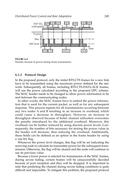
Distributed Power Control and Rate Adaptation 245NAV (G)(with pulses)EIFS EIFS EIFS EIFS EIFS EIFS EIFSTx powerMaxDPC levelRTSCTSDATAACKTimeFIGURE 6.4Periodic increase in power during frame transmission.6.5.2 Protocol DesignIn the proposed protocol, only the initial RTS-CTS frames for a new linkhave to be transmitted using the maximum power defined for the network.Subsequently, all frames, including RTS-CTS-DATA-ACK frames,will use the power calculated according to the proposed DPC scheme.The MAC header needs to be changed to allow power information to besent between the communicating nodes.In other words, the MAC frames have to embed the power informationthat is used for the current packet, as well as for any subsequentresponse. This process repeats for all transmissions occurring betweenany two nodes A and B resulting in an increase in overhead, whichcould cause a decrease in throughput. However, an increase inthroughput observed because of better channel utilization overcomesthe penalty introduced by the additional overhead. Moreover, thisoverhead can be further reduced by using discrete power levels. Consequently,the number of bits necessary for storing the power value inthe header will decrease, thus reducing the overhead. Additionally,these fields can be defined as an option in the frame header by usinga one-bit flag.Whenever the power level changes, this flag will be set indicating thereceiving node to calculate its transmitter power for the subsequent transmission.Otherwise, the flag will be cleared and the node will continue touse its previous value.Because a lower power is selected for transmission of the MAC frames,during severe fading, certain frames will be unsuccessfully decodedbecause of poor reception and they will be dropped. It is important tonote that predicting the channel during severe fading conditions is quitedifficult and impossible. To mitigate this problem, the proposed protocol
246 Wireless Ad Hoc and Sensor Networksincreases the power by a predefined safety factor before each retransmission,to reduce the packet drops.6.5.3 Channel UtilizationThough hidden-terminal problem occurrence increases with lower transmitterpowers, an improvement in channel utilization and throughputcan be seen by using the proposed MAC protocol. In fact, Figure 6.2depicts the enhancement in utilization that will occur when a lower transmitterpower is used for subsequent RTS-CTS transmissions wheneverthe RTS-CTS handshake between any two given nodes A and B has failed.In this scenario, node B will not respond to request from node A. Thiswill occur, for example, if node F is transmitting at the same time as nodeA is trying to send the RTS frame. Therefore, node B is unable to receivethe RTS frames because of a collision. After the predefined number ofretransmissions, node A will cease to send the packet. In such a case, nodeC will be able to start transmission earlier than in the case of usingmaximum power for RTS-CTS. As a result, the contention time for framesfrom certain nodes, such as C, decreases.Consider the scenario when maximum power is utilized for all RTS-CTS frames. Node C will decode the RTS frame because it was sent withthe maximum transmitter power defined for the network. Consequently,node C will update its NAV vector using the RTS frame. No transmissionoccurs; hence, the channel is idle. On the other hand, if the RTS frame issent at a power level calculated by the DPC, the node C will only detectthe RTS frame and will set its NAV vector to the EIFS time. Hence, shortlyafter EIFS, node C is free to initiate communication. Because of the availabilityof a channel to C, the throughput increases.This improvement applies to all nodes within the improvement areadepicted in Figure 6.2. Given the high density of nodes in the case ofwireless ad hoc networks, the probability of a node accessing the channelis quite high. Therefore, an increase in aggregated throughput is observedwith the proposed protocol.Because of higher channel utilization, the spatial reuse factor, whichis defined as the number of successful transmissions within a giventime interval for a given area, will increase for the proposed DPCscheme. For 802.11, the NAV vector will be set for an entire expectedduration of flow transmission; hence, there will be time intervals whenno transmissions take place. As the result, there will be fewer transmissionsfor a given time interval in comparison with the theoreticalcapacity of the radio channel. In our scheme, these idle periods aredetected, nodes are allowed to transmit sooner and, thus, the totalnumber of successful transmissions within a given time intervalincreases. Consequently, the spatial reuse factor increases for the proposedDPC when compared to 802.11.
- Page 217 and 218: 194 Wireless Ad Hoc and Sensor Netw
- Page 219 and 220: 196 Wireless Ad Hoc and Sensor Netw
- Page 221 and 222: 198 Wireless Ad Hoc and Sensor Netw
- Page 223 and 224: 200 Wireless Ad Hoc and Sensor Netw
- Page 225 and 226: 202 Wireless Ad Hoc and Sensor Netw
- Page 227 and 228: 204 Wireless Ad Hoc and Sensor Netw
- Page 229 and 230: 206 Wireless Ad Hoc and Sensor Netw
- Page 231 and 232: 208 Wireless Ad Hoc and Sensor Netw
- Page 233 and 234: 210 Wireless Ad Hoc and Sensor Netw
- Page 235 and 236: 212 Wireless Ad Hoc and Sensor Netw
- Page 237 and 238: 214 Wireless Ad Hoc and Sensor Netw
- Page 239 and 240: 216 Wireless Ad Hoc and Sensor Netw
- Page 241 and 242: 218 Wireless Ad Hoc and Sensor Netw
- Page 243 and 244: 220 Wireless Ad Hoc and Sensor Netw
- Page 245 and 246: 222 Wireless Ad Hoc and Sensor Netw
- Page 247 and 248: 224 Wireless Ad Hoc and Sensor Netw
- Page 249 and 250: 226 Wireless Ad Hoc and Sensor Netw
- Page 251 and 252: 228 Wireless Ad Hoc and Sensor Netw
- Page 253 and 254: 230 Wireless Ad Hoc and Sensor Netw
- Page 255 and 256: 232 Wireless Ad Hoc and Sensor Netw
- Page 257 and 258: 234 Wireless Ad Hoc and Sensor Netw
- Page 259 and 260: 236 Wireless Ad Hoc and Sensor Netw
- Page 261 and 262: 238 Wireless Ad Hoc and Sensor Netw
- Page 263 and 264: 240 Wireless Ad Hoc and Sensor Netw
- Page 265 and 266: 242 Wireless Ad Hoc and Sensor Netw
- Page 267: 244 Wireless Ad Hoc and Sensor Netw
- Page 271 and 272: 248 Wireless Ad Hoc and Sensor Netw
- Page 273 and 274: 250 Wireless Ad Hoc and Sensor Netw
- Page 275 and 276: 252 Wireless Ad Hoc and Sensor Netw
- Page 277 and 278: 254 Wireless Ad Hoc and Sensor Netw
- Page 279 and 280: 256 Wireless Ad Hoc and Sensor Netw
- Page 281 and 282: 258 Wireless Ad Hoc and Sensor Netw
- Page 283 and 284: 260 Wireless Ad Hoc and Sensor Netw
- Page 285 and 286: 262 Wireless Ad Hoc and Sensor Netw
- Page 287 and 288: 264 Wireless Ad Hoc and Sensor Netw
- Page 289 and 290: 266 Wireless Ad Hoc and Sensor Netw
- Page 291 and 292: 268 Wireless Ad Hoc and Sensor Netw
- Page 293 and 294: 270 Wireless Ad Hoc and Sensor Netw
- Page 295 and 296: 272 Wireless Ad Hoc and Sensor Netw
- Page 297 and 298: 274 Wireless Ad Hoc and Sensor Netw
- Page 299 and 300: 276 Wireless Ad Hoc and Sensor Netw
- Page 301 and 302: 278 Wireless Ad Hoc and Sensor Netw
- Page 303 and 304: 280 Wireless Ad Hoc and Sensor Netw
- Page 305 and 306: 282 Wireless Ad Hoc and Sensor Netw
- Page 307 and 308: 284 Wireless Ad Hoc and Sensor Netw
- Page 309 and 310: 286 Wireless Ad Hoc and Sensor Netw
- Page 311 and 312: 288 Wireless Ad Hoc and Sensor Netw
- Page 313 and 314: 290 Wireless Ad Hoc and Sensor Netw
- Page 315 and 316: 292 Wireless Ad Hoc and Sensor Netw
- Page 317 and 318: 294 Wireless Ad Hoc and Sensor Netw
Distributed Power Control <strong>and</strong> Rate <strong>Ad</strong>aptation 245NAV (G)(with pulses)EIFS EIFS EIFS EIFS EIFS EIFS EIFSTx powerMaxDPC levelRTSCTSDATAACKTimeFIGURE 6.4Periodic increase in power during frame transmission.6.5.2 Protocol DesignIn the proposed protocol, only the initial RTS-CTS frames for a new linkhave to be transmitted using the maximum power defined for the network.Subsequently, all frames, including RTS-CTS-DATA-ACK frames,will use the power calculated according to the proposed DPC scheme.The MAC header needs to be changed to allow power information to besent between the communicating nodes.In other words, the MAC frames have to embed the power informationthat is used for the current packet, as well as for any subsequentresponse. This process repeats for all transmissions occurring betweenany two nodes A <strong>and</strong> B resulting in an increase in overhead, whichcould cause a decrease in throughput. However, an increase inthroughput observed because of better channel utilization overcomesthe penalty introduced by the additional overhead. Moreover, thisoverhead can be further reduced by using discrete power levels. Consequently,the number of bits necessary for storing the power value inthe header will decrease, thus reducing the overhead. <strong>Ad</strong>ditionally,these fields can be defined as an option in the frame header by usinga one-bit flag.Whenever the power level changes, this flag will be set indicating thereceiving node to calculate its transmitter power for the subsequent transmission.Otherwise, the flag will be cleared <strong>and</strong> the node will continue touse its previous value.Because a lower power is selected for transmission of the MAC frames,during severe fading, certain frames will be unsuccessfully decodedbecause of poor reception <strong>and</strong> they will be dropped. It is important tonote that predicting the channel during severe fading conditions is quitedifficult <strong>and</strong> impossible. To mitigate this problem, the proposed protocol


