Bluetooth Radio Adapter, QST August 2013 - KG4JJH
Bluetooth Radio Adapter, QST August 2013 - KG4JJH
Bluetooth Radio Adapter, QST August 2013 - KG4JJH
- No tags were found...

Create successful ePaper yourself
Turn your PDF publications into a flip-book with our unique Google optimized e-Paper software.
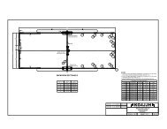
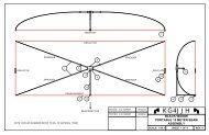
R6 = 7,500R5 = 2,200V D = 1 + 3.02 = 4.4dB = 20 * Log 10 (4.4) = 12.9M1 has a typical audio output level of 0.75 V rms. In a similar fashion, R1 and R6 form a ‐30 dBattenuator to convert the line output level from M1 to transceiver microphone level.R8 = 10KR2 = 300dB = 20 * Log 10 (33.3) = 30.46Two 3.5mm phone jacks supply the connections to the rig speaker/headphone output (J1), and the rigmicrophone (J2).Power SupplyThe voltage regulator accepts an input of 12 VDC and supplies the 3.3VDC required by the circuit. Theregulator features short‐circuit protection and supplies up to 500mA of current. Average current drawfor the circuit is 26mA.PC BoardPer the datasheet, the area around the M1 module should be free of any ground planes, power planes,trace routings, or metal. The recommended minimum clearance is 8mm, but additional clearance allowsimproved range and throughput. A PC board was designed and ordered from ExpressPCB 5 . I tookadvantage of their MiniBoard service which provides three 3.8 inch x 2.5 inch PCBs for $51. The<strong>Bluetooth</strong> <strong>Radio</strong> <strong>Adapter</strong> PCB is smaller than the standard MiniBoard size so it must be cut to fit theenclosure. Trim the PCB to size by removing the solid copper areas. Cut inside the copper areas (using aband saw or hack saw with a fine tooth blade) and finish removing the copper areas with a file.Construction and ToolsAll components are surface mount except J1‐J4, S1‐S3, D1‐D3, and FB1. Since this was my first project toimplement SMDs, I invested in a few tools and supplies: Magnifying lamp (3 diopter) Temperature controlled soldering station (Hakko FX‐888) Soldering tips (Hakko T18‐I, T18‐C05, T18‐B) Tweezers (DigiKey# EROP3CSA‐ND) 0.020" diameter solder (Mouser# 533‐24‐6337‐9702) De‐soldering braid (Mouser# 5878‐60‐1‐5)Another option for SMD soldering is a hot air rework station 6 . It uses hot air to solder the componentsusing solder paste. All components mount on the component side. Install all surface mount componentsfirst to allow room for the soldering iron. Inspect the PCB for correct components, componentorientation, good solder joints, and remove any solder bridges using the de‐soldering braid. Mount thetwo LEDs by bending the leads per the detail on drawing page 2 of 3. Also, remove the plastic tabs onthe bottom of J1 and J2.<strong>Bluetooth</strong> <strong>Radio</strong> <strong>Adapter</strong>, <strong>KG4JJH</strong> Page 2 of 5