

Table of Contents - TG Drives
Table of Contents - TG Drives
Table of Contents - TG Drives

You also want an ePaper? Increase the reach of your titles
YUMPU automatically turns print PDFs into web optimized ePapers that Google loves.
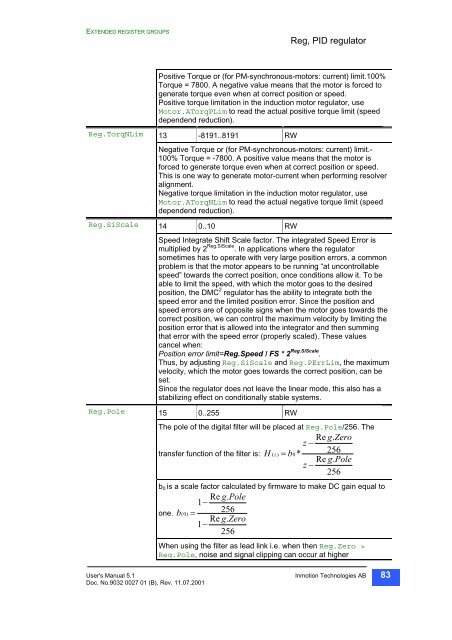
EXTENDED REGISTER GROUPS<br />
Positive Torque or (for PM-synchronous-motors: current) limit.100%<br />
Torque = 7800. A negative value means that the motor is forced to<br />
generate torque even when at correct position or speed.<br />
Positive torque limitation in the induction motor regulator, use<br />
Motor.ATorqPLim to read the actual<br />
positive torque limit (speed<br />
dependend reduction).<br />
Reg.TorqNLim 13 -8191..8191 RW<br />
Negative Torque or (for PM-synchronous-motors: current) limit.-<br />
100% Torque = -7800. A positive value means that the motor is<br />
forced to generate torque even when at correct position or speed.<br />
This is one way to generate motor-current when performing resolver<br />
alignment.<br />
Negative torque limitation in the induction motor regulator, use<br />
Motor.ATorqNLim to read<br />
the actual negative torque limit (speed<br />
dependend reduction).<br />
Reg.SiScale 14 0..10 RW<br />
Speed Integrate Shift Scale factor. The integrated Speed Error is<br />
multiplied by 2<br />
Reg.SiScale and Reg.PErrLim, the maximum<br />
Reg.SiScale . In applications where the regulator<br />
sometimes has to operate with very large position errors, a common<br />
problem is that the motor appears to be running “at uncontrollable<br />
speed” towards the correct position, once conditions allow it. To be<br />
able to limit the speed, with which the motor goes to the desired<br />
position, the DMC 2 regulator has the ability to integrate both the<br />
speed error and the limited position error. Since the position and<br />
speed errors are <strong>of</strong> opposite signs when the motor goes towards the<br />
correct position, we can control the maximum velocity by limiting the<br />
position error that is allowed into the integrator and then summing<br />
that error with the speed error (properly scaled). These values<br />
cancel when:<br />
Position error limit=Reg.Speed / FS * 2 Reg.SiScale .<br />
Thus, by adjusting<br />
velocity, which the motor goes towards the correct position, can be<br />
set.<br />
Since the regulator does not leave the linear mode, this also has a<br />
stabilizing effect on conditionally stable systems.<br />
Reg.Pole 15 0..255 RW<br />
Reg, PID regulator<br />
The pole <strong>of</strong> the digital filter will be placed at Reg.Pole/256. The<br />
Re g.<br />
Zero<br />
z −<br />
transfer function <strong>of</strong> the filter is: H * 256<br />
( z)<br />
= b0<br />
Re g.<br />
Pole<br />
z −<br />
256<br />
b0 is a scale factor calculated by firmware to make DC gain equal to<br />
Re g.<br />
Pole<br />
1−<br />
one. b 256<br />
( 0)<br />
=<br />
Re g.<br />
Zero<br />
1−<br />
256<br />
When using the filter as lead link i.e. when then Reg.Zero ><br />
Reg.Pole,<br />
noise and<br />
signal clipping can occur at higher<br />
User's Manual 5.1 Inmotion Technologies AB<br />
Doc. No.9032 0027 01 (B), Rev. 11.07.2001<br />
83


