Table of Contents - TG Drives
Table of Contents - TG Drives
Table of Contents - TG Drives
You also want an ePaper? Increase the reach of your titles
YUMPU automatically turns print PDFs into web optimized ePapers that Google loves.
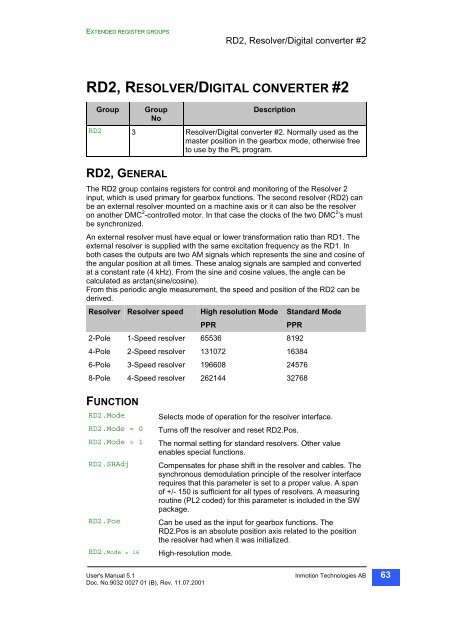
EXTENDED REGISTER GROUPS<br />
RD2, Resolver/Digital converter #2<br />
RD2, RESOLVER/DIGITAL CONVERTER #2<br />
Group Group<br />
No<br />
Description<br />
RD2 3 Resolver/Digital converter #2. Normally used as the<br />
master position in the gearbox mode, otherwise free<br />
to use by the PL program.<br />
RD2, GENERAL<br />
The RD2 group contains registers for control and monitoring <strong>of</strong> the Resolver 2<br />
input, which is used primary for gearbox functions. The second resolver (RD2) can<br />
be an external resolver mounted on a machine axis or it can also be the resolver<br />
on another DMC 2 -controlled motor. In that case the clocks <strong>of</strong> the two DMC 2 ’s must<br />
be synchronized.<br />
An external resolver must have equal or lower transformation ratio than RD1. The<br />
external resolver is supplied with the same excitation frequency as the RD1. In<br />
both cases the outputs are two AM signals which represents the sine and cosine <strong>of</strong><br />
the angular position at all times. These analog signals are sampled and converted<br />
at a constant rate (4 kHz). From the sine and cosine values, the angle can be<br />
calculated as arctan(sine/cosine).<br />
From this periodic angle measurement, the speed and position <strong>of</strong> the RD2 can be<br />
derived.<br />
Resolver Resolver speed High resolution Mode Standard Mode<br />
PPR PPR<br />
2-Pole 1-Speed resolver 65536 8192<br />
4-Pole 2-Speed resolver 131072 16384<br />
6-Pole 3-Speed resolver 196608 24576<br />
8-Pole 4-Speed resolver 262144 32768<br />
FUNCTION<br />
RD2.Mode Selects mode <strong>of</strong> operation for the resolver interface.<br />
RD2.Mode = 0 Turns <strong>of</strong>f the resolver and reset RD2.Pos.<br />
RD2.Mode = 1 The normal setting for standard resolvers. Other value<br />
enables special functions.<br />
RD2.SHAdj Compensates for phase shift in the resolver and cables. The<br />
synchronous demodulation principle <strong>of</strong> the resolver interface<br />
requires that this parameter is set to a proper value. A span<br />
<strong>of</strong> +/- 150 is sufficient for all types <strong>of</strong> resolvers. A measuring<br />
routine (PL2 coded) for this parameter is included in the SW<br />
package.<br />
RD2.Pos Can be used as the input for gearbox functions. The<br />
RD2.Pos is an absolute position axis related to the position<br />
the resolver had when it was initialized.<br />
RD2.Mode = 16 High-resolution mode.<br />
User's Manual 5.1 Inmotion Technologies AB<br />
Doc. No.9032 0027 01 (B), Rev. 11.07.2001<br />
63


