Table of Contents - TG Drives
Table of Contents - TG Drives Table of Contents - TG Drives
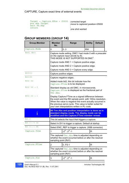
120 EXTENDED REGISTER GROUPS CAPTURE, Capture exact time of external events Target = Capture.RPos + 25000 pos abs Target wait PG.Rdy return GROUP MEMBERS (GROUP 14) Group.Member Member No. ;corrected target ;move to captured position+25000 ; ;one shot wanted Range Ability Default Capture.Mode 0 0..3 RW Bit0, Bit1 Capture mode setting. DMC1 had mode 0 with a prescaler on the capture input (divide by 8). THIS MODE IS NOT SUPPORTED IN DMC 2 . Capture mode AND 1 = Capture positive edge. Capture mode AND 2 = Capture positive edge. Capture mode AND 3 = Capture every edge. Bit0(1) Capture positive edges. Bit1(2) Capture negative edges. Bit2 (4) Added mode bit2, this bit indicate how the Capture.FTime is to be displayed. Bit2 (4) = 0 Standard display as old DMC, in microseconds. Capture.FTime is displayed as the fractional part of Tmr.Abs. Bit2 (4) = 1 Display Capture.FTime as a signed difference between the event and the RD sample point, with 100ns resolution. When the value is negative the event actually occurred in the previous servo cycle. This value is better suited for your own interpolations written in PL-code. i All Tmr.Abs and position interpolation is done as in standard display mode. The display mode can be modified and the Capture.FTime member reread. Bit 3 This bit selects the input that triggers a capture. Bit 3 = 0 (0) Select In.DI1 to trigger a capture. Default at startup. Bit 3 = 1 (8) Select ENC_REF to trigger a capture. (X6B connector) Capture.Time 1 -2 31 ..2 31 -1 R The captured Tmr.Abs time is adjusted depending on whether the event occurred before or after the resolver sampling point (Rd1). Capture.FTime 2 0..FS-1 R The captured Tmr.Abs time is adjusted depending on whether the event occurred before or after the resolver sampling point (Rd1). Capture.Pos 3 -2 31 ..2 31 -1 R User's Manual 5.1 Inmotion Technologies AB Doc. No.9032 0027 01 (B), Rev. 11.07.2001
EXTENDED REGISTER GROUPS CAPTURE, Capture exact time of external events The RD1.Pos at the time of the event. The RD1.Pos is sampled with the FS (currently 1000 Hz) frequency, and the resulting position is then interpolated from that position and speed. Captured and interpolated RD1.Pos. Capture.RPos 4 -2 31 ..2 31 -1 R Same as Capture.Pos, but affected by PG.PosOffs Capture.Enable 5 0..3 RW Control and indicate operation of the CAPTURE mechanism. Capture.Enable is cleared when the event occurs and therefore, must be re-enabled every time a new capture is desired. Bit0 (1) = 1 Enable this function and PL-code captures interrupt. Bit0 (1) = 1 Bit1 (2) = 1 The mode for rapidly stopping the motor. Capture.Speed 6 -32767000 .. 32767000 R The current value of RD1.Speed when the event occurred. Captured RD1.Speed. Capture.SetTorque 7 -32767 .. 32767 RW Capture.SetTorque and Capture.SetPHDelay values are used during/after the HSI capture interrupt is executed. The HSI capture interrupt can be used if a minimum delay start or stop of the motor is desired. The interrupt does the following: OR Reg.Mode, 128 ; Turn off regulator output. LET Reg.Torque = Capture.SetTorque ; Set user specified torque LET Motor.PhDelay = Capture.SetPhDelay ; Set optimum commutation for fast ACC/DECEL. ; The user Capture interrupt routine is then called to do the remaining control. Capture.SetPHDelay 8 -32767 * FS .. 32767 * FS R See Capture.SetTorque for description. Capture.GPos 9 -2 31 ..2 31 -1 R Captured the Gear.Pos interpolated to the time of the event. The Gear.Pos is sampled with the FS (currently 1000 Hz) frequency, and the resulting position is then interpolated from that position and speed. Capture.GSpeed 10 -32767 * FS .. 32767 * FS R Captured the Gear.Speed to the time of the event. Capture.APos 11 -2 31 ..2 31 -1 R Captured the Pg.APos at the time of the event. See “Compatibility issue”. Capture.ASpeed 12 -32767 * FS .. 32767 * FS R User's Manual 5.1 Inmotion Technologies AB Doc. No.9032 0027 01 (B), Rev. 11.07.2001 121
- Page 69 and 70: EXTENDED REGISTER GROUPS Pos Inc Pr
- Page 71 and 72: EXTENDED REGISTER GROUPS Pg.ASpeed
- Page 73 and 74: EXTENDED REGISTER GROUPS MOTOR, MOT
- Page 75 and 76: EXTENDED REGISTER GROUPS 2-Pole: 81
- Page 77 and 78: EXTENDED REGISTER GROUPS Motor.Base
- Page 79 and 80: EXTENDED REGISTER GROUPS REG, PID R
- Page 81 and 82: EXTENDED REGISTER GROUPS GROUP MEMB
- Page 83 and 84: EXTENDED REGISTER GROUPS Positive T
- Page 85 and 86: EXTENDED REGISTER GROUPS Reg, PID r
- Page 87 and 88: EXTENDED REGISTER GROUPS Gear.Incr
- Page 89 and 90: EXTENDED REGISTER GROUPS GROUP MEMB
- Page 91 and 92: EXTENDED REGISTER GROUPS Gear, Elec
- Page 93 and 94: EXTENDED REGISTER GROUPS TMR, SYSTE
- Page 95 and 96: EXTENDED REGISTER GROUPS Tmr, Syste
- Page 97 and 98: EXTENDED REGISTER GROUPS RELATED IT
- Page 99 and 100: EXTENDED REGISTER GROUPS SysIo.ADC1
- Page 101 and 102: EXTENDED REGISTER GROUPS Bit10 (102
- Page 103 and 104: EXTENDED REGISTER GROUPS INT, INTER
- Page 105 and 106: EXTENDED REGISTER GROUPS Bit2 (4) =
- Page 107 and 108: EXTENDED REGISTER GROUPS Int, Inter
- Page 109 and 110: EXTENDED REGISTER GROUPS IN, DIGITA
- Page 111 and 112: EXTENDED REGISTER GROUPS X7A:6. In.
- Page 113 and 114: EXTENDED REGISTER GROUPS X7B:33. Ou
- Page 115 and 116: EXTENDED REGISTER GROUPS GROUP MEMB
- Page 117 and 118: EXTENDED REGISTER GROUPS Vector, In
- Page 119: EXTENDED REGISTER GROUPS CAPTURE, C
- Page 123 and 124: EXTENDED REGISTER GROUPS CAPTURE, C
- Page 125 and 126: EXTENDED REGISTER GROUPS Ana.ConnTM
- Page 127 and 128: EXTENDED REGISTER GROUPS EEPROM Gro
- Page 129 and 130: EXTENDED REGISTER GROUPS Bit(0..3)
- Page 131 and 132: EXTENDED REGISTER GROUPS GROUP MEMB
- Page 133 and 134: EXTENDED REGISTER GROUPS RD1CORR, P
- Page 135 and 136: EXTENDED REGISTER GROUPS OptAD, ana
- Page 137 and 138: EXTENDED REGISTER GROUPS OptAD.7 7
- Page 139 and 140: EXTENDED REGISTER GROUPS LAN1, LOCA
- Page 141 and 142: EXTENDED REGISTER GROUPS WriteLAN1
- Page 143 and 144: EXTENDED REGISTER GROUPS LAN1, Loca
- Page 145 and 146: EXTENDED REGISTER GROUPS LAN1, Loca
- Page 147 and 148: EXTENDED REGISTER GROUPS LAN1.ErrVe
- Page 149 and 150: EXTENDED REGISTER GROUPS MsgObjLAN1
- Page 151 and 152: EXTENDED REGISTER GROUPS isrDone: M
- Page 153 and 154: EXTENDED REGISTER GROUPS MsgObjLAN2
- Page 155 and 156: EXTENDED REGISTER GROUPS Denominato
- Page 157 and 158: EXTENDED REGISTER GROUPS ABIN Group
- Page 159 and 160: EXTENDED REGISTER GROUPS DSTORE, Gr
- Page 161 and 162: EXTENDED REGISTER GROUPS PARAREA, G
- Page 163 and 164: EXTENDED REGISTER GROUPS XENDAT, Gr
- Page 165 and 166: EXTENDED REGISTER GROUPS wait tmr.t
- Page 167 and 168: EXTENDED REGISTER GROUPS XENDAT.Tra
- Page 169 and 170: EXTENDED REGISTER GROUPS XENDAT, Af
120<br />
EXTENDED REGISTER GROUPS<br />
CAPTURE, Capture exact time <strong>of</strong> external events<br />
Target = Capture.RPos + 25000<br />
pos abs Target<br />
wait PG.Rdy<br />
return<br />
GROUP MEMBERS (GROUP 14)<br />
Group.Member Member<br />
No.<br />
;corrected target<br />
;move to captured position+25000<br />
;<br />
;one shot wanted<br />
Range Ability Default<br />
Capture.Mode 0 0..3 RW<br />
Bit0, Bit1 Capture mode setting. DMC1 had mode 0 with a prescaler<br />
on the capture input (divide by 8).<br />
THIS MODE IS NOT SUPPORTED IN DMC 2 .<br />
Capture mode AND 1 = Capture positive edge.<br />
Capture mode AND 2 = Capture positive edge.<br />
Capture mode AND 3 = Capture every edge.<br />
Bit0(1) Capture positive edges.<br />
Bit1(2) Capture negative edges.<br />
Bit2 (4)<br />
Added mode bit2, this bit indicate how the<br />
Capture.FTime is to be displayed.<br />
Bit2 (4) = 0<br />
Standard display as old DMC, in microseconds.<br />
Capture.FTime is displayed<br />
as the fractional part <strong>of</strong><br />
Tmr.Abs.<br />
Bit2 (4) = 1 Display Capture.FTime as a signed difference between<br />
the event and the RD sample point, with 100ns resolution.<br />
When the value is negative the event actually occurred in<br />
the previous servo cycle. This value is better suited for<br />
your own interpolations written in PL-code.<br />
i<br />
All Tmr.Abs and position interpolation is done as in<br />
standard display mode. The display mode can be<br />
modified and the Capture.FTime member reread.<br />
Bit 3 This bit selects the input that triggers a capture.<br />
Bit 3 = 0 (0) Select In.DI1 to trigger a capture. Default at startup.<br />
Bit 3 = 1 (8) Select ENC_REF to trigger a capture. (X6B connector)<br />
Capture.Time 1 -2 31 ..2 31 -1 R<br />
The captured Tmr.Abs time is adjusted<br />
depending on<br />
whether the event occurred before or after the resolver<br />
sampling point (Rd1).<br />
Capture.FTime 2 0..FS-1 R<br />
The captured Tmr.Abs time is adjusted<br />
depending on<br />
whether the event occurred before or after the resolver<br />
sampling point (Rd1).<br />
Capture.Pos 3 -2 31 ..2 31 -1 R<br />
User's Manual 5.1 Inmotion Technologies AB<br />
Doc. No.9032 0027 01 (B), Rev. 11.07.2001


