advanced time interval counter & analyzer based on eet-method ...
advanced time interval counter & analyzer based on eet-method ... advanced time interval counter & analyzer based on eet-method ...
ADVANCED TIME INTERVAL COUNTER &ANALYZER BASED ON EET-METHODAPPLICATIONYu. Artyukh, V. Bespal’ko, A. Rybakov, V. VedinInstitute of Electronics and Computer Science, LatviaDzerbenes 14, Riga, LV1006, LatviaE-mail: artyukh@edi.lvABSTRACTA system for signal analysis in the Modulation Domain, calledTime Interval Counter & Analyzer, is discussed. The Counterallows to measure
- Page 3 and 4: events. Therefore a very careful co
ADVANCED TIME INTERVAL COUNTER &ANALYZER BASED ON EET-METHODAPPLICATIONYu. Artyukh, V. Bespal’ko, A. Rybakov, V. VedinInstitute of Electr<strong>on</strong>ics and Computer Science, LatviaDzerbenes 14, Riga, LV1006, LatviaE-mail: artyukh@edi.lvABSTRACTA system for signal analysis in the Modulati<strong>on</strong> Domain, calledTime Interval Counter & Analyzer, is discussed. The Counterallows to measure <str<strong>on</strong>g>time</str<strong>on</strong>g> <str<strong>on</strong>g>interval</str<strong>on</strong>g>s versus <str<strong>on</strong>g>time</str<strong>on</strong>g> in the rangeextended up to hundreds of millisec<strong>on</strong>ds. Due to applicati<strong>on</strong> ofan original EET-<strong>method</strong>, it was possible to reach excepti<strong>on</strong>allyhigh resoluti<strong>on</strong> (
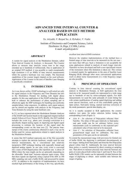
events. Therefore a very careful c<strong>on</strong>structi<strong>on</strong> of the corresp<strong>on</strong>dingunit is required. Principally the best resoluti<strong>on</strong>, which has beenobtained in our experiments, is about 5 ps.The temporal instability of the measurement results, includingcertain instability of the test signal, in our experiments did notexceed 5-7 ps per hour (peak-to-peak) in typical operati<strong>on</strong>alc<strong>on</strong>diti<strong>on</strong>s (Figure 3).fully exclude a temporal instability of the external circuits relatedwith test signal forming.5. CONCLUSIONSObtained results showed that EET-<strong>method</strong> also well suited forcertain specific applicati<strong>on</strong>s related with wide-range <str<strong>on</strong>g>time</str<strong>on</strong>g> <str<strong>on</strong>g>interval</str<strong>on</strong>g>measurement. Even in this case it offers high performance incombinati<strong>on</strong> with simplicity of design. We plan further to developa next opti<strong>on</strong> of the <str<strong>on</strong>g>counter</str<strong>on</strong>g> allowing fully c<strong>on</strong>tinuous <str<strong>on</strong>g>time</str<strong>on</strong>g><str<strong>on</strong>g>interval</str<strong>on</strong>g> measurement in an extra-wide range.6. REFERENCES[1] Yu. Artyukh, A. Rybakov, V. Vedin. “Modulati<strong>on</strong> DomainAnalyzer of the DASP-Lab System”. Proceeding of the 1997Internati<strong>on</strong>al Workshop <strong>on</strong> Sampling Theory andApplicati<strong>on</strong>, June,19997, Aveiro, Portugal, p.371-383.[2] Yu. Artyukh, A. Rybakov, V. Vedin. “A new Approach toHigh Performance C<strong>on</strong>tinuous Time Interval Counting”.Proceeding of the XI Polish Nati<strong>on</strong>al C<strong>on</strong>ference Applicati<strong>on</strong>of Microprocessors in Automatic C<strong>on</strong>trol and Measurements,October, 1998, Warsaw, Poland, p. 139-143.Figure 3. Typical l<strong>on</strong>g-term deviati<strong>on</strong> of c<strong>on</strong>tinuouslymeasured <str<strong>on</strong>g>time</str<strong>on</strong>g> <str<strong>on</strong>g>interval</str<strong>on</strong>g>However, to evaluate this parameter more correctly, we could notANNEXMain Characteristics of the Counter• Inputs Pulse levels - NIM
Pulse width - >2 nsSlope - rising or falling edgeImpedance - 50 Ω• Time Interval MeasurementMeasurement range - 50 ns to 320 msMinimum “dead <str<strong>on</strong>g>time</str<strong>on</strong>g>” - 50 nsSingle shot RMS resoluti<strong>on</strong> (depending <strong>on</strong>allowable “dead <str<strong>on</strong>g>time</str<strong>on</strong>g>”):best < 15 psworst < 40 psTemporal instability - < + 3 ps/h• GatingGate R (<strong>on</strong> line computed)Range - 50 ns to 165 msDelay - 15 µsec to 335 msVariati<strong>on</strong> step - 20 ns min.Gate C (opti<strong>on</strong>al setting)Range - 50 ns to 1 µsDelay - 50 ns to 3 µsVariati<strong>on</strong> step - 50 ns min.• Start-pulse TimingMeasurement range - 24 hoursLSB resoluti<strong>on</strong> - 10 ns• Synchr<strong>on</strong>izing of the MeasurementStart of measurement - at beforehandprogrammable <str<strong>on</strong>g>time</str<strong>on</strong>g> or manuallyCycle start-up - by external signalor after finishing the every current cycleMaximum measurement rate -up to 20 cycles/s• PC requirementsIBM compatible 486 or higher PCRunning Widows 3.1 or higher>8 MB RAM; >20 MB Hard Disk SpaceEPP Parallel Port• External <str<strong>on</strong>g>time</str<strong>on</strong>g>base5 or 10 MHz reference1 Hz synchr<strong>on</strong>izing marks• GeneralPower - 220 VAC + 10%Dimensi<strong>on</strong>s - 405x50x320 mmWeight - 3.6 kg


