GAS-FIRED AIR MAKE-UP UNITS - Aerovent
GAS-FIRED AIR MAKE-UP UNITS - Aerovent
GAS-FIRED AIR MAKE-UP UNITS - Aerovent
- No tags were found...

Create successful ePaper yourself
Turn your PDF publications into a flip-book with our unique Google optimized e-Paper software.
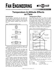
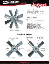
Construction FeaturesPipetrainLiquid-tight conduit is used for all interconnecting wiring.Approved safety shutoff valves are standard.ControlsMounted in a NEMA 12 enclosure. See page 10.Velocity MonitorSenses only velocity pressure(pressure due to airflow) andis not affected by the systemstatic pressure. If the inletor discharge is accidentallyrestricted or filters be-comeclogged, this control willcause unit shutdown.Weather Cover DoorRaintight channeled edgeswith rustproof, quick clamplever type latches.Heavy-duty DamperTwelve-gauge frame and linkage with 16-gauge blades. Pivotsare mounted in 1 ∕2" oil bronze bushings. Blades do not extendbeyond the frame.BurnerNew NP (Natural/Propane)airflow burner has stainlesssteel mixing plates and castiron manifold assembly.BurnersectionBearingsCast iron housing pillow block ball bearings or spherical rollerbearings.Safety GuardRugged safety guard designed for easy removal for access tofan drive components.Unit inletshowingburnerHousingHeavy-gauge corner-to-corner welded steel housing sectionsare flanged or angle construction and are bolted together.SheavesClose grain machined cast iron with split taper bushing.BeltsA, B, or C section belts selected for 150% of horsepowerrequirement.ShaftMachined carbon steel.7 <strong>Aerovent</strong> Bulletin 864
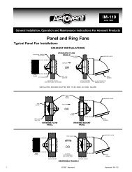
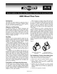
Control PanelThe main control panel is designed with the service technicianin mind. The panel is housed in a NEMA 12 enclosure and islicensed to carry the UL and CSA label under the 508 listing.The panel meets all standards of the National Electric Codeand includes as standard:• Industrial duty circuit breaker with flange mount handle• Stepdown control transformer• Motor starter with overloads• Ignition transformer• Honeywell 7800 series primary flame safeguard system• Maxitrol temperature controller• Purge and reset timersThe incorporation of the Honeywell 7800 flame relayoffers the customer the following options:• Remote relay reset (reset lockout from remote panel)• Communications capability (provides local and remotetroubleshooting with 386 CPU)• Fault history (readout of six most recent faults from LEDreadout for troubleshooting flame failures)A unique feature that is standard in all control panels is the<strong>Aerovent</strong> Circuit Analyzer. The analyzer gives indication ofcircuit continuity on unit start-up, thus allowing maintenancepersonnel quick determination of a faulty component whichsimplifies troubleshooting.Customized systems are available, including but not limitedto remote digital temperature readout and 4-20mA or 0-10Vinput to our controller.Control transformerMotor starterCircuit breaker orfused disconnect switch(shown)Ignition transformerMaxitrol temperaturecontrollerCircuit analyzerNon-recycle relayFlame safety relayReset timer10 <strong>Aerovent</strong> Bulletin 864
Sequence of Operation – Gas BurnerSOFFWRemote Station Selector Switch starts and stops all unit functions. In “winter” position, operates fan and burnercontrol system in proper sequence. In “summer” position, operates fan only. Serves also as manual reset.Remote Station Indicator Lamp shows when selector is in either operating position.Mild Weather Thermostat causes unit to automatically shift from winter to summer, whichever is required,according to outside temperature (adjustable).Reset Timer allows timed bypass of the low temperature thermostat, permitting unit to start when the temperatureis below the set point of the low limit thermostat.Low Limit Thermostat causes complete unit shutdown if discharge air temperature falls dangerously low.Stop Relay causes complete unit shutdown in the event of any malfunction in the flame safety or fan starter circuit.Damper Motor opens damper when selector switch is turned on.Damper End Switch starts the fan when damper reaches open position.Fan Starter provides fan motor protection station, shows damper open and fan on.Fan On Indicator at remote operating station, shows damper open and fan on.Purge Timer provides 5-second prepurge time.Low Gas Pressure Switch causes shutdown in event of insufficient gas pressure. (Manual reset on the switch.)High Gas Pressure Switch causes shutdown in event of excessive gas pressure. (Manual reset on the switch.)Airflow Switch senses air velocity pressure and will cause complete unit shutdown if airflow drops below requirementfor satisfactory combustion. (Manual reset by the selector switch.)High Limit Thermostat causes complete shutdown if discharge air temperature exceeds set point. Adjustablemanual reset.Combustion Safeguard Relay controls ignition, pilot and safety shut-off valve. Supervises main flame, closesSSOV instantly upon power or flame failure, causes complete shutdown in case of unproven pilot or flame failure afterignition of the main flame. (Remote manual reset from operating station.)Indicator Lamp at remote station, shows burner on.Non-recycle Timer provides 10-second limit for ignition of pilot and subsequent establishment of main flame.Interrupts pilot for main flame supervision, prevents recycling in the event of flame failure.Low Fire Start integral with modulating valve.Modulator/Regulator ValveC B AFULLY MODULATING TEMPERATURE CONTROL SYSTEMSA Outlet Temperature Control System (OTC) holds constant outlet temperature adjustable at the remoteoperating station and has outdoor temperature compensation.Discharge Air Temperature Thermostat actuates the modulating regulator to hold average outlet temperatureto control point. Remotely adjustable.B Outlet Control System with room override (OTC-RO) (optional) maintains room temperature to remotethermostat setting and is discharge temperature compensated. Primarily used for morning warmup or when overheaddoors open.Room Thermostat resets the discharge air thermostat according to room requirements holding the room temperatureto the control point. (Adjustable)Discharge Air Temperature Thermostat automatically limits extreme changes in discharge temperature.(Adjustable)C Modulated Room Temperature Control (MRTC) (optional) maintains room temperature within very narrowlimits, provides extreme accuracy and rapid response to small temperature changes.11 <strong>Aerovent</strong> Bulletin 864
Digital Temperature Control<strong>Aerovent</strong>’s Direct Digital Control System ® is a PC-based controlsystem that can remotely monitor and control all aspectsof your HVAC system from your PC. Each Air Make-up unithas a stand-alone controller which can be connected to anIBM-compatible PC. The Windows ® -based* software canbe easily customized to include and display the informationnecessary for smooth operation of your system. The completesystem, including PC, is available from <strong>Aerovent</strong>. <strong>Aerovent</strong>can supply Air Make-up units compatible for use with an existingDDC system or for future installation of a DDC system.CapabilitiesA typical DDC System would monitor system status, outsideair temperature, room air temperature and discharge air temperature.It can control turning units on and off, room pressure(via VFD or recirculation), discharge temperature andsummer/winter changeover. It can also control exhaust fans,night temperature setback, and alarm faults.Unit 1 Unit 2 Unit 3 Unit 4OfficeFactory FloorUnit 5Direct DigitalControl SoftwareUnit x*Windows ® is a registered trademark of Microsoft Corporation.12 <strong>Aerovent</strong> Bulletin 864
Digital Temperature ControlTypical Direct Digital ControlPackage For Gas-Fired AirMake-Up• Maxitrol A200 Signal Conditioner• Setpoints and sequence, programmed and tested at<strong>Aerovent</strong> factory• Stand-alone controller for each unit which can be connectedto an IBM-compatible PC• On-site start-up support and trainingDDC System Will Monitor:• Outside air temperature• Discharge air temperature• Room air temperature (optional)• Motor amperage (optional)• Gas valve position• High/low gas pressure status• Airflow status• Fan status• Flame status• Room pressure (optional for 80/20 recirculation or VFDapplications)• Summer/winter status• Damper status• High temp status• Burner statusSequence of Operation:• Turn unit on• Select summer/winter operation according to outside airtemperature• If discharge air temperature is below low limit setpoint formore than 3 minutes, turn unit off and send fault signal• If discharge air temperature is above high limit setpoint,turn unit off and send fault signal• Turn unit off upon detection of status changeSummer:• Automatically select summer mode if outside air temperatureis above the setpoint• Monitor all inputs• Disable burner• Send output to recirculation dampers or VFD accordingto room pressure (optional)Winter:• Automatically select winter mode if outside air temperatureis below setpoint• When fan, burner, and airflow are on, Maxitrol A200modulates the gas valve according to the discharge orroom temperature setpoint• Send output to recirculation dampers or VFD accordingto room pressure (optional)13 <strong>Aerovent</strong> Bulletin 864
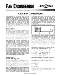
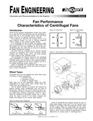
Digital Temperature ControlThis is the main screen of the Direct Digital Temperature Control System. It displays the basic status of the unit(s) and the system.From here you can jump to screens (shown next page) which show the status of individual units.Clicking here willshow a summary ofthe system status. Thisis customizable toinclude any or all datapoints, for example:• List all units• On/Off• Discharge set-• point• Temperature at• discharge• Outside air• temperatureSummary#.##"W.C.Unit 5Unit 6#.##"W.C.Unit 7Main Menu for Air-Make Up UnitsClick on button for detailed Unit Status#.##"W.C.#.##"W.C. #.##"W.C.Unit 4 Unit 3Your BuildingUnit 2#.##"W.C.Unit 1#.##"W.C.Unit 11#.##"W.C.Unit 8#.##"W.C.Unit 9#.##"W.C.Unit 10#.##"W.C.Red = OffGreen = OnClicking an individual unit will displaythe control screen for that unit, shownon the next page.Background color indicates unitstatus – green for “On,” red for“Off.”• Can add an “Alarm” state• Can customize name,e.g. “Baghouse”14 <strong>Aerovent</strong> Bulletin 864
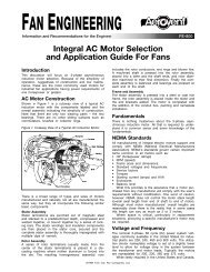
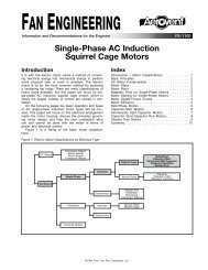
Digital Temperature ControlThis screen displays data for individual units. Most functions of the unit can be included or excluded and can be controlledfrom here.Indicators for status ofindividual systems. Greenfor “On,” Red for “Off.”Displays unit’scurrent readings.Green = Limit OKRed = Limit Not OKE-StopUnit OnDamper OpenFan OnAir FlowHigh Gas PressureLow Gas PressureHigh TemperatureFlame FailureSummerWinterBurner OnStart Unit Stop UnitAEROVENT <strong>AIR</strong> <strong>MAKE</strong>-<strong>UP</strong>### FFiltered AirTemp Discharge##Deg. FDischargeAir TempSet Point### %Fan Speed#.##"W.C.BuildingPressureBuilding PressureSet Point #.##Total FilterDrop#.##### FAir TempInlet### FAir TempDischargeANALOG SENSORREADINGS### FFiltered InletAir TempClose## Summer Change Over Temp## Winter Change Over TempDisplayspressuredropacrossfiltersCan start or stop theunit from this windowDisplays buildingpressure. This isadjustable fromthis window.Displays summer andwinter changeovertemperatures. Theseare adjustable fromthis window.15 <strong>Aerovent</strong> Bulletin 864
Performance DataModel GA Propeller Gas-fired Air Make-up UnitsStandard ConstructionCatalog Numbering SystemAssign catalog number by using the numbering system outlinedin the example at right and indicate discharge position.DefinitionsBTU/HR. is sensible heat release. To determine cfh gas input,divide Btu by the net heat value of the fuel.CFM is net volume at discharge at 70°F.EXT. SP (external static pressure) is pressure available foraddition of ducts.All units are furnished with burners having 25 to 1 turndownratio.Gas Air Make-upPropellerFan SizeBlade DesignNo. of BladesAngle SettingFan RPMMotor HPGA 30 L 4 22 1081 - 1<strong>AIR</strong> <strong>MAKE</strong>-<strong>UP</strong> WITHOUT FILTER CABINETCATALOG NUMBERSTEMPERATURE RISE: 0° TO 92°CFM EXT. SP FAN SIZE FAN RPM MTR. HP BTU/HR.GA-30L422-1081-1 6,000 0 30" 1081 1 600,000GA-30L422-1290-1 1 ⁄2 6,000 1⁄4 30" 1290 1 1 ⁄2 600,000GA-30L422-1493-3 6,000 1⁄2 30" 1493 3 600,000GA-30L422-1333-2 10,000 0 30" 1333 2 1,000,000GA-30L422-1467-3 10,000 1⁄4 30" 1467 3 1,000,000GA-30L422-1599-5 10,000 1⁄2 30" 1599 5 1,000,000GA-30L422-1730-5 10,000 3⁄4 30" 1730 5 1,000,000GA-36L422-1154-3 15,000 0 36" 1154 3 1,500,000GA-36L422-1255-3 15,000 1⁄4 36" 1255 3 1,500,000GA-36L422-1351-5 15,000 1⁄2 36" 1351 5 1,500,000GA-36L422-1445-5 15,000 3⁄4 36" 1445 5 1,500,000GA-42L422-976-3 20,000 0 42" 976 3 2,000,000GA-42L422-1064-5 20,000 1⁄4 42" 1064 5 2,000,000GA-42L422-1148-7 1 ⁄2 20,000 1⁄2 42" 1148 7 1 ⁄2 2,000,000GA-42L422-1229-7 1 ⁄2 20,000 3⁄4 42" 1229 7 1 ⁄2 2,000,000GA-48L422-831-5 25,000 0 48" 831 5 2,500,000GA-48L422-911-7 1 ⁄2 25,000 1⁄4 48" 911 7 1 ⁄2 2,500,000GA-48L422-987-7 1 ⁄2 25,000 1⁄2 48" 987 7 1 ⁄2 2,500,000GA-48L422-1060-10 25,000 3⁄4 48" 1060 10 2,500,000GA-48L422-936-7 1 ⁄2 30,000 0 48" 936 7 1 ⁄2 3,000,000GA-48L422-1005-7 1 ⁄2 30,000 1⁄4 48" 1005 7 1 ⁄2 3,000,000GA-48L422-1072-10 30,000 1⁄2 48" 1072 10 3,000,000GA-48L422-1136-10 30,000 3⁄4 48" 1136 10 3,000,000GA-54L422-836-10 40,000 0 54" 863 10 4,000,000GA-54L422-923-10 40,000 1⁄4 54" 923 10 4,000,000GA-54L422-979-15 40,000 1⁄2 54" 979 15 4,000,000GA-54L422-1034-15 40,000 3⁄4 54" 1034 15 4,000,000GA-60L422-784-10 50,000 0 60" 784 10 5,000,000GA-60L422-837-15 50,000 1⁄4 60" 837 15 5,000,000GA-60L422-887-15 50,000 1⁄2 60" 887 15 5,000,000GA-60L422-937-20 50,000 3⁄4 60" 937 20 5,000,000GA-72M622-702-15 75,000 0 72" 702 15 7,500,000GA-72M622-751-20 75,000 1⁄4 72" 751 20 7,500,000GA-72M622-799-25 75,000 1⁄2 72" 799 25 7,500,000GA-72M622-850-30 75,000 3⁄4 72" 850 30 7,500,000GA-84M622-593-20 100,000 0 84" 593 20 10,000,000GA-84M622-636-25 100,000 1⁄4 84" 636 25 10,000,000GA-84M622-677-30 100,000 1⁄2 84" 677 30 10,000,000GA-84M622-700-40 100,000 3⁄4 84" 700 40 10,000,000NOTE: Add 1/4" when ordering unit with filters.16 <strong>Aerovent</strong> Bulletin 864
Model <strong>GAS</strong> Propeller Gas-fired Air Make-up UnitsSuper Panel ConstructionCatalog Numbering SystemAssign catalog number by using the numbering system outlinedin the example at right and indicate discharge position.Gas Air Make-upSuper PanelFan SizeBlade DesignFan RPMFan HP<strong>GAS</strong> 21 B4 1836 - 1 1 /2<strong>AIR</strong> <strong>MAKE</strong>-<strong>UP</strong> WITHOUT FILTER CABINETCATALOG NUMBERSTEMPERATURE RISE: 0° TO 92°CFM EXT. SP FAN SIZE BHP BTU/HR.<strong>GAS</strong>21B4-1856-1 1 ⁄2 6,000 1⁄4 21" 1.48 600,000<strong>GAS</strong>21B4-1960-2 6,000 1⁄2 21" 1.82 600,000<strong>GAS</strong>21B4-2056-3 6,000 3⁄4 21" 2.16 600,000<strong>GAS</strong>21B4-2150-3 6,000 1 21" 2.49 600,000<strong>GAS</strong>21B4-2332-5 6,000 1 1 ⁄2 21" 3.21 600,000<strong>GAS</strong>21B4-2507-5 6,000 2 21" 3.98 600,000<strong>GAS</strong>24B4-1906-3 10,000 1⁄4 24" 3.00 1,000,000<strong>GAS</strong>24B4-1984-5 10,000 1⁄2 24" 3.55 1,000,000<strong>GAS</strong>24B4-2061-5 10,000 3⁄4 24" 4.13 1,000,000<strong>GAS</strong>24B4-2133-5 10,000 1 24" 4.70 1,000,000<strong>GAS</strong>24B4-2265-7 1 ⁄2 10,000 1 1 ⁄2 24" 5.80 1,000,000<strong>GAS</strong>24B4-2391-7 1 ⁄2 10,000 2 24" 6.94 1,000,000<strong>GAS</strong>32B4-1266-5 15,000 1⁄4 32" 3.92 1,500,000<strong>GAS</strong>32B4-1333-5 15,000 1⁄2 32" 4.79 1,500,000<strong>GAS</strong>32B4-1393-7 1 ⁄2 15,000 3⁄4 32" 5.62 1,500,000<strong>GAS</strong>32B4-1450-7 1 ⁄2 15,000 1 32" 6.44 1,500,000<strong>GAS</strong>32B4-1562-10 15,000 1 1 ⁄2 32" 8.19 1,500,000<strong>GAS</strong>32B4-1670-10 15,000 2 32" 10.05 1,500,000<strong>GAS</strong>36B4-1158-7 1 ⁄2 20,000 1⁄4 36" 5.46 2,000,000<strong>GAS</strong>36B4-1215-7 1 ⁄2 20,000 1⁄2 36" 6.62 2,000,000<strong>GAS</strong>36B4-1268-10 20,000 3⁄4 36" 7.75 2,000,000<strong>GAS</strong>36B4-1317-10 20,000 1 36" 9.30 2,000,000<strong>GAS</strong>36B4-1411-15 20,000 1 1 ⁄2 36" 11.11 2,000,000<strong>GAS</strong>36B4-1502-15 20,000 2 36" 13.52 2,000,000<strong>GAS</strong>42B4-953-7 1 ⁄2 25,000 1⁄4 42" 6.35 2,500,000<strong>GAS</strong>42B4-1005-10 25,000 1⁄2 42" 7.76 2,500,000<strong>GAS</strong>42B4-1052-10 25,000 3⁄4 42" 9.13 2,500,000<strong>GAS</strong>42B4-1097-15 25,000 1 42" 10.52 2,500,000<strong>GAS</strong>42B4-1185-15 25,000 1 1 ⁄2 42" 13.47 2,500,000<strong>GAS</strong>42B4-1270-20 25,000 2 42" 16.60 2,500,000<strong>GAS</strong>48B4-782-7 1 ⁄2 30,000 1⁄4 48" 7.30 3,000,000<strong>GAS</strong>48B4-828-10 30,000 1⁄2 48" 8.97 3,000,000<strong>GAS</strong>48B4-870-15 30,000 3⁄4 48" 10.61 3,000,000<strong>GAS</strong>48B4-912-15 30,000 1 48" 12.36 3,000,000<strong>GAS</strong>48B4-993-20 30,000 1 1 ⁄2 48" 16.05 3,000,000<strong>GAS</strong>48B4-953-15 40,000 1⁄4 48" 11.98 4,000,000<strong>GAS</strong>48B4-992-15 40,000 1⁄2 48" 14.21 4,000,000<strong>GAS</strong>48B4-1030-20 40,000 3⁄4 48" 16.51 4,000,000<strong>GAS</strong>48B4-1066-20 40,000 1 48" 18.78 4,000,000<strong>GAS</strong>48B4-1132-25 40,000 1 1 ⁄2 48" 23.18 4,000,000<strong>GAS</strong>48B4-1195-30 40,000 2 48" 27.71 4,000,000<strong>GAS</strong>54B3-882-15 50,000 1⁄4 54" 14.69 5,000,000<strong>GAS</strong>54B3-917-20 50,000 1⁄2 54" 17.19 5,000,000<strong>GAS</strong>54B3-951-20 50,000 3⁄4 54" 19.74 5,000,000<strong>GAS</strong>54B3-984-25 50,000 1 54" 22.40 5,000,000<strong>GAS</strong>54B3-1046-30 50,000 1 1 ⁄2 54" 27.93 5,000,000<strong>GAS</strong>54B3-1106-40 50,000 2 54" 33.73 5,000,000<strong>GAS</strong>60B3-928-30 75,000 1⁄4 60" 27.35 7,500,000<strong>GAS</strong>60B3-953-30 75,000 1⁄2 60" 30.90 7,500,000<strong>GAS</strong>60B3-979-40 75,000 3⁄4 60" 34.61 7,500,000<strong>GAS</strong>60B3-1005-40 75,000 1 60" 38.40 7,500,000<strong>GAS</strong>60B3-1055-50 75,000 1 1 ⁄2 60" 46.12 7,500,000<strong>GAS</strong>60B3-1102-60 75,000 2 60" 54.16 7,500,00017 <strong>Aerovent</strong> Bulletin 864
Model GACDW Centrifugal DW Gas-fired Air Make-up UnitsCatalog Numbering SystemAssign catalog number by using the numbering system outlinedin the example at right and indicate wheel rotation anddischarge position.Gas Air Make-upDW CentrifugalWheel SizeWheel DesignFan RPMMotor HPGACDW 400 BI - 1914 - 5FC-DW Centrifugal – Forward Curved BladeTEMPERATURE RISE 0°F TO 92°FEXTERNAL STATIC PRESSURECATALOG NO.CFMOUTLET 0" 1⁄2" 1" 1 1 ⁄2" 2"BTU/HR.VELOCITYRPM BHP RPM BHP RPM BHP RPM BHP RPM BHPGACDW-400-FC 6,000 1500 600,000 784 2.3 898 2.8 1013 3.3 1124 3.9 1229 4.5GACDW-560-FC 7,500 1055 750,000 453 1.7 583 2.5 — — — — — —GACDW-560-FC 10,000 1410 1,000,000 482 2.8 586 3.8 688 4.8 782 6.0 — —GACDW-560-FC 12,500 1760 1,250,000 528 4.5 616 5.6 700 6.8 782 8.1 861 9.5GACDW-630-FC 15,000 1670 1,500,000 419 4.3 502 5.7 582 7.1 659 8.8 733 10.5GACDW-630-FC 17,500 1950 1,750,000 449 6.0 521 7.5 592 9.1 661 10.9 728 12.7GACDW-710-FC 20,000 1640 2,000,000 409 6.7 479 8.5 543 10.4 605 12.3 666 14.4GACDW-710-FC 22,500 1840 2,250,000 433 8.7 498 10.8 559 12.8 616 14.9 671 17.1GACDW-800-FC 25,000 2040 2,500,000 358 8.7 419 10.9 466 13.2 535 15.8 591 18.5GACDW-800-FC 27,500 2250 2,750,000 374 10.6 432 13.2 486 15.7 539 18.3 591 21.2GACDW-800-FC 30,000 2450 3,000,000 393 13.2 447 15.9 498 18.5 547 21.3 595 24.2NOTES:Steel wheel construction.BTU/HR. is sensible heat release. To determine CFH gas input, divide Btu by the net heat value of the fuel.BI-DW Centrifugal – Backward Inclined BladeTEMPERATURE RISE 0°F TO 92°FEXTERNAL STATIC PRESSURECATALOG NO.CFMOUTLET 1⁄2" 1" 1 1 ⁄2" 2" 2 1 ⁄2"BTU/HR.VELOCITYRPM BHP RPM BHP RPM BHP RPM BHP RPM BHPGACDW-400-BI 6,000 1941 600,000 1885 2.86 1962 3.41 2043 3.97 2132 4.54 2226 5.17GACDW-560-BI 7,500 1494 750,000 1028 2.76 1110 3.59 1195 4.46 1285 5.38 1374 6.38GACDW-560-BI 10,000 1992 1,000,000 1179 4.27 1242 5.30 1308 6.24 1374 7.19 1439 8.20GACDW-560-BI 12,500 2490 1,250,000 1389 6.44 1444 7.60 1496 8.61 1546 10.19 1596 11.34GACDW-630-BI 15,000 2362 1,500,000 1137 6.72 1192 8.04 1249 9.43 1305 10.85 1361 12.35GACDW-630-BI 17,500 2756 1,750,000 1278 9.19 1326 10.67 1374 12.21 1423 13.83 1471 15.46GACDW-710-BI 20,000 2475 2,000,000 1021 9.40 1092 11.11 1140 12.94 1188 14.85 1235 16.77GACDW-710-BI 22,500 2785 2,250,000 1145 11.93 1189 13.94 1229 15.86 1271 17.91 1313 19.98GACDW-800-BI 25,000 2437 2,500,000 926 12.03 968 14.20 1006 16.38 1044 18.70 1082 21.07GACDW-800-BI 27,500 2680 2,750,000 995 14.63 1036 17.01 1074 19.48 1108 21.88 1141 24.35GACDW-800-BI 30,000 2924 3,000,000 1098 17.37 1136 19.82 1172 22.32 1206 24.92 1241 27.58GACDW-900-BI 30,000 2311 3,000,000 815 13.44 854 15.99 894 18.73 934 21.59 974 24.57GACDW-900-BI 35,000 2696 3,500,000 914 18.31 951 19.01 985 24.38 1018 27.42 1052 30.65GACDW-1000-BI 35,000 2185 3,500,000 649 13.96 686 16.69 722 19.49 759 22.44 792 25.39GACDW-1000-BI 40,000 2497 4,000,000 713 18.25 746 21.21 779 24.39 811 27.60 842 30.83GACDW-1120-BI 40,000 1989 4,000,000 544 14.64 581 17.83 617 21.25 649 24.60 681 28.15GACDW-1120-BI 45,000 2238 4,500,000 589 18.36 622 21.87 653 25.41 685 29.10 716 33.09GACDW-1120-BI 50,000 2486 5,000,000 634 22.62 665 26.50 694 30.40 723 34.45 751 38.54GACDW-1250-BI 55,000 2196 5,500,000 521 22.08 550 26.29 579 30.56 608 35.25 636 40.13GACDW-1250-BI 60,000 2396 6,000,000 553 26.17 581 30.77 608 35.51 634 40.10 661 45.28GACDW-1250-BI 70,000 2796 7,000,000 622 36.50 646 41.63 669 46.78 693 52.39 716 57.93GACDW-1250-BI 75,000 2995 7,500,000 657 42.55 680 48.18 703 53.85 724 59.34 745 65.08GACDW-1400-BI 80,000 2547 8,000,000 516 37.24 539 43.10 563 49.85 585 55.85 609 62.63GACDW-1400-BI 85,000 2706 8,500,000 541 42.57 563 48.82 586 55.60 606 61.96 627 68.71GACDW-1400-BI 90,000 2865 9,000,000 566 48.34 586 54.72 608 61.77 628 68.64 648 75.77GACDW-1600-BI 100,000 2438 10,000,000 474 48.06 498 56.26 522 64.84 544 73.03 567 81.97BTU/HR. is sensible heat release. To determine CFH gas input, divide Btu by the net heat value of the fuel.Add 1 ⁄4" when ordering unit with filters. Bhp shown does not include belt drive losses.18 <strong>Aerovent</strong> Bulletin 864
BIA-DW Centrifugal – Airfoil BladeTEMPERATURE RISE 0°F TO 92°FEXTERNAL STATIC PRESSURECATALOG NO.CFMOUTLET 1⁄2" 1" 1 1 ⁄2" 2" 2 1 ⁄2"BTU/HR.VELOCITYRPM BHP RPM BHP RPM BHP RPM BHP RPM BHPGACDW-400-BIA 6,000 1941 600,000 1941 2.55 2044 3.10 2140 3.66 2232 4.24 2321 4.83GACDW-560-BIA 7,500 1494 750,000 1035 2.35 1135 3.14 1235 3.99 1338 4.88 1437 5.84GACDW-560-BIA 10,000 1992 1,000,000 1220 3.63 1295 4.50 1370 5.44 1444 6.45 1519 7.53GACDW-560-BIA 12,500 2490 1,250,000 1423 5.48 1489 6.50 1552 7.56 1612 8.66 1671 9.80GACDW-630-BIA 15,000 2362 1,500,000 1244 5.96 1311 7.27 1372 8.58 1431 9.94 1487 11.31GACDW-630-BIA 17,500 2756 1,750,000 1388 7.95 1451 9.47 1510 11.00 1564 12.53 1615 14.06GACDW-710-BIA 20,000 2475 2,000,000 1114 8.26 1200 10.01 1253 11.74 1304 13.54 1353 15.36GACDW-710-BIA 22,500 2785 2,250,000 1243 10.30 1299 12.31 1350 14.25 1398 16.22 1443 18.19GACDW-800-BIA 25,000 2437 2,500,000 1001 10.19 1054 12.38 1101 14.55 1147 16.81 1190 19.06GACDW-800-BIA 27,500 2680 2,750,000 1072 12.19 1122 14.57 1169 17.00 1212 19.40 1253 21.84GACDW-800-BIA 30,000 2924 3,000,000 1144 14.48 1192 17.07 1237 19.69 1279 22.31 1318 24.91GACDW-900-BIA 30,000 2311 3,000,000 859 11.75 906 14.35 949 16.98 991 19.72 1031 22.50GACDW-900-BIA 35,000 2696 3,500,000 957 15.59 1002 16.65 1043 21.70 1081 24.75 1118 27.89GACDW-1000-BIA 35,000 2185 3,500,000 707 12.90 749 15.83 788 18.81 825 21.83 861 24.95GACDW-1000-BIA 40,000 2497 4,000,000 775 16.49 814 19.78 850 23.07 885 26.49 918 29.90GACDW-1120-BIA 40,000 1989 4,000,000 595 13.81 634 17.19 671 20.68 706 24.25 740 27.94GACDW-1120-BIA 45,000 2238 4,500,000 642 16.92 679 20.68 713 24.45 746 28.36 778 32.38GACDW-1120-BIA 50,000 2486 5,000,000 690 20.51 725 24.63 758 28.84 789 33.08 819 37.42GACDW-1250-BIA 55,000 2196 5,500,000 568 20.38 601 24.93 632 29.58 662 34.39 691 39.34GACDW-1250-BIA 60,000 2396 6,000,000 602 23.80 634 28.76 664 33.81 692 38.87 720 44.21GACDW-1250-BIA 70,000 2796 7,000,000 673 32.08 703 37.91 730 43.56 757 49.57 782 55.44GACDW-1250-BIA 75,000 2995 7,500,000 710 37.07 738 43.16 765 49.38 790 55.52 814 61.73GACDW-1400-BIA 80,000 2547 8,000,000 561 33.49 589 40.13 615 46.82 639 53.45 663 60.44GACDW-1400-BIA 85,000 2706 8,500,000 587 37.82 613 44.64 639 51.87 662 58.79 685 66.06GACDW-1400-BIA 90,000 2865 9,000,000 613 42.50 638 49.68 663 57.23 686 64.68 708 72.22GACDW-1600-BIA 100,000 2438 10,000,000 518 43.39 545 51.49 571 59.70 595 67.53 619 75.69#400-#560 aluminum wheel construction. #630-#1600 steel wheel construction.19 <strong>Aerovent</strong> Bulletin 864
Model GACSW Centrifugal SW Gas-fired Air Make-up UnitsCatalog Numbering SystemAssign catalog number by using the numbering system outlinedin the example at right and indicate wheel rotation anddischarge position.Gas Air Make-upSW CentrifugalWheel SizeWheel DesignFan RPMMotor HPGACSW 1000 BIA - 852 - 15BIA-SW Centrifugal – Airfoil BladeTEMPERATURE RISE 0°F TO 92°FEXTERNAL STATIC PRESSURECATALOG NO.CFMOUTLET 1⁄2" 1" 1 1 ⁄2" 2" 2 1 ⁄2"BTU/HR.VELOCITYRPM BHP RPM BHP RPM BHP RPM BHP RPM BHPGACSW-1000-BIA 15,000 1670 1,500,000 610 4.32 658 5.60 704 6.93 749 8.33 792 9.80GACSW-1000-BIA 20,000 2230 2,000,000 737 7.01 777 8.66 815 10.32 852 12.02 887 13.75GACSW-1000-BIA 25,000 2790 2,500,000 872 10.79 907 12.86 941 14.91 972 16.97 1003 19.05GACSW-1000-BIA 30,000 3350 3,000,000 1011 15.89 1043 18.40 1073 20.88 1102 23.35 1129 25.82GACSW-1250-BIA 25,000 1780 2,500,000 507 7.46 544 9.57 580 11.75 614 14.02 647 16.38GACSW-1250-BIA 30,000 2140 3,000,000 573 10.17 606 12.65 637 15.16 667 17.73 696 20.36GACSW-1250-BIA 35,000 2500 3,500,000 641 13.56 671 16.44 699 19.32 727 22.24 753 25.19GACSW-1250-BIA 40,000 2850 4,000,000 711 17.70 739 21.01 765 24.30 790 27.59 814 30.91GACSW-1250-BIA 45,000 3200 4,500,000 782 22.71 808 26.46 833 30.18 856 33.87 879 37.58GACSW-1400-BIA 45,000 2540 4,500,000 583 17.84 609 21.54 635 25.25 658 28.99 682 32.77GACSW-1400-BIA 50,000 2830 5,000,000 633 22.05 658 26.18 681 30.29 704 34.41 725 38.55GACSW-1400-BIA 55,000 3110 5,500,000 683 26.94 707 31.51 729 36.04 751 40.57 771 45.10GACSW-1400-BIA 60,000 3390 6,000,000 735 32.57 757 37.60 778 42.57 798 47.51 818 52.44GACSW-1600-BIA 60,000 2600 6,000,000 518 24.27 541 29.21 563 34.15 583 39.12 603 44.15GACSW-1600-BIA 65,000 2820 6,500,000 552 28.52 574 33.89 594 39.23 614 44.59 633 49.98GACSW-1600-BIA 70,000 3040 7,000,000 585 33.29 606 39.10 626 44.87 645 50.62 663 56.39GACSW-1600-BIA 75,000 3260 7,500,000 620 38.62 640 44.88 659 51.07 677 57.24 694 63.41GACSW-1800-BIA 100,000 3460 10,000,000 575 56.00 593 64.65 609 72.28 621 78.34 635 87.69Steel wheel constructionClass IClass IIBIA-SW Centrifugal – Airfoil BladeTEMPERATURE RISE 0°F TO 92°FEXTERNAL STATIC PRESSURECATALOG NO.CFMOUTLET 3" 3 1 ⁄2" 4" 4 1 ⁄2" 5"BTU/HR.VELOCITYRPM BHP RPM BHP RPM BHP RPM BHP RPM BHPGACSW-1000-BIA 15,000 1670 1,500,000 836 11.34 879 12.96 922 14.66 — — — —GACSW-1000-BIA 20,000 2230 2,000,000 922 15.53 955 17.35 989 19.22 1022 21.14 1055 23.12GACSW-1000-BIA 25,000 2790 2,500,000 1033 21.15 1062 23.27 1091 25.43 1118 27.62 1146 29.84GACSW-1000-BIA 30,000 3350 3,000,000 1156 28.29 1182 30.77 1207 33.27 1232 35.79 1257 38.32GACSW-1250-BIA 25,000 1780 2,500,000 680 18.84 712 21.42 744 24.10 777 26.90 — —GACSW-1250-BIA 30,000 2140 3,000,000 724 23.06 752 25.85 780 28.71 807 31.66 834 34.70GACSW-1250-BIA 35,000 2500 3,500,000 778 28.20 803 31.26 828 34.38 852 37.56 876 40.81GACSW-1250-BIA 40,000 2850 4,000,000 838 34.26 861 37.64 883 41.07 905 44.54 927 48.07GACSW-1250-BIA 45,000 3200 4,500,000 901 41.29 922 45.03 943 48.80 963 52.60 983 56.45GACSW-1400-BIA 45,000 2540 4,500,000 704 36.61 726 40.52 748 44.50 769 48.55 790 52.69GACSW-1400-BIA 50,000 2830 5,000,000 746 42.74 767 46.97 787 51.26 807 55.61 826 60.02GACSW-1400-BIA 55,000 3110 5,500,000 791 49.65 810 54.23 829 58.85 848 63.53 866 68.25GACSW-1400-BIA 60,000 3390 6,000,000 837 57.38 855 62.34 873 67.32 891 72.34 908 77.40GACSW-1600-BIA 60,000 2600 6,000,000 623 49.24 642 54.42 660 59.69 679 65.06 697 70.53GACSW-1600-BIA 65,000 2820 6,500,000 651 55.43 669 60.93 687 66.51 704 72.17 721 77.92GACSW-1600-BIA 70,000 3040 7,000,000 681 62.20 698 68.06 715 73.97 731 79.95 748 86.00GACSW-1600-BIA 75,000 3260 7,500,000 711 69.60 728 75.82 744 82.09 760 88.40 775 94.78GACSW-1800-BIA 100,000 3460 10,000,000 654 97.00 667 105.2 681 113.0 694 120.6 710 130.0Steel wheel construction.BTU/HR. is sensible heat release. To determine CFH gas input, divide Btu by the net heat value of the fuel.Add 1 ⁄4" when ordering unit with filters. Bhp shown does not include belt drive losses.Class IClass II20 <strong>Aerovent</strong> Bulletin 864
Dimensional DataModel GA Propeller Gas-fired Air Make-up UnitsStandard ConfigurationP Sq.7 /16" x 1" Slots Spaced 8 5 /8" CLTo C L From C L (Typ. 4 Places)W Sq.InsideA Sq.2" M2"V21"Max.P/2CMotorized Shutter 12 Ga. Galv. Frame,16 Ga. Galv.Blades, 1 /2" Bronze Brgs.WindowL12 Ga. HousingDMODEL A B C D E G J K L M P 1 R V WGA-30L422 39 1 ⁄2 36 1 ⁄8 21 3 ⁄16 87 1 1 ⁄2 40 3 ⁄4 See 4 85 3 ⁄8 See 4 47 3813⁄16 51 36GA-36L422 45 1 ⁄2 42 1 ⁄8 24 3 ⁄16 87 1 1 ⁄2 46 3 ⁄4 See 4 85 3 ⁄8 See 4 57 4413⁄16 61 42GA-42L422 51 1 ⁄2 48 1 ⁄8 27 3 ⁄16 87 1 1 ⁄2 52 3 ⁄4 See 4 85 3 ⁄8 See 4 63 5013⁄16 67 48GA-48L422 57 1 ⁄2 54 1 ⁄8 30 3 ⁄16 93 1 1 ⁄2 58 3 ⁄4 See 4 91 3 ⁄8 See 4 71 5613⁄16 75 54GA-54L422 71 1 ⁄2 68 1 ⁄8 39 3 ⁄16 105 2 75 1 ⁄4 52 1 ⁄2 102 3 ⁄4 52 1 ⁄2 86 70 1 1 ⁄8 90 68GA-60L422 78 1 ⁄2 75 1 ⁄8 42 11 ⁄16 105 2 82 1 ⁄4 52 1 ⁄2 102 3 ⁄4 52 1 ⁄2 92 77 1 1 ⁄8 96 75GA-72M622 91 1 ⁄2 88 1 ⁄8 49 3 ⁄16 105 2 95 1 ⁄4 52 1 ⁄2 102 3 ⁄4 52 1 ⁄2 108 90 1 1 ⁄8 112 88GA-84M622 100 3 ⁄8 96 1 ⁄8 53 3 ⁄16 105 2 103 3 ⁄8 52 1 ⁄2 102 3 ⁄4 52 1 ⁄2 116 98 1 1 ⁄8 120 96Dimensions are not to be used for construction.9"4Control Panel Enclosure24"x30"x6" 2Access DoorOpposite SideBirdscreen(Optional)JEB Sq.Inside GK + -1 /4"RSize and Length of PipeTrain Varies w/CapacitySizes 30-48: 3"-4.1# Channel w/ (4) 7 /16" Dia. Mtg. HolesSizes 54-72: 5"-9.0# Channel w/ (4) 9 /16" Dia. Mtg. HolesNOTES:1. See drawing R19762-00 forweathertight construction and/orvibration isolator dimensions.2. Panel location may vary fromindicated position on varioussizes, and size of enclosure maychange for special modifications.Control enclosure will extendabove housing on sizes 30 and36.3. Welded construction with internalreinforcing.4. Flanged on sizes 54–72 only;single housing on sizes 30–48.5. NEMA 12 control panel enclosure.6. Liquid-tight conduit.7. Gas piping and conduit detailnot shown.8. Propeller is 4-, 6-, or 7-blade asrequired.9. See drawing R19759-00 for unitwith filter cabinet.1. Applies to inlet flange. P dimension on damper is B+2 inches.7 /16 Dia. HolesMatch Drilled to AMU UnitAE BE EJ20x25x2 High Velocity Disposable Filters.Number of Filters Varies With CFM Requirements.(Washable Filters Are Optional.)AirflowDGC(SeeNote 2)M Sq.P Sq.EFW2 XY(H) Dia. HoleMODEL A B C D E F G H J M P W X Y GA.GA-30L422 52 5 ⁄8 49 1 ⁄2 21 1 ⁄8 42 1 ⁄8 1 9 ⁄1613⁄16 46 3 ⁄4 7⁄16 33 36 1 ⁄8 38 3 8 3 ⁄4 57 3 ⁄4 14GA-36L422 62 1 ⁄8 59 24 1 ⁄8 68 1 ⁄8 1 9 ⁄1613⁄16 72 3 ⁄4 7⁄16 35 42 1 ⁄8 44 3 10 1 ⁄2 69 1 ⁄2 14GA-42L422 62 1 ⁄8 59 27 3 ⁄16 74 1 9 ⁄1613⁄16 78 5 ⁄8 7⁄16 35 48 1 ⁄8 50 1 ⁄8 3 7 1 ⁄2 72 1 ⁄2 14GA-48L422 81 7 ⁄8 78 5 ⁄8 30 3 ⁄16 80 1 5 ⁄813⁄16 84 3 ⁄4 7⁄16 35 54 1 ⁄8 56 1 ⁄8 3 14 3 ⁄8 87 3 ⁄8 12GA-54L422 82 7 ⁄8 78 5 ⁄8 39 3 ⁄16 94 1 ⁄2 2 1 ⁄8 1 1 ⁄8 101 3 ⁄4 9⁄16 35 68 1 ⁄8 70 5 ⁄8 5 7 3 ⁄8 95 3 ⁄8 12GA-60L422 102 1 ⁄2 98 1 ⁄4 42 11 ⁄16 101 1 ⁄2 2 1 ⁄8 1 1 ⁄8 108 3 ⁄4 9⁄16 35 75 1 ⁄8 77 5 ⁄8 5 13 11 ⁄16 107 11 ⁄16 12GA-72M622 122 3 ⁄4 118 1 ⁄2 49 3 ⁄16 114 3 ⁄4 2 1 ⁄8 1 1 ⁄8 122 9⁄16 35 88 1 ⁄8 90 5 ⁄8 5 17 3 ⁄16 127 3 ⁄16 12Dimensions are not to be used for construction.NOTE: For GA-84M622 dimensions, contact factory.21 <strong>Aerovent</strong> Bulletin 864
Model <strong>GAS</strong> Propeller Gas-fired Air Make-up UnitsSuper Panel Configuration7 /16" x 1" Slots Spaced 8 5 /8" CLTo C L From C L (Typ. 4 Places)W Sq.InsideMotorized Shutter 12 Ga. Galv. Frame,16 Ga. Galv. Blades, 1 /2" Bronze Brgs.WindowControl PanelEnclosure224"x30"x6"DLJAccess DoorOpposite SideBirdscreen(Optional)EP Sq.P/2B Sq.Inside G21"Max.C2"A Sq.MV2"912 Ga. Housing4K + -1 /4"Size and Length of PipeTrain Varies w/CapacityRSizes 24–42: 3"-4.1# Channel w/(4) 7 /16" Dia. Mtg. HolesSizes 48-60: 5"-9.0# Channel w/(4) 9 /16" Dia. Mtg. HolesNOTES:1. See Drawing #R26868-00 for weathertight construction and/or vibration isolator dimensions.2. Panel location may vary from indicated position on various sizes, and size of enclosure may change for special modifications. Control enclosurewill extend above housing on sizes 30 and 36.3. Welded construction with internal reinforcing.4. Flanged on all sizes.5. NEMA 12 control panel enclosure.6. Liquid-tight conduit.7. Gas piping and conduit detail not shownSIZE A B C D E G J K L M P R V W<strong>GAS</strong>-21B4 39 1 ⁄2 36 1 ⁄8 21 3 ⁄16 105 1 1 ⁄2 40 3 ⁄4 52 1 ⁄2 103 3 ⁄8 52 1 ⁄2 47 3813⁄16 51 36<strong>GAS</strong>-24B4 39 1 ⁄2 36 1 ⁄8 21 3 ⁄16 105 1 1 ⁄2 40 3 ⁄4 52 1 ⁄2 103 3 ⁄8 52 1 ⁄2 47 3813⁄16 51 36<strong>GAS</strong>-32B4 45 1 ⁄2 42 1 ⁄8 24 3 ⁄16 105 1 1 ⁄2 46 3 ⁄4 52 1 ⁄2 103 3 ⁄8 52 1 ⁄2 57 4413⁄16 61 42<strong>GAS</strong>-36B4 51 1 ⁄2 48 1 ⁄8 27 3 ⁄16 105 1 1 ⁄2 52 3 ⁄4 52 1 ⁄2 103 3 ⁄8 52 1 ⁄2 63 5013⁄16 67 48<strong>GAS</strong>-42B4 57 1 ⁄2 54 1 ⁄8 30 3 ⁄16 112 1 ⁄2 1 1 ⁄2 58 3 ⁄4 52 1 ⁄2 110 7 ⁄8 60 71 5613⁄16 75 54<strong>GAS</strong>-48B4 71 1 ⁄2 68 1 ⁄8 39 3 ⁄16 124 1 ⁄2 2 75 1 ⁄4 52 1 ⁄2 122 1 ⁄4 72 86 70 1 1 ⁄8 90 68<strong>GAS</strong>-54B4 78 1 ⁄2 75 1 ⁄8 42 11 ⁄16 124 1 ⁄2 2 82 1 ⁄4 52 1 ⁄2 122 1 ⁄4 72 92 77 1 1 ⁄8 96 75<strong>GAS</strong>-60B4 91 1 ⁄2 88 1 ⁄8 49 3 ⁄16 124 1 ⁄2 2 95 1 ⁄4 52 1 ⁄2 122 1 ⁄4 72 108 90 1 1 ⁄8 112 88Dimensions are not to be used for construction.22 <strong>Aerovent</strong> Bulletin 864
Model GACDW Centrifugal DW Gas-fired Air Make-up UnitsE2 1 /2EP1 3 /4 Typ.B(Inside)26"ControlRoomDepthE9Window4Airflow2LAccess DoorOpening(Hinged Door)YXBurner Section(12 Ga.)66236J(Inside)RAirflowPipeTrain19GCF4AChannel BaseMtg. Holes (4) Req'd.41. Welded construction with internal reinforcing.2. NEMA 12 control panel enclosure.3. Liquid-tight conduit.4. Size and length of pipe train varies with capacity.5. Control room houses pipe train, NEMA 12 enclosure and controls.6. Opening located on shaft centerline for shaft and wheel removal.MotorizedDamper43AirflowFan Section(12 Ga.)4 Pipe TrainControl RoomAccess Door7. Discharge position: 1 front 2 top 3 bottom.8. For isolator mounting dimensions see Dwg R19758-00.9. Bird screen is optional.10. Holding rod provided for each door.5SIZE A B C E F G J L P R X YGACDW-400 21 3 ⁄4 63 3 1 5 ⁄8 1 1 ⁄2 44 5 ⁄8 40 54 24 24 56 1 ⁄4 110 1 ⁄4GACDW-560 30 80 3 1 5 ⁄8 1 1 ⁄2 53 5 ⁄8 49 64 32 32 56 1 ⁄4 120 1 ⁄4GACDW-630 33 3 ⁄4 81 3 ⁄4 3 2 1 ⁄8 2 59 3 ⁄8 54 1 ⁄4 66 36 36 56 1 ⁄4 122 1 ⁄4GACDW-710 38 98 5 2 1 ⁄8 2 67 3 ⁄4 60 1 ⁄2 82 42 42 60 142GACDW-800 42 1 ⁄4 112 5 2 1 ⁄8 2 74 1 ⁄8 66 7 ⁄8 84 48 48 60 144GACDW-900 47 7 ⁄8 112 5 2 1 ⁄8 2 81 7 ⁄8 74 5 ⁄8 93 54 48 60 153GACDW-1000 53 1 ⁄2 120 6 2 1 ⁄8 2 90 3 ⁄8 82 1 ⁄8 96 60 54 60 156GACDW-1120 59 3 ⁄4 132 6 2 1 ⁄8 2 99 3 ⁄8 91 1 ⁄8 104 66 54 60 164GACDW-1250 66 1 ⁄8 144 6 2 1 ⁄8 2 109 100 3 ⁄4 110 68 68 60 170GACDW-1400 77 1 ⁄2 168 6 2 1 ⁄8 2 120 111 3 ⁄4 120 78 72 60 180GACDW-1600 84 1 ⁄2 195 6 2 1 ⁄8 2 126 1 ⁄4 118 128 88 66 60 188Dimensions are not to be used for construction.EABEE30"12 Ga. EQ(Ref.)D(Inside)AAirflowAGP(Ref.)AXH Dia. Holes MatchDrilled To Air Make-upUnit. (Typ. For Inletand Discharge End)ChannelBaseXEY(2) R Dia.Mounting Holes20x25x2 High Velocity Air FiltersHinged Access Door With Quicklock FastenersESec. A-ASIZE A B D E G H P Q R W X YGACDW-400 66 1 ⁄4 63 40 1 5 ⁄8 44 1 ⁄2 7⁄16 64 3 ⁄4 39 3 ⁄4 7⁄16 3 3 1 ⁄213⁄16GACDW-560 83 1 ⁄4 80 49 1 5 ⁄8 53 1 ⁄2 7⁄16 81 3 ⁄4 48 3 ⁄4 7⁄16 3 3 1 ⁄213⁄16GACDW-630 86 81 3 ⁄4 54 1 ⁄4 2 1 ⁄8 59 1 ⁄4 7⁄16 84 54 1 ⁄2 7⁄16 3 413⁄16GACDW-710 102 1 ⁄4 98 60 1 ⁄2 2 1 ⁄8 67 5 ⁄8 9⁄16 100 1 ⁄4 60 3 ⁄4 9⁄16 5 4 1 1 ⁄8GACDW-800 116 1 ⁄4 112 66 7 ⁄8 2 1 ⁄8 74 9⁄16 114 1 ⁄4 67 1 ⁄8 9⁄16 5 4 1 1 ⁄8GACDW-900 116 1 ⁄4 112 74 5 ⁄8 2 1 ⁄8 81 3 ⁄4 9⁄16 114 1 ⁄4 74 7 ⁄8 9⁄16 5 4 1 1 ⁄8GACDW-1000 124 1 ⁄4 120 82 1 ⁄8 2 1 ⁄8 90 3 ⁄8 9⁄16 122 3 ⁄8 82 1 ⁄2 9⁄16 6 4 1 1 ⁄8GACDW-1120 136 1 ⁄4 132 91 1 ⁄8 2 1 ⁄8 99 3 ⁄8 9⁄16 134 3 ⁄8 91 1 ⁄2 9⁄16 6 4 1 1 ⁄8GACDW-1250 148 1 ⁄4 144 100 3 ⁄4 2 1 ⁄8 109 9⁄16 146 3 ⁄8 101 1 ⁄8 9⁄16 6 4 1 1 ⁄8GACDW-1400 172 1 ⁄4 168 111 3 ⁄4 2 1 ⁄8 120 9⁄16 170 3 ⁄8 112 1 ⁄8 9⁄16 6 4 1 1 ⁄8GACDW-1600 199 1 ⁄4 195 118 2 1 ⁄8 126 1 ⁄4 9⁄16 197 3 ⁄8 118 3 ⁄8 9⁄16 6 4 1 1 ⁄8Dimensions are not to be used for construction.23 <strong>Aerovent</strong> Bulletin 864
Model GACSW Centrifugal SW Gas-fired Air Make-up UnitsDischargeOpeningADL 48 40SUM9/16 Dia. Mounting Hole(Typ. 8 Places)• Welded construction with internal reinforcing• NEMA 12 control panel enclosure• Liquid-tight conduit• Gas piping and conduit detail not shownB• 30" wide access doors• Positive ventilation of control room3/4 72723 /4Typ.3/4 Typ.VDL 48 92BNOTE: Filter cabinet on size 1000 is same width asbasic unit. Filter cabinet on sizes 1240, 1400, and 1600is wider than basic unit. All filter cabinets are sameheight as basic unit.2 2AirflowAGALouverControl Room14 Ga.FanSection12 Ga.BurnerSection12 Ga.FilterSection 5"-9 lb. Channel12 Ga.NEMA 12 Junction BoxSIZE A B D G J L M P S U X Y VGACSW-1000 77 81 193 11 ⁄16 82 153 11 ⁄16 33 11 ⁄16 ‐75 1 ⁄2 54 31 13 ⁄16 42 5 ⁄8 18 1 ⁄2 7 7 ⁄16 123 13 ⁄16GACSW-1250 93 1 ⁄4 102 1 ⁄2 200 1 ⁄2 98 1 ⁄4 160 1 ⁄2 40 1 ⁄2 ‐91 3 ⁄4 60 38 5 ⁄8 51 15 ⁄16 24 3 ⁄4 11 3 ⁄8 126 5 ⁄8GACSW-1400 105 122 1 ⁄8 204 3 ⁄4 110 164 3 ⁄4 44 3 ⁄4 103 1 ⁄2 68 42 7 ⁄8 57 3 ⁄8 28 7 ⁄16 13 11 ⁄16 130 7 ⁄8GACSW-1600 113 3 ⁄4 122 1 ⁄8 209 3 ⁄16 118 3 ⁄4 169 3 ⁄16 49 3 ⁄16 112 1 ⁄4 80 47 5 ⁄16 63 1 ⁄2 26 9 ⁄16 10 5 ⁄16 135 5 ⁄16GACSW-1800 139 143 214 1 ⁄16 144 174 1 ⁄16 54 1 ⁄16 137 1 ⁄2 96 52 3 ⁄16 77 1 ⁄4 33 1 ⁄2 13 7 ⁄8 140 3 ⁄16Dimensions are not to be used for construction.DischargeOpeningDL 48 F9 /16 Dia. Mtg. Hole(Typ. 8 Places)ASUM3 /4 Typ.3 /4723 /4 Typ.D72 L 48V9F2A62AirflowG AAirflowAirflowLouver 5"-9#ChannelControl Room14 Ga.FanSection12 Ga.BurnerSection12 Ga.FilterSection12 Ga.Stationary Louver18 Ga.NEMA 12 Junction BoxAccess DoorSIZE A D F G L M P S U VGACSW-1000 77 252 11 ⁄16 99 82 33 11 ⁄16 75 1 ⁄2 54 31 13 ⁄16 42 5 ⁄8 182 13 ⁄16GACSW-1250 93 1 ⁄4 283 1 ⁄2 123 98 1 ⁄4 40 1 ⁄2 91 3 ⁄4 60 38 5 ⁄8 51 15 ⁄16 209 5 ⁄8GACSW-1400 105 299 3 ⁄4 135 110 44 3 ⁄4 103 1 ⁄2 68 42 7 ⁄8 57 3 ⁄8 225 7 ⁄8GACSW-1600 113 3 ⁄4 316 3 ⁄16 147 118 3 ⁄4 49 3 ⁄16 112 1 ⁄4 80 47 5 ⁄16 63 1 ⁄2 242 5 ⁄16GACSW-1800 139 324 1 ⁄16 150 144 54 1 ⁄16 137 1 ⁄2 96 52 3 ⁄16 77 1 ⁄4 250 3 ⁄16Dimensions are not to be used for construction.24 <strong>Aerovent</strong> Bulletin 864
Typical SpecificationsModel GA/<strong>GAS</strong> Gas-fired Propeller Air Make-up UnitEach gas-fired propeller air make-up unit shall be manufactured by <strong>Aerovent</strong>, Minneapolis, Minnesota, as indicated on drawingsand schedules and shall be of the size and capacity as indicated in the unit schedule.PROPELLER — The propeller shall be of SC64D cast aluminum with precision airfoil blades that are dynamically and staticallybalanced and shall be attached to the shaft with a split taper lock bushing.HOUSING — The housing shall be of 12-gauge steel reinforced with angle iron and equipped with visual burner inspection port,access door, lifting eyes, 16-gauge motorized damper with 12-gauge frame, plus unit support channels for mounting.<strong>GAS</strong> PIPE TRAIN — Shall consist of SSOV valves, pilot valve, vent valve, blocking valve, high-low gas pressure switches withmanual resets, heavy-duty plug cocks, pressure gauge and modulating regulator out of the airstream. Piping shall conform to (FM,IRI) standards.CONTROL CABINET — A NEMA 12 dust-tight control cabinet shall house the fan motor magnetic starter with manual resetoverload relays, control transformer, industrial duty circuit breaker, Honeywell solid-state flame sensing relay, circuit analyzer, nonrecycletimer, fuse and terminal strips. Unit shall include a remote control station with summer-winter-off selection switch, poweron, fan on, burner on lights and discharge temperature selector panel. The temperature control system shall be of solid-state designmanufactured by the Maxitrol Company to modulate the burner in accordance with the remote control station setting. All controlson the unit are to be wired to the respective points in the cabinet with liquid-tight conduit and in accordance with the NationalElectric Code. The unit shall also include high and low temperature limits, airflow switch, mild weather control, positive low firestart and shutter end switch.The circuit analyzer shall be located in the control cabinet and wired to all major control points. This will offer indication, viaindicator lights, of proper functioning of these circuits.FLAME DETECTOR — A Honeywell Ultra-Vision flame detector shall be incorporated into the unit to supervise both the pilotand main burner flame by sensing ultraviolet radiation from the flame and shall be wired in conjunction with a non-recycle timerand relay.BURNER — The burner is a Maxon with 25:1 turndown ratio. Manifold body is heavy-duty cast iron, fully treated for rust resistance.The mixing plates are type 430 stainless steel.FINISH — The unit(s) shall be cleaned and chemically pretreated by a phosphatizing process and shall be painted with an air-driedalkyd light gray enamel finish.<strong>UNITS</strong> SHALL COME COMPLETE WITH:• Vee Bank Filter Cabinet• Inlet Hood with Vanes• Inlet Hood less Vanes• 90° Elbow• Air Distributor• Directional Discharge Grille• Weathertight Construction• Walk-in Weathertight Construction• Service Platform• Adjustable or Motorized Burner Profile Plates• Vibration Isolators• Tamperproof Control Station• Push-to-Test LightsTESTING — Unit(s) is guaranteed by the manufacturer to deliver at the rated performance levels. Unit(s) shall be completelypackaged and test fired at the factory before shipment.25 <strong>Aerovent</strong> Bulletin 864
Typical SpecificationsModel GACDW Gas-fired Centrifugal DW Air Make-up UnitEach gas-fired centrifugal DW air make-up unit shall be manufactured by <strong>Aerovent</strong>, Minneapolis, Minnesota, as indicated on drawingsand schedules and shall be of the size and capacity as indicated in the unit schedule.WHEEL — The wheel shall be a double width (forward curved blade, backward inclined flat blade, backward inclined airfoilblade). The (BI, BIA) wheel features continuous welded backward inclined blades staggered on each side of the center plate. Theforward curved wheel consists of die-formed blades assembled in heavy angular rings and plates. The wheel shall be dynamicallyand statically balanced and shall be attached to the shaft with split taperlock bushing. Some wheels may be furnished with straightbore hubs.HOUSING — The housing shall be of 12-gauge steel reinforced with angle iron and equipped with visual burner inspection port,access door, lifting eyes, 16-gauge motorized damper with 12-gauge frame, plus unit support channels for mounting.<strong>GAS</strong> PIPE TRAIN — Shall consist of SSOV valves, pilot valve, vent valve, blocking valve, high-low gas pressure switches withmanual resets, heavy-duty plug cocks, pressure gauge and modulating regulator out of the airstream. Piping shall conform to (FM,IRI) standards.CONTROL CABINET — A NEMA 12 dust-tight control cabinet shall house the fan motor magnetic starter with manual resetoverload relays, control transformer, industrial duty circuit breaker, Honeywell solid-state flame sensing relay, circuit analyzer, nonrecycletimer, fuse and terminal strips. Unit shall include a remote control station with summer-winter-off selection switch, poweron, fan on, burner on lights and discharge temperature selector. The temperature control system shall be of solid-state designmanufactured by the Maxitrol Company to modulate the burner in accordance with the remote control station setting. All controlson the unit are to be wired to the respective points in the cabinet with liquid-tight conduit and in accordance with the NationalElectric Code. The unit shall also include high and low temperature limits, airflow switch, mild weather control, positive low firestart and shutter end switch.The circuit analyzer shall be located in the control cabinet and wired to all major control points. This will offer indication, viaindicator lights, of proper functioning of these circuits.FLAME DETECTOR — A Honeywell Ultra-Vision flame detector shall be incorporated into the unit to supervise both the pilotand main burner flame by sensing ultraviolet radiation from the flame and shall be wired in conjunction with a non-recycle timerand relay.BURNER — The burner is a Maxon with 25:1 turndown ratio. Manifold body is heavy-duty cast iron, fully treated for rust resistance.The mixing plates are type 430 stainless steel.FINISH — The unit(s) shall be cleaned and chemically pretreated by a phosphatizing process and shall be painted with an air-driedalkyd light gray enamel finish.<strong>UNITS</strong> SHALL COME COMPLETE WITH:• Vee Bank Filter Cabinet• Inlet Hood with Vanes• Inlet Hood less Vanes• 90° Elbow• Air Distributor• Directional Discharge Grille• Weathertight Construction• Service Platform• Adjustable or Motorized Burner Profile Plates• Vibration Isolators• Tamperproof Control Station• Push-to-Test LightsTESTING — Unit(s) is guaranteed by the manufacturer to deliver at the rated performance levels. Unit(s) shall be completelypackaged and test fired at the factory before shipment.26 <strong>Aerovent</strong> Bulletin 864
Typical SpecificationsModel GACSW Gas-fired Centrifugal SW Air Make-up UnitEach gas-fired centrifugal SW air make-up unit shall be manufactured by <strong>Aerovent</strong>, Minneapolis, Minnesota, as indicated on drawingsand schedules and shall be of the size and capacity as indicated in the unit schedule.WHEEL — The backward inclined airfoil wheel features backward curved airfoil blades continuously welded to a front and backplate. The wheel shall be dynamically and statically balanced and shall be attached to the shaft with split taperlock bushing. Somelarger wheels are furnished with straight bore hubs.HOUSING — The housing shall be of 12-gauge steel reinforced with angle iron and equipped with visual burner inspection port,access door, lifting eyes, 16-gauge motorized damper with 12-gauge frame, plus unit support channels for mounting. A walk-inweather enclosure is standard.<strong>GAS</strong> PIPE TRAIN — Shall consist of SSOV valves, pilot valve, vent valve, blocking valve, high-low gas pressure switches withmanual resets, heavy-duty plug cocks, pressure gauge and modulating regulator out of the airstream. Piping shall conform to (FM,IRI) standards.CONTROL CABINET — A NEMA 12 dust-tight control cabinet shall house the fan motor magnetic starter with manual resetoverload relays, control transformer, industrial duty circuit breaker, Honeywell solid-state flame sensing relay, circuit analyzer, nonrecycletimer, fuse and terminal strips. Unit shall include a remote control station with summer-winter-off selection switch, poweron, fan on, burner on lights and discharge temperature selector. The temperature control system shall be of solid-state designmanufactured by the Maxitrol Company to modulate the burner in accordance with the remote control station setting. All controlson the unit are to be wired to the respective points in the cabinet with liquid-tight conduit and in accordance with the NationalElectric Code. The unit shall also include high and low temperature limits, airflow switch, mild weather control, positive low firestart and shutter end switch.The circuit analyzer shall be located in the control cabinet and wired to all major control points. This will offer indication, viaindicator lights, of proper functioning of these circuits.FLAME DETECTOR — A Honeywell Ultra-Vision flame detector shall be incorporated into the unit to supervise both the pilotand main burner flame by sensing ultraviolet radiation from the flame and shall be wired in conjunction with a non-recycle timerand relay.BURNER — The burner is a Maxon with 25:1 turndown ratio. Manifold body is heavy-duty cast iron, fully treated for rust resistance.The mixing plates are type 430 stainless steel.FINISH — The unit(s) shall be cleaned and chemically pretreated by a phosphatizing process and shall be painted with an air-driedalkyd light gray enamel finish.<strong>UNITS</strong> SHALL COME COMPLETE WITH:• Vee Bank Filter Cabinet• Roll-O-Matic Filters• Frame Filters• Inlet Hood with Vanes• Inlet Hood less Vanes• 90° Elbow• Air Distributor• Directional Discharge Grille• Service Platform for Inside Installation• Adjustable or Motorized Burner Profile Plates• Vibration Isolators• Tamperproof Control Station• Push-to-Test Lights• Industrial AircoolerTESTING — Unit(s) is guaranteed by the manufacturer to deliver at the rated performance levels. Unit(s) shall be completelypackaged and test fired at the factory before shipment.©1999 <strong>Aerovent</strong>, Twin City Fan Companies, Ltd.Bulletin illustrations cover the general appearance of products at the time of publicationand we reserve the right to make changes in design and construction at any time without notice.27 <strong>Aerovent</strong> Bulletin 864
PROPELLER FANS | TUBEAXIAL & VANEAXIAL FANS | CENTRIFUGAL FANS & BLOWERS | ROOF VENTILATORSINDUSTRIAL <strong>AIR</strong> HANDLERS | <strong>AIR</strong> <strong>MAKE</strong>-<strong>UP</strong> | FIBERGLASS FANS | CUSTOM FANS®AEROVENTA Twin City Fan CompanyWWW.AEROVENT.COM5959 Trenton Lane N | Minneapolis, MN 55442 | Phone: 763-551-7500 | Fax: 763-551-7501