Eclipse ThermJet Burners for Preheated Combustion Air - Power ...
Eclipse ThermJet Burners for Preheated Combustion Air - Power ...
Eclipse ThermJet Burners for Preheated Combustion Air - Power ...
- No tags were found...

Create successful ePaper yourself
Turn your PDF publications into a flip-book with our unique Google optimized e-Paper software.
Design Guide 2063/5/07<strong>Eclipse</strong> <strong>ThermJet</strong> <strong>Burners</strong><strong>for</strong> <strong>Preheated</strong> <strong>Combustion</strong> <strong>Air</strong>Models TJ0015 – TJ2000Version 2
CopyrightCopyright 2007 by <strong>Eclipse</strong>, Inc. All rights reserved worldwide.This publication is protected by federal regulation and shall notbe copied, distributed, transmitted, transcribed or translatedinto any human or computer language, in any <strong>for</strong>m or by anymeans, to any third parties, without the express written consentof <strong>Eclipse</strong>, Inc.In accordance with the manufacturer’s policy of continualproduct improvement, the product presented in this brochure issubject to change without notice or obligation.Disclaimer NoticeThe material in this manual is believed adequate <strong>for</strong> the intendeduse of the product. If the product is used <strong>for</strong> purposes otherthan those specified herein, confirmation of validity and suitabilitymust be obtained. <strong>Eclipse</strong> warrants that the product itselfdoes not infringe upon any United States patents. No furtherwarranty is expressed or implied.We have made every ef<strong>for</strong>t to make this manual as accurateand complete as possible. Should you find errors or omissions,please bring them to our attention so that we may correctthem. In this way we hope to improve our product documentation<strong>for</strong> the benefit of our customers. Please send your correctionsand comments to our Marketing CommunicationsManager.Liability andWarrantyIt must be understood that <strong>Eclipse</strong>’s liability <strong>for</strong> its product,whether due to breach of warranty, negligence, strict liability,or otherwise is limited to the furnishing of replacement partsand <strong>Eclipse</strong> will not be liable <strong>for</strong> any other injury, loss, damageor expenses, whether direct or consequential, including but notlimited to loss of use, income, or damage to material arising inconnection with the sale, installation, use of, inability to use, orthe repair or replacement of <strong>Eclipse</strong>’s products.Any operation expressly prohibited in this Guide, any adjustment,or assembly procedures not recommended or authorizedin these instructions shall void the warranty. <strong>Eclipse</strong> <strong>ThermJet</strong> PCA Design Guide No. 206, 3/5/07
DocumentConventionsThere are several special symbols in this document. You mustknow their meaning and importance.The explanation of these symbols follows below. Please read itthoroughly.Danger:Indicates hazards or unsafe practices whichWILL result in severe personal injury or evendeath.Only qualified and well trained personnel areallowed to carry out these instructions or procedures.Act with great care and follow the instructions.Warning:Indicates hazards or unsafe practices which couldresult in severe personal injury or damage.Act with great care and follow the instructions.Caution:Indicates hazards or unsafe practices which could result indamage to the machine or minor personal injury, act carefully.Note:Indicates an important part of the text. Read thoroughly.How to Get HelpIf you need help, contact your local <strong>Eclipse</strong> representative. Youcan also contact <strong>Eclipse</strong> at:1665 Elmwood Rd.Rock<strong>for</strong>d, Illinois 61103 U.S.A.Phone: 815-877-3031Fax: 815-877-3336http://www.eclipsenet.com <strong>Eclipse</strong> <strong>ThermJet</strong> PCA Design Guide No. 206, 3/5/07
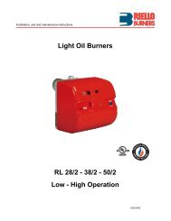
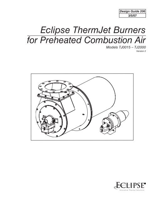
Introduction1ProductDescriptionThe <strong>ThermJet</strong> PCA (preheated combustion air) is a nozzle-mixburner designed to fire an intense stream of hot gases through acombustor using preheated combustion air temperatures up to1000° F. (Models TJPCA0500 through TJPCA1000 are rated <strong>for</strong>use with preheated combustion air temperatures up to 700° F.)The high velocity of the gases improves temperature uni<strong>for</strong>mity,product quality and system efficiency. <strong>ThermJet</strong> PCA burnersuse medium velocity TJ combustors providing velocities from250 ft/s to 750 ft/s depending on the temperature of the preheatedcombustion air.Figure 1.1 The <strong>ThermJet</strong> PCA Burner <strong>Eclipse</strong> <strong>ThermJet</strong> PCA Design Guide No. 206, 3/5/07
Safety2IntroductionSafetyImportant notices about safe burner operation will be found inthis section. Read this entire manual be<strong>for</strong>e attempting to startthe system. If any part of the in<strong>for</strong>mation in this manual is notunderstood, then contact your local <strong>Eclipse</strong> representative or<strong>Eclipse</strong> be<strong>for</strong>e continuing.Danger:The burners covered in this manual are designedto mix fuel with air and burn the resultingmixture. All fuel burning devices are capable ofproducing fires and explosions when improperlyapplied, installed, adjusted, controlled or maintained.Do not bypass any safety feature. Fires and explosionscan be caused.Never try to light the burner if the burner showssigns of damage or malfunctioning.Warning:The burner is likely to have HOT surfaces. Alwayswear protective clothing when approachingthe burner.Note:This manual gives in<strong>for</strong>mation <strong>for</strong> the use of these burners<strong>for</strong> their specific design purpose. Do not deviate from anyinstructions or application limits in this manual without writtenadvice from <strong>Eclipse</strong>.<strong>Eclipse</strong> <strong>ThermJet</strong> PCA Design Guide No. 206, 3/5/07
CapabilitiesOperator TrainingReplacement PartsWarning:<strong>Eclipse</strong> products are designed to minimize theuse of materials that contain crystalline silica.Examples of these chemicals are: respirablecrystalline silica from bricks, cement or othermasonry products and respirable refractoryceramic fibers from insulating blankets, boards,or gaskets. Despite these ef<strong>for</strong>ts, dust createdby sanding, sawing, grinding, cutting, and otherconstruction activities could release crystallinesilica. Crystalline silica is known to cause cancer,and health risks from the exposure to thesechemicals vary depending on the frequencyand length of exposure to these chemicals. Toreduce this risk, limit exposure to these chemicals,work in a well-ventilated area and wear approvedpersonal protective safety equipment <strong>for</strong>these chemicals.Adjustment, maintenance and troubleshooting of the mechanicaland the electrical parts of this system should be done by qualifiedpersonnel with good mechanical aptitude and experiencewith combustion equipment.The best safety precaution is an alert and competent operator.Thoroughly instruct new operators so they demonstratean adequate understanding of the equipment and its operation.Regular retraining must be scheduled to maintain a high degreeof proficiency.Order replacement parts from <strong>Eclipse</strong> only. Any customer-suppliedvalves or switches should carry UL, FM, CSA,CGA and/orCE approval where applicable. <strong>Eclipse</strong> <strong>ThermJet</strong> PCA Design Guide No. 206, 3/5/07
System Design3DesignDesign structureDesigning a burner system is a straight-<strong>for</strong>ward exercise ofcombining modules that add up to a reliable and safe system.The design process is divided into the following steps:1. Burner model selection:a. The burner size and quantityb. The fuel type and pressurec. The combustor material2. Control methodology3. Ignition system4. Flame monitoring system5. <strong>Combustion</strong> air system: blower and air pressure switch6. Main gas shut-off valve train selection7. Process temperature control systemStep 1: Burner modelselectionBurner size and quantitySelect the size and number of burners based on the heat balance.For heat balance calculations, refer to the <strong>Combustion</strong>Engineering Guide (EFE 825).Per<strong>for</strong>mance data, dimensions and specifications are given <strong>for</strong>each TJPCA model in Data Sheets 206-1 through 206-13Fuel type & fuel pressureThe usable fuel types are:• Natural gas• Propane• ButaneFor other fuels less than 800 Btu/ft (330 MJ/m3) contact <strong>Eclipse</strong>with an accurate breakdown of the fuel contents.The minimum gas pressure required at the burner can be foundin <strong>ThermJet</strong> PCA Data Sheets 206-1 through 206-13.<strong>Eclipse</strong> <strong>ThermJet</strong> PCA Design Guide No. 206, 3/5/07
Combustor MaterialThe combustor that you choose depends on the temperatureand the construction of the furnace. Each burner size comesin at least two materials (SiC is available on models up to0200TJPCA). Select material suitable <strong>for</strong> furnace and preheatedair temperature.The application temperature limits of the combustors can befound in <strong>ThermJet</strong> PCA Data Sheets 206-1 through 206-13The control methodology is the basis <strong>for</strong> the rest of the designprocess. Once it is known what the system will look like, thecomponents can be selected. The control methodology chosendepends on the type of process to be controlled. All methodsemploy a heat exchanger and eductor per zone.Step 2: Control MethodologyThere are four basic methods <strong>for</strong> preheated combustion airapplications. The methods depend on how furnace pressurecontrol and ratio control are applied:1.2.3.4.Furnace pressure control fixed at start up. Single diaphragmratio regulatorFurnace pressure control fixed at start up. Double diaphragmratio regulatorAutomatic furnace pressure control. Double diaphragmratio regulator.Automatic furnace pressure control. Electronic mass ratiocontrol.The recommended method to control the input of a <strong>ThermJet</strong>PCA burner system is modulating gas & air (on-ratio control orexcess air @ low fire). This method may be applied to singleburner as well as multiple burner systems:Note:The stated operational characteristics only apply if the describedcontrol circuits are followed. Use of different controlmethods will result in unknown operational per<strong>for</strong>mancecharacteristics. Use the control circuits contained within thissection or contact <strong>Eclipse</strong> <strong>for</strong> written, approved alternatives.10 <strong>Eclipse</strong> <strong>ThermJet</strong> PCA Design Guide No. 206, 3/5/07
Step 2: Control Methodology(continued)In the pages that follow you will find schematics of these controlmethods. The symbols in the schematics are explained in the“Key to System Schematics” (see Appendix).Automatic gas shut-off by burner or shut-off by zoneThe automatic gas shut-off valve can be installed in two operationalmodes:1.2.Automatic gas shut-off by burnerIf the flame monitoring system detects a failure, the gas shut-offvalves close the gas supply to the burner that caused the failure.Automatic gas shut-off by zoneIf the flame monitoring system detects a failure, the gas shutoffvalves close the gas supply to all the burners in the zonethat caused the failure.Note:All <strong>ThermJet</strong> PCA control schematics on the following pagesreflect a single gas automatic shut-off valve. Each schematicshows both operational modes. Only one is necessary.This may be changed to con<strong>for</strong>m to local safety and/or insurancerequirements (Refer to page 9 of <strong>ThermJet</strong> InstallationGuide No. 206).Modulating gas & airOn-ratio control or excess air @ low fireA burner system with modulating control gives an input thatis in proportion with the demands of the process. ANY inputbetween high and low fire is possible.1.2.<strong>Air</strong>The control valve 1 is in the air line. It can modulate airflow to any position between low and high fire air.GasThe ratio regulator 2 allows the on-ratio amount of gas togo to the burner. Low fire gas is limited by the ratio regulator2. High fire gas is limited by the manual butterfly valve3.Note:The ratio regulator can be biased to give excess air at low fireNote:Do not use an adjustable limiting orifice (ALO) as the highfire gas limiting valve 3. ALO’s require too much pressuredrop <strong>for</strong> use in a proportional system.<strong>Eclipse</strong> <strong>ThermJet</strong> PCA Design Guide No. 206, 3/5/0711
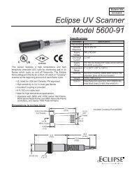
Step 2: ControlMethodology (continued)Figure 3.1➊Modulating gas & air.On-ratio control or excess air @ low fireEductor FlowControl ValveHeatExchanger/Eductorto other <strong>Burners</strong>Furnace pressure controlfixed at start up.Single diaphragm ratio regulator.Main gasshut-offvalve trainManual<strong>Combustion</strong><strong>Air</strong> ControlValve➋RatioRegulatorAutomaticshut-off byzone or by burnerNCNC➌to other <strong>Burners</strong>➊Eductor FlowControl ValveHeatExchanger/Eductorto other <strong>Burners</strong>Furnace pressure controlfixed at start up.Double diaphragm ratio regulator.Main gasshut-offvalve trainManual<strong>Combustion</strong><strong>Air</strong> ControlValve➋RatioRegulatorAutomaticshut-off byzone or by burnerNCNC➌to other <strong>Burners</strong>➊HeatExchanger/Eductorto other <strong>Burners</strong>Automatic Furnace pressure control.Double diaphragm ratio regulator.Main gasshut-offvalve train➋RatioRegulatorAutomaticshut-off byzone or by burnerNCNC➌to other <strong>Burners</strong>HeatExchanger➊to other <strong>Burners</strong>Automatic Furnace pressure control.Electronic mass ratio control.CAutomaticshut-off byzone or by burnerNCMain gasshut-offvalve trainCNC➌to other <strong>Burners</strong>12 <strong>Eclipse</strong> <strong>ThermJet</strong> PCA Design Guide No. 206, 3/5/07
Step 3: Ignition SystemFor the ignition system use:• 6,000 VAC trans<strong>for</strong>mer• Full-wave spark trans<strong>for</strong>mer• One trans<strong>for</strong>mer per burnerDO NOT USE:• 10,000 VAC trans<strong>for</strong>mer• Twin outlet trans<strong>for</strong>mer• Distributor type trans<strong>for</strong>mer• Half-wave trans<strong>for</strong>merIt is recommended that low fire start be used. However, <strong>ThermJet</strong>PCA burners are capable of direct spark ignition anywherewithin the specified ignition zone (see Data Sheets 206-1through 206-13).Note:You must follow the control circuits described in the previous section,“Control Methodology,” to obtain reliable ignition.Local safety and insurance require limits on the maximum trial<strong>for</strong> ignition time. These time limits vary from country to country.The time it takes <strong>for</strong> a burner to ignite depends on:• The distance between the gas shut-off valve and the burner• The air/gas ratio• The gas flow at start conditionsIt is possible to have the low fire too low to ignite within thetrial <strong>for</strong> ignition period. Under these circumstances you mustconsider the following options:•••Start at higher input levels.Resize and/or relocate the gas controls.Use bypass start gas. (See page 14)Bypass start gas (optional)A bypass start gas circuit provides gas flow around zone gasconrol valves during the trial <strong>for</strong> ignition period. This shouldonly be used if excess air is being used on low fire; it shouldNOT be used with on-ratio low fire systems. During the trial<strong>for</strong> ignition period, the solenoid valve in the bypass line plusthe automatic gas shut-off valve (either at each burner or eachzone) are opened. If a flame is established, the bypass solenoidvalve closes at the end of the trial <strong>for</strong> ignition period. If a flameis not established, then the bypass solenoid valve and the automaticgas shut-off valve close.(See page 14 <strong>for</strong> bypass start gas circuit schematic)<strong>Eclipse</strong> <strong>ThermJet</strong> PCA Design Guide No. 206, 3/5/0713
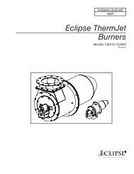
Figure 3.2 Bypass start gas circuit schematic➊HeatExchangerto other <strong>Burners</strong>Main gasshut-offvalve trainRatioRegulator➋Automaticshut-off byzone or by burnerNCNC➌to other <strong>Burners</strong>Bypass optionStep 4: Flame monitoringsystemA flame monitoring system consists of two main parts:• A flame sensor• Flame monitoring controlFlame sensorAll <strong>ThermJet</strong> PCA burners operate with UV Scanners only. AU.V. scanner can be used with all combustor types. Youcan find in<strong>for</strong>mation on U.V. scanners in these documents::••••Info Guide 852 <strong>for</strong> 90º U.V. scannersInfo Guide 854 <strong>for</strong> straight U.V. scannersInstruction Manual 855 <strong>for</strong> Solid State UV/IR scannersInfo Guide 856 <strong>for</strong> self-check U.V. scanner.sU.V. scannerNote:Ambient temperature limits <strong>for</strong> rhe scanners are likely to beexceeded. An insulated coupling, heat block seal or scannercooler may be required. See Bulletins 832 and 834.Flame Monitoring ControlThe flame monitoring control is the equipment that processesthe signal from the U.V. scanner.For flame monitoring control you may select several options:• Flame monitoring control <strong>for</strong> each burner: if one burnergoes down, only that burner will be shut off• Multiple burner flame monitoring control: if one burnergoes down, all burners will be shut offThere are three recommended flame monitoring controls:• Bi-flame series; see Instruction Manual 826• Multi-flame series 6000; see Instruction Manual 820• Veri-flame; see Instruction Manual 818Other manufacturer’s flame monitoring systems can be usedwith the burner if spark is maintained <strong>for</strong> a fixed time intervaland is not interrupted when a flame signal is detected duringtrial <strong>for</strong> ignition.14 <strong>Eclipse</strong> <strong>ThermJet</strong> PCA Design Guide No. 206, 3/5/07
Step 5: <strong>Combustion</strong><strong>Air</strong> System: Blower andair pressure switchEffects of atmospheric conditionsThe blower data is based on the International Standard Atmosphere(ISA) at Mean Sea Level (MSL), which means that it isvalid <strong>for</strong>:•••Sea level29.92” Hg (1,013 mbar)70ºF (21ºC)The make-up of the air is different. above sea level or in a hotarea. The density of the air decreases, and as a result, the outletpressure and the flow of the blower decrease. An accurate descriptionof these effects is in the <strong>Eclipse</strong> <strong>Combustion</strong> EngineeringGuide (EFE 825). The Guide contains tables to calculate theeffect of pressure, altitude and temperature on air.BlowerThe rating of the blower must match the system requirements.You can find all the blower data in Bulletin/Info Guide 610Follow these steps:1. Calculate the outlet pressure.<strong>Preheated</strong> <strong>Air</strong> Pressure DropCorrection FactorsIf combustion airtemperature is:400º F600º F800º F1000º FSeries SMJ turbo blowerMultiply60º F drop by:1.652.042.422.81Note:For a given combustion air flow, system pressure dropsincrease with air temperature. Multiply calculated cold airpressure drops by the appropriate factor in the chart at leftto arrive at the preheated air drop.When calculating the outlet pressure of the blower, the total ofthese pressures must be calculated.• The static air pressure required at the burner found in theburner Data Sheet, 206-1 to 206-13• The total pressure drop in the piping• The total of the pressure drops across the valves• The pressure in the chamber (suction or pressurized)<strong>Eclipse</strong> recommends a minimum safety margin of 10%2. Calculate the required flowThe blower output is the air flow delivered under standard atmosphericconditions. It must be enough to feed all the burnersin the system at high fire and provide the eductor flow.<strong>Combustion</strong> air blowers are normally rated in terms of standardcubic feet per hour (scfh) of air.An example calculation follows the in<strong>for</strong>mation tables.<strong>Eclipse</strong> <strong>ThermJet</strong> PCA Design Guide No. 206, 3/5/0715
Step 5: <strong>Combustion</strong> <strong>Air</strong>System: Blower and airpressure switch (continued)Table 3.1Required calculation in<strong>for</strong>mationTotal system heat input Btu/hr QNumber of burners - -Type of fuel - -Gross heating value of fuel Btu/ft 3 qDesired excess air percentage(typical excess air percentage@ high fire is 15%)<strong>Air</strong>/Gas ratio(Fuel specific, see table below)<strong>Air</strong> flowGas flowDESCRIPTION UNIT OF MEASURE FORMULA SYMBOLpercent %- ?scfhscfhV airV gasTable 3.2FUEL GASFuel gas heating valuesSTOICHIOMETRIC*GROSS HEATINGAIR/GAS RATIO? (ft 3 air /ft3 ) VALUEgasq (Btu/ft 3 )Natural gas(Birmingham, AL)9.41 1,002Propane 23.82 2,572Butane 30.47 3,225* Stoichiometric: No excess air. The precise amount of air and gas are present <strong>for</strong>complete combustion.Example BlowerCalculationApplication example:A batch furnace requires a gross heat input of 2,900,000 btu/hr.(based on anticipated 60% efficiency with preheated air). Thedesigner decides to provide the required heat input with fourburners operating on natural gas using 15% excess air.Calculation example:a. Decide which <strong>ThermJet</strong> PCA burner model is appropriate:Q (total heat input) of 2,900,000 btu/hr4 burners = 725,000 Btu/hr/burner• Select 4 Model TJ0075 <strong>ThermJet</strong> PCA burners based on therequired heat input of 725,000 Btu/hr <strong>for</strong> each burner.b. Calculate required gas flow:QV gas= q=2,9000,000 btu/hr1,002 Btu/ft 3 = 2,894 ft 3 /hr• Gas flow of 2,894 ft 3 /hr is required16 <strong>Eclipse</strong> <strong>ThermJet</strong> PCA Design Guide No. 206, 3/5/07
Example BlowerCalculation(Continued)Calculation example (Continued):c. Calculate required stoichiometric air flow:V air-Stoichiometric= α (air/gas ratio) x V gas= 9.41 x 2,894 ft 3 /hr= 27,235 ft 3 /hr• Stoichiometric air flow of 27,235 scfh requiredd. Calculate blower air flow requirement based on thedesired amout of excess air:V air= (1 V airexcess air %) x V air-Stoichiometric= (1 + 0.15 ) x 27,235 ft 3 /hr = 31,320 ft 3 /hre. Calculate eductor flow. For this example, eductor flow is40% of combustion air flow:V eductor= .4 x 31,320 ft 3 /hr = 12,528 ft 3 /hr• Final blower air flow requirement is the sum ofV air+ V eductor= 43,848 ft 3 /hr at 15% excess air.Note:It is common practice to add an additional 10% to the finalblower air flow requirement as a safety margin.2. Find the blower model number and motor horsepower (hp).With the output pressure and the specific flow, you can find theblower catalog number and the motor hp in Bulletin/Info Guide610.4. <strong>Eclipse</strong> <strong>Combustion</strong> recommends that you select a TotallyEnclosed Fan Cooled (TEFC) motor.5. Select the other parameters:• inlet filter or inlet grille• inlet size (frame size)• voltage, number of phases, frequency• blower outlet location, and rotation direction Clockwise(CW) or Counter Clockwise (CCW).<strong>Eclipse</strong> <strong>ThermJet</strong> PCA Design Guide No. 206, 3/5/0717
Step 5: <strong>Combustion</strong> <strong>Air</strong>System: Blower and airpressure switch (continued)Note:The use of an inlet air filter is strongly recommended. Thesystem will per<strong>for</strong>m longer and the settings will be morestable.Note:When selecting a 60 Hz Blower <strong>for</strong> use on 50 Hz, a pressureand capacity calculation is required. See <strong>Eclipse</strong> <strong>Combustion</strong>Engineering Guide (EFE 825).Inlet filter withreplaceable filterelementThe total selection in<strong>for</strong>mation you should now have:• Blower model number• Motor hp• Motor enclosure (TEFC)• Voltage, number of phases, frequency• Rotation direction (CW or CCW).<strong>Air</strong> pressure switchThe air pressure switch gives a signal to the monitoring systemwhen there is not enough air pressure from the blower.You can find more in<strong>for</strong>mation on pressure switches in BlowerBulletin 610Step 6: Main gas shut-offvalve trainMain gasshut-offvalve train<strong>Air</strong> pressure switchWarning:<strong>Eclipse</strong> supports NFPA regulations, which requirethe use of an air pressure switch in conjunctionwith other safety components, as a minimumstandard <strong>for</strong> main gas safety shut-off systems.Consult <strong>Eclipse</strong><strong>Eclipse</strong> can help you design and obtain a main gas shut-off valvetrain that complies with the current safety standards.The shut-off valve train must comply with all the local safetystandards set by the authorities that have jurisdiction.For details, please contact your local <strong>Eclipse</strong> representative orthe <strong>Eclipse</strong> factory.Note<strong>Eclipse</strong> supports NFPA regulations (two shut-off valves) as aminimum standard <strong>for</strong> main gas safety shut-off systems.Step 7: Process TemperatureControl SystemConsult <strong>Eclipse</strong>The process temperature control system is used to control andmonitor the temperature of the system. There is a wide varietyof control and measuring equipment available.For details, please contact your local <strong>Eclipse</strong> representative orthe <strong>Eclipse</strong> factory.18 <strong>Eclipse</strong> <strong>ThermJet</strong> PCA Design Guide No. 206, 3/5/07
AppendixConversionFactorsMetric to English.FROM TO MULTIPLY BYcubic meter (m 3 ) cubic foot (ft 3 ) 35.31cubic meter/hour (m 3 /h) cubic foot/hour (cfh) 35.31degrees Celsius (°C) degrees Fahrenheit (°F) (°C x 1.8) + 32kilogram (kg) pound (lb) 2.205kilowatt (kW) Btu/hr 3414meter (m) foot (ft) 3.28millibar (mbar) inches water column (“wc) 0.401millibar (mbar) pounds/sq in (psi) 14.5 x 10 -3millimeter (mm) inch (in) 3.94 x 10 -2Metric to Metric.FROM TO MULTIPLY BYkiloPascals (kPa) millibar (mbar) 10meter (m) millimeter (mm) 1000millibar (mbar) kiloPascals (kPa) 0.1millimeter (mm) meter (m) 0.001English to Metric.FROM TO MULTIPLY BYBtu/hr kilowatt (kW) 0.293 x 10 -3cubic foot (ft 3 ) cubic meter (m 3 ) 2.832 x 10 -2cubic foot/hour (cfh) cubic meter/hour (m 3 /h) 2.832 x 10 -2degrees Fahrenheit (°F) degrees Celsius (°C) (°F – 32) ÷ 1.8foot (ft) meter (m) 0.3048inches (in) millimeter (mm) 25.4inches water column (“wc) millibar (mbar) 2.49pound (lb) kilogram (kg) 0.454pounds/sq in (psi) millibar (mbar) 68.95<strong>Eclipse</strong> <strong>ThermJet</strong> PCA Design Guide No. 206, 3/5/0719
Key to system schematicsSYMBOL APPEARANCE NAME REMARKSBULLETIN/INFO GUIDE<strong>ThermJet</strong> burnerMain gasshut-offvalve trainMain gas shutoff valve train<strong>Eclipse</strong>, Inc. strongly endorsesNFPA as a minimum.756<strong>Combustion</strong> air blowerThe combustion air blowerprovides the combustion airpressure to the burner (s).610P<strong>Air</strong> pressure switchThe air pressure switch givesa signal to the safety systemwhen there is not enough airpressure from the blower.610NCGas cockSolenoid valve(normally closed)Gas cocks are used to manuallyshut off the gas supply on bothsides of the main gas shut-offvalve train.Solenoid valves are used toautomatically shut off the gassupply on a bypass gas system oron small capacity burner systems.710760Manual butterfly valveManual butterfly valves are usedto balance the air or gas flow ateach burner, and/or to control thezone flow.720Automatic butterfly valveAutomatic butterfly valves aretypically used to set the output ofthe system.72020 <strong>Eclipse</strong> <strong>ThermJet</strong> PCA Design Guide No. 206, 3/5/07
Key to System Schematics (Continued)SYMBOL APPEARANCE NAME REMARKSBULLETIN/INFO GUIDERatio regulatorA ratio regulator is used tocontrol the air/gas ratio. Theratio regulator is a sealed unitthat adjusts the gas flow in ratioto the air flow.742ControllerA controller senses pressure andcontrols flow.CCRS valveA CRS valve is used in a high/low time-proportional controlsystem to quickly open and closethe air supply.744Pressure tapsThe schematics show the advisedpositions of the pressure taps.Impulse lineThe impulse line connects theratios regulator to the air supplyline.Heat Exchanger/EductorThe heat exchanger/eductorrecovers wast heat fromindustrial exhaust gases. Therecovered heat is used topreheat combustion air <strong>for</strong>the systems burners, therebyincreasing fuel efficiency.<strong>Eclipse</strong> <strong>ThermJet</strong> PCA Design Guide No. 206, 3/5/0721