

Boiler Manual - Weil-McLain
Boiler Manual - Weil-McLain
Boiler Manual - Weil-McLain

You also want an ePaper? Increase the reach of your titles
YUMPU automatically turns print PDFs into web optimized ePapers that Google loves.
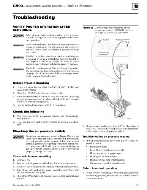
GV90+ gas-fired water boiler — <strong>Boiler</strong> <strong>Manual</strong>TroubleshootingVERIFY PROPER OPERATION AFTERSERVICING.Label all wires prior to disconnection when servicingcontrols. Wiring errors can cause improper and dangerousoperation.Never jumper (bypass) any device except for momentarytesting as outlined in Troubleshooting charts. Severepersonal injury, death or substantial property damagecan result.The IBC and boiler controls can malfunction if they getwet. Never try to use a control that has been flooded orwet. Replace it. Failure to comply can result in severepersonal injury, death or substantial property damage.The boiler contains ceramic fiber and fiberglass materials.Use care when handling these materials per instructionson page 107 of this manual. Failure to comply couldresult in severe personal injury.Figure 85 Connecting a manometer to checkair pressure switch. DO NOT use thisarrangement to check gas valveBefore troubleshooting1. Have a voltmeter that can check 120 VAC, 24 VAC, 24 VDC anda continuity checker.2. Check for 120 VAC (min. 102-max.132) to boiler.3. Make sure thermostat is calling for heat and contacts (includingappropriate zone controls) are closed. Check for 24 VAC betweenthermostat wire nuts and ground.4. Have an inclined manometer with 0 – 2” w.c. range.Check the following1. Wire connectors to IBC are securely plugged in at IBC and originatingcontrol.2. Hoses are properly and securely plugged in and are not damaged.Checking the air pressure switchDo not use manometer as shown in Figure 85 to test gasvalve outlet pressure. Where instructed in this manualto check gas valve outlet pressure, follow instructionscarefully, particularly regarding connection of manometer.Manometer fluid will cause permanent damage togas valve. Severe personal injury, death or substantialproperty damage can result.Check switch pressure setting1. See Figure 85.2. Remove both air pressure switch hoses from air pressure switch.3. Install tees and tubing as shown in Figure 85 to inclined manometer.4. Turn off gas valve and set thermostat to call for heat. Blower willrun but burner will not ignite.5. Check for 24 VAC between both air pressure switch terminals andground.6. If manometer reading is at least 1.0” w.c., but there isnot 24 VAC between both air pressure switch terminalsand ground, replace air pressure switch.Troubleshooting air pressure reading1. If manometer reading is lower than 1.4” w.c. check forpossible causes:• Blockage in hoses.• Loose blower wheel on motor shaft.• Blower motor not at proper rpm.• Blockage in air inlet or hose.• Blockage in flue pipe or termination.• Condensate trap filled w/condensate.Return to normal operation1. When pressure reading is proper and air pressure switchis operating properly, remove tees and reinstall hoses toair pressure switch.Part number 550-142-054/1211 75


