

Boiler Manual - Weil-McLain
Boiler Manual - Weil-McLain
Boiler Manual - Weil-McLain

Create successful ePaper yourself
Turn your PDF publications into a flip-book with our unique Google optimized e-Paper software.
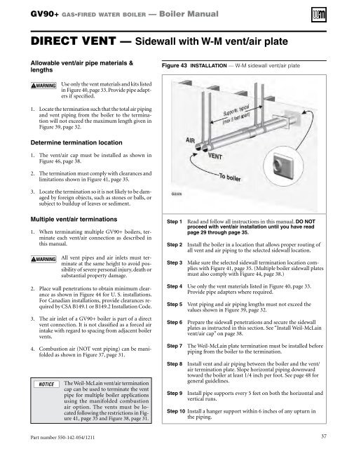
GV90+ gas-fired water boiler — <strong>Boiler</strong> <strong>Manual</strong>DIRECT VENT — Sidewall with W-M vent/air plateAllowable vent/air pipe materials &lengthsFigure 43 Installation — W-M sidewall vent/air plateUse only the vent materials and kits listedin Figure 40, page 33. Provide pipe adaptersif specified.1. Locate the termination such that the total air pipingand vent piping from the boiler to the terminationwill not exceed the maximum length given inFigure 39, page 32.Determine termination location1. The vent/air cap must be installed as shown inFigure 46, page 38.2. The termination must comply with clearances andlimitations shown in Figure 41, page 35.3. Locate the termination so it is not likely to be damagedby foreign objects, such as stones or balls, orsubject to buildup of leaves or sediment.Multiple vent/air terminations1. When terminating multiple GV90+ boilers, terminateeach vent/air connection as described inthis manual.All vent pipes and air inlets must terminateat the same height to avoid possibilityof severe personal injury, death orsubstantial property damage.2. Place wall penetrations to obtain minimum clearanceas shown in Figure 44 for U. S. installations.For Canadian installations, provide clearances requiredby CSA B149.1 or B149.2 Installation Code.3. The air inlet of a GV90+ boiler is part of a directvent connection. It is not classified as a forced airintake with regard to spacing from adjacent boilervents.4. Combustion air (NOT vent piping) can be manifoldedas shown in Figure 37, page 31.The <strong>Weil</strong>-<strong>McLain</strong> vent/air terminationcap can be used to terminate the ventpipe for multiple boiler applicationsusing the manifolded combustionair option. The vents must be locatedfollowing the restrictions in Figure41, page 35 and Figure 38, page 31.Step 1 Read and follow all instructions in this manual. DO NOTproceed with vent/air installation until you have readpage 29 through page 35.Step 2 Install the boiler in a location that allows proper routing ofall vent and air piping to the selected sidewall location.Step 3 Make sure the selected sidewall termination location complieswith Figure 41, page 35. (Multiple boiler sidewall platesmust also comply with Figure 44, page 38.)Step 4 Use only the vent materials listed in Figure 40, page 33.Provide pipe adapters where required.Step 5 Vent piping and air piping lengths must not exceed thevalues shown in Figure 39, page 32.Step 6 Prepare the sidewall penetrations and secure the sidewallplates as instructed in this section. See “Install <strong>Weil</strong>-<strong>McLain</strong>vent/air cap” on page 38.Step 7 The <strong>Weil</strong>-<strong>McLain</strong> plate termination must be installed beforepiping from the boiler to the termination.Step 8 Install vent and air piping between the boiler and the vent/air termination plate. Slope horizontal piping downwardtoward the boiler at least 1/4 inch per foot. See page 48 forgeneral guidelines.Step 9 Install pipe supports every 5 feet on both the horizontal andvertical runs.Step 10 Install a hanger support within 6 inches of any upturn inthe piping.Part number 550-142-054/1211 37


