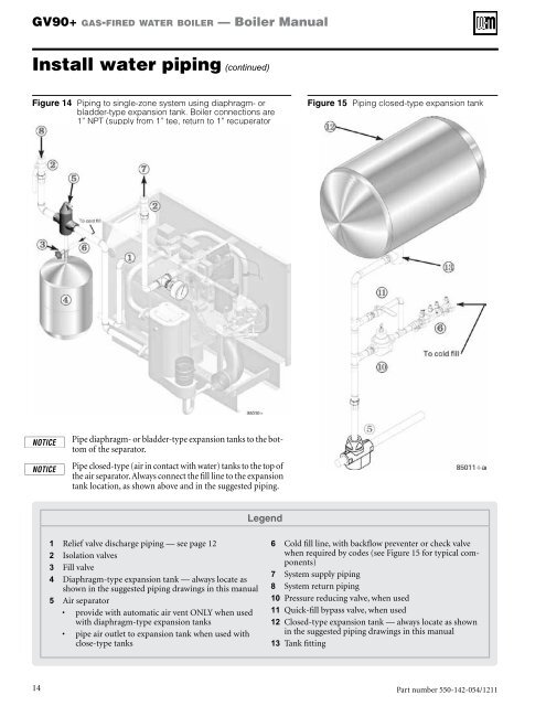
GV90+ gas-fired water boiler — <strong>Boiler</strong> <strong>Manual</strong>Install water piping (continued)Figure 14 Piping to single-zone system using diaphragm- orbladder-type expansion tank. <strong>Boiler</strong> connections are1” NPT (supply from 1” tee, return to 1” recuperatorflange).Figure 15 Piping closed-type expansion tankPipe diaphragm- or bladder-type expansion tanks to the bottomof the separator.Pipe closed-type (air in contact with water) tanks to the top ofthe air separator. Always connect the fill line to the expansiontank location, as shown above and in the suggested piping.Legend1 Relief valve discharge piping — see page 122 Isolation valves3 Fill valve4 Diaphragm-type expansion tank — always locate asshown in the suggested piping drawings in this manual5 Air separator• provide with automatic air vent ONLY when usedwith diaphragm-type expansion tanks• pipe air outlet to expansion tank when used withclose-type tanks6 Cold fill line, with backflow preventer or check valvewhen required by codes (see Figure 15 for typical components)7 System supply piping8 System return piping10 Pressure reducing valve, when used11 Quick-fill bypass valve, when used12 Closed-type expansion tank — always locate as shownin the suggested piping drawings in this manual13 Tank fitting14Part number 550-142-054/1211
GV90+ gas-fired water boiler — <strong>Boiler</strong> <strong>Manual</strong>Install water piping (continued)System water piping methodsCirculatorsMost piping methods shown in this manual useprimary/secondary connection to the boiler loop.These designs ensure proper flow through theGV90+ boiler, for the most efficient and reliableoperation of the boiler and the heating system.For other piping methods, consult your local <strong>Weil</strong>-<strong>McLain</strong> representative.Do not remove either of the GV90+ internal pumpsfor use elsewhere in the system. Both pumps arerequired for proper operation. Removing a pumpwill cause the boiler to malfunction. Substantialproperty damage could result.Never install another pump in series with theGV90+ boiler. Forced flow can cause improper operationof the boiler controls. Substantial propertydamage could result.Failure to comply could result in unreliable performanceand nuisance shutdowns from insufficientflow.Circulator flow rateSize system circulators based on the flow rate required to achievethe temperature change needed. You can closely estimate temperaturerise (or drop) through a circuit by using the followingformula, where TD is temperature rise (or drop), FLOW is flowrate (in gpm), and BTUH is the heat load for the circuit:BTUHFLOW = —–—–—–—–TD x 500Examples:Consider a system loop for a system with total heating load equalto 210,000 Btuh. The desired temperature drop through the systempiping is 20°F. Then the required flow rate is:FLOW =210,000—–—–—–—–20 x 500= 21 gpmSIMPLIFIED: For 20° temperature drop, FLOW = MBH / 10.Circulator head requirementThe circulator must be capable of delivering the required flowagainst the head loss that will occur in the piping. Determinethe pipe size needed and the resultant head loss using acceptedengineering methods. The simplified pipe sizing here is limitedto residential systems, and does not include systems with fan coilunits or radiant tubing.The following simplified method for pipe and circulatorsizing must be limited to residential applicationsusing baseboard (finned or cast iron), cast ironradiators or convectors. DO NOT apply for radiantheating, fan coil units or commercial installations.Simplified pipe/circulator selection1. Install the boiler and piping using the recommended pipinglayouts in this manual.2. Size the piping and components for each circuit in the spaceheating system using Figure 16. At the flow rates listed, thehead loss in all piping will be 0.04 feet per foot of pipe.a. Determine the heating load (Btuh) for each circuit.b. Calculate the flow rate for each circuit using its load.To use a 20°F temperature drop, just divide theMBH (1,000’s of Btuh) by 10.Example — Flow for 20°F temp drop with 35,000Btuh:FLOW = 35 MBH / 10 = 3.5 gpmc. Find the pipe size in Figure 16 that has a max flow ratejust larger than that required for the circuit.d. Find the total equivalent length (TEL) of the circuit.TEL accounts for losses through fittings and valves byusing the equivalent length of pipe that would causethe same head loss. Add these numbers to the measuredlength of the circuit to find TEL in feet.TEL is usually close to 1.5 times the length of thecircuit for residential baseboard, radiator or convectorapplications.e. Measure the length of each circuit from the circulatoroutlet back to its inlet. Then multiply this length times1.5 to get the approximate TEL of the circuit.f. Find the head loss for each circuit:TEL = 1.5 X Circuit Length (feet)HEAD = TEL X 0.04 (feet water column)g. NOTE: Size system header piping for the total flow ofall connected zones.3. Example:a. For a circuit with heating load = 45,000 Btuh (= 45MBH). Measured length of circuit is 88 feet.b. Flow = 45 MBH / 10 = 4.5 gpm.c. TEL = 1.5 x 88 feet = 132 feet.d. From Figure 16, select 1" pipe (max flow = 8 gpm).e. Head loss = TEL x 0.04 = 132 x 0.04 = 5.28 feet.f. Select a circulator that can deliver at least 4.5 gpm at ahead of 5.28 feet. (Read the NOTICE below.)To use this method, limit the flow through ¾"finned-tube baseboard to 3.9 gpm, or use 1" baseboardand limit flow to 7.1 gpm. If the total loadof the circuit requires more flow, split the circuitinto two or more.Figure 16 Flow rates for 0.04 feet head loss per foot ofcopper pipe (based on water at140°F)Pipe size(inches)MAX Flow rate (GPM)@ 0.04 feet per footPipe size(inches)MAX Flow rate (GPM)@ 0.04 feet per foot¾ 4 2 451 8 2½ 751¼ 14 3 1401½ 22 4 290Part number 550-142-054/1211 15