Users Guide for the Non-Inverted LM3875 Kit - DIY Audio Projects
Users Guide for the Non-Inverted LM3875 Kit - DIY Audio Projects
Users Guide for the Non-Inverted LM3875 Kit - DIY Audio Projects
- No tags were found...

You also want an ePaper? Increase the reach of your titles
YUMPU automatically turns print PDFs into web optimized ePapers that Google loves.
<strong>Users</strong> <strong>Guide</strong> <strong>for</strong> <strong>the</strong> <strong>Non</strong>-<strong>Inverted</strong> <strong>LM3875</strong> <strong>Kit</strong> Written by Brian Bell and Sandy H. 1 (26)<strong>Users</strong> <strong>Guide</strong> <strong>for</strong> <strong>the</strong> <strong>Non</strong>-<strong>Inverted</strong> <strong>LM3875</strong> <strong>Kit</strong>(also known as <strong>the</strong> Gainclone kit)1 INTRODUCTION.......................................................................................................................................... 21.1 HISTORY ................................................................................................................................................... 31.2 TERMINOLOGY USED IN THIS DOCUMENT................................................................................................. 42 BUILDING INSTRUCTIONS FOR THE KIT ........................................................................................... 52.1 PREMIUM KIT CONTENTS ......................................................................................................................... 52.2 BASIC KIT CONTENTS............................................................................................................................... 52.3 SOLDERING TIPS ....................................................................................................................................... 62.4 ASSEMBLING THE AMPLIFIER PCB........................................................................................................... 72.5 ASSEMBLING THE RECTIFIER PCB ......................................................................................................... 132.6 PICTURE OF FINISHED PCBS ................................................................................................................... 143 HOW TO TURN THE ASSEMBLED KIT INTO A WORKING AMPLIFIER................................... 153.1 CHOOSING A TRANSFORMER .................................................................................................................. 153.2 WIRING THE POWER SUPPLY AND INSTALLING INTO THE CHASSIS......................................................... 173.3 CHASSIS CONSIDERATIONS .................................................................................................................... 213.4 VOLUME CONTROL................................................................................................................................. 224 MISCELLANEOUS INFORMATION ...................................................................................................... 234.1 THE ZOBEL NETWORK............................................................................................................................ 234.2 THE BRIDGED <strong>LM3875</strong>........................................................................................................................... 234.3 AN INPUT BUFFER .................................................................................................................................. 245 FREQUENTLY ASKED QUESTIONS (FAQ) ......................................................................................... 255.1 WHAT STARTED THIS GROUP ORDER? .................................................................................................... 255.2 WHERE DID YOU FIRST FIND OUT ABOUT THE GAINCLONE?................................................................... 255.3 I JUST ORDERED THE PCB SET, WHAT PREMIUM COMPONENTS SHOULD I USE WITH IT? ....................... 265.4 I WOULD RATHER START WITH BASIC COMPONENTS, WHAT WORKS WITH THE BOARD? ....................... 265.5 I HAVE A SUGGESTION FOR MATERIAL TO BE ADDED TO THIS MANUAL................................................. 26
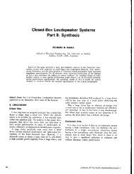
<strong>Users</strong> <strong>Guide</strong> <strong>for</strong> <strong>the</strong> <strong>Non</strong>-<strong>Inverted</strong> <strong>LM3875</strong> <strong>Kit</strong> Written by Brian Bell and Sandy H. 2 (26)Picture of Rev A PCB set1 IntroductionPicture of Rev B PCB setThanks <strong>for</strong> participating in <strong>the</strong> <strong>Non</strong>-<strong>Inverted</strong> <strong>LM3875</strong> kit/PCB group order. The goal ofthis kit is to get easy to build, good sounding <strong>DIY</strong> amplifiers into <strong>the</strong> hands of as manypeople as possible. I am tired of seeing countless people start projects and never finish<strong>the</strong>m. I have done this myself, but this kit should be simple enough to build, that youshouldn’t have an excuse <strong>for</strong> not finishing it in a reasonable amount of time.
<strong>Users</strong> <strong>Guide</strong> <strong>for</strong> <strong>the</strong> <strong>Non</strong>-<strong>Inverted</strong> <strong>LM3875</strong> <strong>Kit</strong> Written by Brian Bell and Sandy H. 3 (26)1.1 HistoryIt should be noted that <strong>the</strong> currently available kit uses a Rev B board. Additions to thisboard have been taken from feedback from those who purchased <strong>the</strong> Rev A boards, aswell as <strong>the</strong> design guidance from members of <strong>the</strong> diy<strong>Audio</strong>.com community. Majorchanges to <strong>the</strong> Rev B board include <strong>the</strong> addition of a second rectifier board, allowing<strong>the</strong> construction of true monoblok amplifiers without purchasing additional boards, <strong>the</strong>ability to mount <strong>the</strong> feedback resistor on <strong>the</strong> PCB directly and an area <strong>for</strong> a Zobelnetwork to be integrated directly on <strong>the</strong> board. Most of <strong>the</strong> pictures contained in thisdocument are of <strong>the</strong> Rev A board, but changes where pertinent are included <strong>for</strong> <strong>the</strong>Rev B board. A comparison is shown on <strong>the</strong> previous page of <strong>the</strong> 2 boards.The term gainclone is based on <strong>the</strong> 47 Laboratory 4706 Gaincard. After rave reviewsof this amplifier in Japan, it was determined that <strong>the</strong> main component of this amplifierwas a readily available $5 chip, made by National Semiconductor. This chip, <strong>the</strong><strong>LM3875</strong>, when properly implemented creates a high quality amplifier. This started anew trend in <strong>DIY</strong> amplifiers, as this is <strong>the</strong> first time that such a high quality amplifiercould be made so easily and <strong>for</strong> such little money.
<strong>Users</strong> <strong>Guide</strong> <strong>for</strong> <strong>the</strong> <strong>Non</strong>-<strong>Inverted</strong> <strong>LM3875</strong> <strong>Kit</strong> Written by Brian Bell and Sandy H. 4 (26)1.2 Terminology used in this document<strong>Non</strong>-Inverting – Operational Amplifier (opamp) topology used in this kit. An opamphas 2 input terminals. If <strong>the</strong> input goes into <strong>the</strong> +input, <strong>the</strong>n it is generally non-inverting,meaning that <strong>the</strong> output is in phase with <strong>the</strong> input.Negative Feedback (NFB) – A technique used in most power amplifiers to set <strong>the</strong>voltage gain. The output is fed back into <strong>the</strong> negative input on <strong>the</strong> amplifier. The effectof negative feedback is to cancel out distortion and negate <strong>the</strong> effect from non-idealcharacteristics. The NFB loop should be as short as possible. This leads to <strong>the</strong> NFBresistor not being placed on <strong>the</strong> PCB, and soldered directly to <strong>the</strong> device pins. On <strong>the</strong>Rev B board, <strong>the</strong> option of including <strong>the</strong> NFB resistor is included, but not required and<strong>the</strong> builder is encouraged to still solder <strong>the</strong> NFB directly as described in <strong>the</strong> followinginstructions.<strong>LM3875</strong> – Amplifier IC used in this kit. It is available in 2 different packages, insulated<strong>LM3875</strong>TF, and un-insulated <strong>LM3875</strong>T. The insulated package is usually preferred,due to <strong>the</strong> ease of use. Some people say that <strong>the</strong> insulated package also soundsbetter. The actual Gaincard uses <strong>the</strong> <strong>LM3875</strong>TF.PCB – abbreviation <strong>for</strong> printed circuit boardGain – Ratio of output divided by Input, expressed by:Av=vvoutinGainclone – Amplifier using a chip amplifier, such as <strong>the</strong> <strong>LM3875</strong> used in this amplifier
<strong>Users</strong> <strong>Guide</strong> <strong>for</strong> <strong>the</strong> <strong>Non</strong>-<strong>Inverted</strong> <strong>LM3875</strong> <strong>Kit</strong> Written by Brian Bell and Sandy H. 5 (26)2 Building Instructions <strong>for</strong> <strong>the</strong> <strong>Kit</strong>2.1 Premium <strong>Kit</strong> ContentsDescriptionQuantityPCB containing board <strong>for</strong> 2 channels and 2 rectifiers 1<strong>LM3875</strong>TF – National Semiconductor chip amplifier 21500uF 50v – Panasonic FC Capacitor 422k ohm – Caddock MK132 resistor (R 2 and R NFB ) 4680 ohm – Riken Ohm 0.5w resistor (R 3 ) 2220 ohm – Caddock MK132 resistor (R 1 ) 2MUR860 – On Semiconductor fast diode 84.7uF 50v – Black Gate N-type capacitor 22.2 Basic <strong>Kit</strong> ContentsDescriptionQuantityPCB containing board <strong>for</strong> 2 channels and 2 rectifiers 1<strong>LM3875</strong>TF - National Semiconductor chip amplifier 21500uF 50v - Panasonic FC Capacitor 422k ohm – Phoenix SFR16S resistor (R 2 and R NFB ) 4680 ohm – Panasonic Carbon Film 0.5w resistor (R 3 ) 2220 ohm - Phoenix SFR16S resistor (R 1 ) 2MUR860 - On Semiconductor fast diode 84.7uF 100v – Panasonic FC capacitor 2The PCB <strong>for</strong> this project is scored, so it will easily break apart in to <strong>the</strong> boards required<strong>for</strong> a 2-channel stereo amplifier.
<strong>Users</strong> <strong>Guide</strong> <strong>for</strong> <strong>the</strong> <strong>Non</strong>-<strong>Inverted</strong> <strong>LM3875</strong> <strong>Kit</strong> Written by Brian Bell and Sandy H. 6 (26)2.3 Soldering Tips(You are welcome to skip this section if you know how to solder)My recommendation, if you have never soldered be<strong>for</strong>e, is to find a friend to teach you,as experiencing it first hand would be <strong>the</strong> best way to learn. It is important to have adecent soldering iron, as you don’t want one that gets too hot or not hot enough. If yoursoldering iron is too hot, it can ruin <strong>the</strong> components on <strong>the</strong> boards, so if you are usingan unregulated iron, I would not exceed 30 watts. I like to use a regulated WellerWPTCT soldering iron, but it can be a ra<strong>the</strong>r expensive purchase if you won’t besoldering a lot. Also make sure that your iron gets hot enough, as cold solder jointscause bad connections.Recommended soldering procedure:1. Simultaneously apply <strong>the</strong> tip of <strong>the</strong> iron and <strong>the</strong> solder to <strong>the</strong> circuit board so that<strong>the</strong>y touch both each o<strong>the</strong>r and <strong>the</strong> wire being soldered to <strong>the</strong> solder pad.(working on <strong>the</strong> bottom side of <strong>the</strong> board)2. When <strong>the</strong> solder begins to flow, remove <strong>the</strong> solder and hold <strong>the</strong> iron on <strong>the</strong> jointuntil <strong>the</strong> solder flows and bonds to <strong>the</strong> wire and <strong>the</strong> pad.3. Pull <strong>the</strong> tip of <strong>the</strong> iron up so that it slides up <strong>the</strong> wire, leaving a nice smoothsoldering joint.4. Next, you will want to cut <strong>the</strong> excess wire off. Be sure to trim <strong>the</strong> wire just above<strong>the</strong> solder joint. You do not want to cut into <strong>the</strong> solder joint.Here is a picture that I found on <strong>the</strong> web of a good soldering joint, and 2 bad ones:Additional tips:From Peter Daniel: Liquid rosin flux might also work well. For anything that didn’tcome out nicely, you can touch with a brush wetted in flux and touch with <strong>the</strong> solderingiron. This will make it look nicer and remove any solder excess.From Sandy: If mistakes are made, or too much solder is used, desoldering braid is avery helpful tool. Simply hold <strong>the</strong> desoldering braid up to <strong>the</strong> soldered joint, and applyheat with <strong>the</strong> iron <strong>for</strong> removing unwanted solder. I prefer to use flux along with this tomake <strong>the</strong> process go more smoothly.
<strong>Users</strong> <strong>Guide</strong> <strong>for</strong> <strong>the</strong> <strong>Non</strong>-<strong>Inverted</strong> <strong>LM3875</strong> <strong>Kit</strong> Written by Brian Bell and Sandy H. 7 (26)2.4 Assembling <strong>the</strong> Amplifier PCBThere are a total of 6 components to be soldered to <strong>the</strong> PCB (3 resistors, 2 capacitorsand one <strong>LM3875</strong>), and one resistor to be soldered directly to <strong>the</strong> pins on <strong>the</strong> <strong>LM3875</strong> orto <strong>the</strong> PCB when using <strong>the</strong> Rev B boards. Here is <strong>the</strong> recommended procedure <strong>for</strong>putting <strong>the</strong> PCB toge<strong>the</strong>r:1. Since R 3 has <strong>the</strong> lowest profile on <strong>the</strong> PCB, start with this component first, following<strong>the</strong> soldering process detailed above.
<strong>Users</strong> <strong>Guide</strong> <strong>for</strong> <strong>the</strong> <strong>Non</strong>-<strong>Inverted</strong> <strong>LM3875</strong> <strong>Kit</strong> Written by Brian Bell and Sandy H. 8 (26)2. Next, solder R 1 and R 2 onto <strong>the</strong> pcb:3. The PCB should now look like this:
<strong>Users</strong> <strong>Guide</strong> <strong>for</strong> <strong>the</strong> <strong>Non</strong>-<strong>Inverted</strong> <strong>LM3875</strong> <strong>Kit</strong> Written by Brian Bell and Sandy H. 9 (26)4. Next, install <strong>the</strong> capacitors C1 and C2 (not labeled on PCB) using <strong>the</strong> correctpolarity as noted by <strong>the</strong> ‘+’ on <strong>the</strong> board. Note that <strong>the</strong>re are three holes instead oftwo due to optional capacitors having different lead spacing. Use one negative andone positive hole which fits <strong>the</strong> capacitor being used.
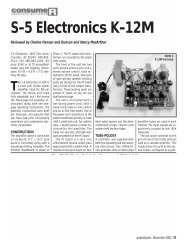
<strong>Users</strong> <strong>Guide</strong> <strong>for</strong> <strong>the</strong> <strong>Non</strong>-<strong>Inverted</strong> <strong>LM3875</strong> <strong>Kit</strong> Written by Brian Bell and Sandy H. 10 (26)5. The next step is to connect <strong>the</strong> negative feedback resistor (NFB), R NFB . Thisresistor may not placed on <strong>the</strong> PCB, as it is <strong>the</strong> most important component in thisamplifier, and <strong>the</strong> shortest possible signal path <strong>for</strong> this component will result in <strong>the</strong>best possible per<strong>for</strong>mance of <strong>the</strong> amplifier. For <strong>the</strong> Rev B boards, <strong>the</strong> option ofinstalling this resistor in <strong>the</strong> board is available, but direct connection is stillrecommended. There are two options <strong>for</strong> attaching <strong>the</strong> NFB resistor directly, placeit directly on <strong>the</strong> <strong>LM3875</strong> package, or install it on <strong>the</strong> underside of <strong>the</strong> PCB,connecting to <strong>the</strong> leads of <strong>the</strong> <strong>LM3875</strong> protruding through <strong>the</strong> PCB. The resistor,R NFB is connected from pin 3 to pin 8. The first method is more difficult, butprovides a shorter signal path. Beginners may way to stick to <strong>the</strong> second methodor to attaching it on <strong>the</strong> Rev B PCB. Here are pictures of how I attached <strong>the</strong>resistor to <strong>the</strong> <strong>LM3875</strong>:Attaching <strong>the</strong> resistor to <strong>the</strong> <strong>LM3875</strong>As you can see, I used a clamp to hold <strong>the</strong> resistor to <strong>the</strong> <strong>LM3875</strong>, while I solderedit to <strong>the</strong> package. A normal alligator clip will work fine <strong>for</strong> this.
<strong>Users</strong> <strong>Guide</strong> <strong>for</strong> <strong>the</strong> <strong>Non</strong>-<strong>Inverted</strong> <strong>LM3875</strong> <strong>Kit</strong> Written by Brian Bell and Sandy H. 11 (26)I had my fiancé put a board toge<strong>the</strong>r. She had never soldered be<strong>for</strong>e, and had noproblem getting <strong>the</strong> board assembled correctly. I had her solder <strong>the</strong> RNFB resistordirectly to <strong>the</strong> bottom of <strong>the</strong> PCB. Here is a picture of her board:The components used in <strong>the</strong> picture above are less expensive components, but <strong>the</strong>build process is <strong>the</strong> same. Soldering <strong>the</strong> resistor to <strong>the</strong> bottom of <strong>the</strong> board orattaching in <strong>the</strong> Rev B board will be easiest <strong>for</strong> most beginners.
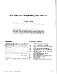
<strong>Users</strong> <strong>Guide</strong> <strong>for</strong> <strong>the</strong> <strong>Non</strong>-<strong>Inverted</strong> <strong>LM3875</strong> <strong>Kit</strong> Written by Brian Bell and Sandy H. 12 (26)6. The next step is to solder <strong>the</strong> <strong>LM3875</strong> to <strong>the</strong> board. On <strong>the</strong> PCB, pin 9 is a bitsmaller than <strong>the</strong> rest of <strong>the</strong> holes. This is an unused pin on <strong>the</strong> <strong>LM3875</strong>, which willbe used to make <strong>the</strong> soldering process easier <strong>for</strong> <strong>the</strong> <strong>LM3875</strong>, by holding <strong>the</strong> chipin place while it is being soldered. The plating was also removed so that <strong>the</strong>re wasmore clearance <strong>for</strong> <strong>the</strong> trace running next to <strong>the</strong> hole (+input trace).Insert <strong>the</strong> <strong>LM3875</strong> IC into <strong>the</strong> PCB, applying pressure on pin 9. Pin 9 will be a tightfit, but will help position <strong>the</strong> chip properly. Keep <strong>the</strong> chip elevated a bit from <strong>the</strong>board. Here is a picture:With <strong>the</strong> board upside down, supported by <strong>the</strong> capacitors as shown above, solder<strong>the</strong> <strong>LM3875</strong> into place.7. Your board should now be finished and look like this:
<strong>Users</strong> <strong>Guide</strong> <strong>for</strong> <strong>the</strong> <strong>Non</strong>-<strong>Inverted</strong> <strong>LM3875</strong> <strong>Kit</strong> Written by Brian Bell and Sandy H. 13 (26)2.5 Assembling <strong>the</strong> Rectifier PCBThe rectifier is quite simple to install, as <strong>the</strong>re are just 8 MUR860 diodes and 2capacitors. If assembling monobloks using <strong>the</strong> Rev B board, this procedure will beduplicated <strong>for</strong> both rectifier boards. Here is <strong>the</strong> procedure that I followed:1. On <strong>the</strong> PCB, <strong>the</strong> white line indicates <strong>the</strong> metal tab on <strong>the</strong> package. It is important toline up <strong>the</strong> package correctly, or it will not work properly.On <strong>the</strong> MUR860 diode, <strong>the</strong> left side is tied to <strong>the</strong> cathode, which is also tied to <strong>the</strong>back tab of <strong>the</strong> case. The right side is <strong>the</strong> anode. For soldering, I like to solder <strong>the</strong>right anode side first, since you can hold onto <strong>the</strong> case without burning yourself.Solder <strong>the</strong> right side, <strong>the</strong>n position <strong>the</strong> diode in place properly, while heating <strong>the</strong>right pad. Once you get <strong>the</strong> positioning correct, solder <strong>the</strong> left side.Here is a picture of <strong>the</strong> diodes, soldered in place correctly:2. The last 2 components, <strong>the</strong> capacitors need to be soldered in next. Note that <strong>the</strong>longer lead indicates <strong>the</strong> positive side, which is indicated on <strong>the</strong> PCB by a +symbol.Note: Peter Daniel suggests that <strong>the</strong> BG N non-polar capacitors beinstalled with <strong>the</strong> short lead in <strong>the</strong> + side (essentially reverse polarity <strong>for</strong> anon-polar device, not causing any risks). Do NOT do this <strong>for</strong> <strong>the</strong> PanasonicFC capacitors, as <strong>the</strong>y will possibly explode, since <strong>the</strong>y are polar capacitors.
<strong>Users</strong> <strong>Guide</strong> <strong>for</strong> <strong>the</strong> <strong>Non</strong>-<strong>Inverted</strong> <strong>LM3875</strong> <strong>Kit</strong> Written by Brian Bell and Sandy H. 14 (26)3. You should now be finished with <strong>the</strong> rectifier PCB, and here is a pictures of afinished board:2.6 Picture of finished PCBsYou should now have all your boards finished <strong>for</strong> your amplifier and now be ready toassemble <strong>the</strong>m in to a working amplifier. Here is a picture of a set of finished PCBs,ready <strong>for</strong> assembly:Once <strong>the</strong> soldering process is complete, I like to clean <strong>the</strong>m up with some rubbingalcohol and a plastic brush. This will remove <strong>the</strong> rosin flux from <strong>the</strong> solder, and make<strong>the</strong> board look better.
<strong>Users</strong> <strong>Guide</strong> <strong>for</strong> <strong>the</strong> <strong>Non</strong>-<strong>Inverted</strong> <strong>LM3875</strong> <strong>Kit</strong> Written by Brian Bell and Sandy H. 15 (26)3 How to Turn <strong>the</strong> Assembled <strong>Kit</strong> into a Working Amplifier3.1 Choosing a trans<strong>for</strong>merThere are many different options <strong>for</strong> producing a power supply, but using <strong>the</strong> supplieddiode bridge gives three main options when choosing a trans<strong>for</strong>mer. A trans<strong>for</strong>mer withdual secondaries, true center tapped secondaries and two trans<strong>for</strong>mers with singlesecondaries. The original standard application of this kit uses <strong>the</strong> first, a trans<strong>for</strong>merwith dual secondaries. For this application, <strong>the</strong> primaries are attached to <strong>the</strong> mains,while V+ and 0+ are attached to V+ and PG+ and V- and 0- are attached to V- and PG-.Note that <strong>for</strong> a stereo amp, one diode bridge can be used <strong>for</strong> both channels or <strong>for</strong>monoblok applications, both bridges and two separate trans<strong>for</strong>mers can be used.For <strong>the</strong> application of a true center tapped trans<strong>for</strong>mer, one with only three wires, V+,V- and 0, <strong>the</strong> following alternate arrangement can be used.Finally, if two separate trans<strong>for</strong>mers are connected such that one trans<strong>for</strong>mer connectsit V to V+ and 0to PG- and <strong>the</strong> second trans<strong>for</strong>mers V to V- and 0 to PG+.
<strong>Users</strong> <strong>Guide</strong> <strong>for</strong> <strong>the</strong> <strong>Non</strong>-<strong>Inverted</strong> <strong>LM3875</strong> <strong>Kit</strong> Written by Brian Bell and Sandy H. 16 (26)Using <strong>the</strong> first example, one can choose a variety of VA ratings and rail voltages. Keepin mind that after rectification, <strong>the</strong> rail voltages are somewhat higher than <strong>the</strong> nonrectifiedAC secondary rating of <strong>the</strong> trans<strong>for</strong>mer. The secondary voltage averages to1.4 * <strong>the</strong> AC voltage, minus diode losses. The trans<strong>for</strong>mer regulation is also a factor,dependent on <strong>the</strong> size and regulation characteristic of <strong>the</strong> trans<strong>for</strong>mer in question.Suffice it to say that a commonly used 18V trans<strong>for</strong>mer results in approximately 25Vrectified, while a common 22V supply produces around 34V rectified.Referencing <strong>the</strong> National datasheet <strong>LM3875</strong>.pdf, you can find <strong>the</strong> practical maximumrail voltage rating <strong>for</strong> <strong>the</strong> average impedance of your speaker. The Output Power vs.Supply Voltage chart on page 9 is a good indication of <strong>the</strong> maximum rail voltages <strong>for</strong> agiven speaker that you will design to. When looking over <strong>the</strong> curves a speaker with anominal impedance of 4 ohms tend toward 25V rails with a reasonable margin ofsafety, while voltages above 35V are still well within <strong>the</strong> range <strong>for</strong> 8 ohm speakers.This shows that trans<strong>for</strong>mers with 18-22V secondaries are well within reason <strong>for</strong> manycommon commercial and <strong>DIY</strong> speakers. A trans<strong>for</strong>mer with 25V trans<strong>for</strong>mersecondaries can also be successfully with less of a safety factor.The VA ratings on trans<strong>for</strong>mers is also a consideration. Within reason, a largertrans<strong>for</strong>mer has more constant regulation under load, but this chip operates verysuccessfully without extremely large trans<strong>for</strong>mers. Many have successfully used160VA trans<strong>for</strong>mers, while <strong>the</strong> 220VA range seems to be adequate <strong>for</strong> almost all stereoimplementations, not straining <strong>the</strong> trans<strong>for</strong>mer. The price point between 220VA and330VA, however might lead one to purchase <strong>the</strong> larger of <strong>the</strong> two. Anything above thiscould be considered frivolous <strong>for</strong> a stereo pair, unless one happens to be on <strong>the</strong> shel<strong>for</strong> in a surplus vendors stock. Don’t be tempted to buy an extremely large trans<strong>for</strong>mersuch as used <strong>for</strong> Class-A applications as it is simply not required. The fuse requiredwill be dictated by <strong>the</strong> size of <strong>the</strong> trans<strong>for</strong>mer, due to <strong>the</strong> inrush current when power isfirst applied. A 2 amp slo-blo typically works fine <strong>for</strong> trans<strong>for</strong>mers around 220VA orless, while a 3 amp slo-blo fuse might be required if using a larger trans<strong>for</strong>mer.Using an EI trans<strong>for</strong>mer or a torrodal trans<strong>for</strong>mer is up to <strong>the</strong> end user. Both have <strong>the</strong>iradvantages, but <strong>the</strong> common availability of torroids and <strong>the</strong>ir successful use in manydesigns makes <strong>the</strong>m a common choice. If you have access to a good quality EI, don’tbe afraid to use it.
<strong>Users</strong> <strong>Guide</strong> <strong>for</strong> <strong>the</strong> <strong>Non</strong>-<strong>Inverted</strong> <strong>LM3875</strong> <strong>Kit</strong> Written by Brian Bell and Sandy H. 17 (26)3.2 Wiring <strong>the</strong> power supply and installing into <strong>the</strong> chassis1. Wire <strong>the</strong> secondary windings from <strong>the</strong> trans<strong>for</strong>mer into <strong>the</strong> rectifier PCB.The primaries of <strong>the</strong> trans<strong>for</strong>mer should be wired as shown below with a fuse andpower switch. If constructing monobloks, this procedure will be duplicated usingone trans<strong>for</strong>mer and rectifier board per monoblok.IMPORTANT: Electricity is dangerous, so be careful not to have any loosewiring, and measure <strong>the</strong> voltage with a working multimeter.
<strong>Users</strong> <strong>Guide</strong> <strong>for</strong> <strong>the</strong> <strong>Non</strong>-<strong>Inverted</strong> <strong>LM3875</strong> <strong>Kit</strong> Written by Brian Bell and Sandy H. 18 (26)2. Once you have verified that <strong>the</strong> voltages from your rectifier board are correct, bymeasuring from V+ to +PGND and V- to –PGND (should be <strong>the</strong> same), solder wiresto <strong>the</strong> rectifier board <strong>for</strong> running <strong>the</strong> power supply voltages to each channel. It ishelpful to choose a color scheme <strong>for</strong> your wiring, so that things are not improperlywired. Reversing <strong>the</strong> voltage supply rails on <strong>the</strong> amplifier can ruin <strong>the</strong> <strong>LM3875</strong> IC. Ichoose Red <strong>for</strong> +V, White <strong>for</strong> PGND and Black <strong>for</strong> –V. Here is a picture of <strong>the</strong>output wires soldered to <strong>the</strong> rectifier board:3. Next, route <strong>the</strong> power supply wires in your chassis. You will also need to run aground wire from your chassis ground to each channel (not shown):The chassis ground essentially go to what could be referred to as <strong>the</strong> star ground.There will be 3 wires tied here, one each channel, and AC ground connection.
<strong>Users</strong> <strong>Guide</strong> <strong>for</strong> <strong>the</strong> <strong>Non</strong>-<strong>Inverted</strong> <strong>LM3875</strong> <strong>Kit</strong> Written by Brian Bell and Sandy H. 19 (26)4. Next, solder <strong>the</strong> power supply wires, along with <strong>the</strong> input and output wires into <strong>the</strong>PCB <strong>for</strong> each channel. Be sure to wire <strong>the</strong> polarity of <strong>the</strong> input and output correctly.Wiring <strong>the</strong> input backwards might cause <strong>the</strong> input to be shorted to ground.5. Now it is time to mount <strong>the</strong> boards to <strong>the</strong> chassis. For <strong>the</strong> standoffs on <strong>the</strong> PCB, Iused regular 1” standoffs with #4 screws. Heatsink compound is required <strong>for</strong>mounting <strong>the</strong> <strong>LM3875</strong> to <strong>the</strong> chassis.If you are using <strong>the</strong> <strong>LM3875</strong>T IC, make sure to use <strong>the</strong> provided Aluminum Oxideinsulator and <strong>the</strong> screw flange. #4-40 screws is recommended <strong>for</strong> mounting <strong>the</strong>boards.
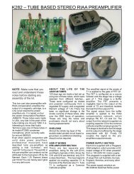
<strong>Users</strong> <strong>Guide</strong> <strong>for</strong> <strong>the</strong> <strong>Non</strong>-<strong>Inverted</strong> <strong>LM3875</strong> <strong>Kit</strong> Written by Brian Bell and Sandy H. 20 (26)6. Here is a picture of my chassis with <strong>the</strong> boards mounted:And a close-up of <strong>the</strong> amplifier PCB:Assuming that you took care of tying <strong>the</strong> input and output to <strong>the</strong> board, it shouldnow be a functional amplifier.
<strong>Users</strong> <strong>Guide</strong> <strong>for</strong> <strong>the</strong> <strong>Non</strong>-<strong>Inverted</strong> <strong>LM3875</strong> <strong>Kit</strong> Written by Brian Bell and Sandy H. 21 (26)3.3 Chassis ConsiderationsThere are many options on chassis design. Much of this us up to <strong>the</strong> builder’s taste,tools, budget and time. One fundamental issue which is <strong>the</strong> same, regardless of finaldesign, is safety. The chassis keeps dangerous voltages from harming anyone oranything that is in <strong>the</strong> area of <strong>the</strong> amplifier.The chassis must be properly grounded to <strong>the</strong> mains ground to prevent possibly lethalvoltages from being seen on <strong>the</strong> chassis in <strong>the</strong> event of failure. Ground loops, whichcommonly are a source of hum in situations may still be alleviated by proper chassislayout, shielding and <strong>the</strong> use of a star ground. Stopping <strong>the</strong> source of hum is <strong>the</strong> onlyoption, instead of disconnecting <strong>the</strong> chassis ground. At times, when connected to acomplex system, hum can be caused by interfacing to coax cable used <strong>for</strong> video. Trydisconnecting this cable from <strong>the</strong> system entirely and if this solves <strong>the</strong> problem,consider an isolation trans<strong>for</strong>mer <strong>for</strong> cable systems. Chassis layout also can affecthum. Keeping signal level wiring away from <strong>the</strong> trans<strong>for</strong>mer is a good place to start.Just about anything which can safely isolate <strong>the</strong> user from <strong>the</strong> amplifier could be aviable chassis. Some great and creative examples can be found on www.briangt.comas well as o<strong>the</strong>r sites on <strong>the</strong> Internet. Some designs focus on aes<strong>the</strong>tics, while o<strong>the</strong>rsoffer simplicity and o<strong>the</strong>rs focus on optimising various materials to provide a stableplat<strong>for</strong>m <strong>for</strong> <strong>the</strong> amp to subjectively sound its best.The last consideration <strong>for</strong> chassis construction is heatsinking. This amplifier does notrequire huge heatsinks. Successful implementations have used computer heatsinkswithout fans, solid pieces of bar stock or aluminum angle and o<strong>the</strong>rs rely on standardlarge heatsinks. An aluminum plate around 3” x 3” x ½” should be plenty <strong>for</strong> mostapplications if allowed to circulate in free air.When attaching a torrodal trans<strong>for</strong>mer to <strong>the</strong> chassis, care must be taken to not createa shorted turn. This occurs when a ferrous (metal) object creates a loop through <strong>the</strong>center of <strong>the</strong> trans<strong>for</strong>mer. In <strong>the</strong> following example, eliminating <strong>the</strong> top metal bracketand using only <strong>the</strong> washer supplied with <strong>the</strong> trans<strong>for</strong>mer would eliminate <strong>the</strong> shortedturn.
<strong>Users</strong> <strong>Guide</strong> <strong>for</strong> <strong>the</strong> <strong>Non</strong>-<strong>Inverted</strong> <strong>LM3875</strong> <strong>Kit</strong> Written by Brian Bell and Sandy H. 22 (26)3.4 Volume ControlVolume control can be achieved by use of a receiver or pre-amp or via signalattenuation. An attenuator can be made using a potentiometer with a shunt resistor ora multi-position switch with various combinations of resistors to attenuate <strong>the</strong> signal toappropriate levels. If a switch is used, a make be<strong>for</strong>e break switch should be used to toeliminate <strong>the</strong> possibility of popping when switching from one setting to ano<strong>the</strong>r.If a receiver or pre-amp is used and has sufficient gain, <strong>the</strong> amplifier could beoverpowered and clipping could occur. If <strong>the</strong> volume control on <strong>the</strong> pre-amp getsextremely loud with small variation, lowering <strong>the</strong> gain of <strong>the</strong> amplifier is in order. Lower<strong>the</strong> gain of <strong>the</strong> amplifier by varying R3 per <strong>the</strong> equation Gain = 1+ Rf/R3. The standardsupplied gain set by R3 is 33dB. Gain should remain above 10dB to reduce <strong>the</strong> chanceof <strong>the</strong> amplifier going into oscillation. To lower <strong>the</strong> gain, increase <strong>the</strong> value of R3.The following diagram shows <strong>the</strong> wiring scheme <strong>for</strong> a typical three-leg potentiometer:Here is an example of a Noble stereo potentiometer:
<strong>Users</strong> <strong>Guide</strong> <strong>for</strong> <strong>the</strong> <strong>Non</strong>-<strong>Inverted</strong> <strong>LM3875</strong> <strong>Kit</strong> Written by Brian Bell and Sandy H. 23 (26)4 Miscellaneous In<strong>for</strong>mation4.1 The Zobel NetworkA brief description of <strong>the</strong> implementation of a Zobel network and why this would bedone follows. Please note that this is per <strong>the</strong> recommendation of some experienceddesigners and is included in <strong>the</strong> National datasheet. As of this time, I have not tried <strong>the</strong>implementation of a Zobel with this amp and have suffered no apparent ill effects. Ihave included this option, as it may prove useful to some users.What does <strong>the</strong> Zobel do? It helps prevent high frequency oscillation, which may occurwith difficult loads/capacitive cables. Basically, it creates a low pass filter, with <strong>the</strong>2.7uF cap and 1 ohm resistor creating a pole at 1/(2*pi*r*c), which can solve issueswith cables, as well as reducing RF interference. According to some people, <strong>the</strong>Zobel can have a negative effect on <strong>the</strong> sonic per<strong>for</strong>mance. I haven't triedit myself to see. Builders who are concerned about <strong>the</strong> presence of oscillationsinduced by cables should indeed experiment with this addition and are encouraged topost <strong>the</strong>ir results!4.2 The Bridged <strong>LM3875</strong>The following is a brief explanation of options <strong>for</strong> bridging <strong>the</strong> <strong>LM3875</strong> chip. There aremany different options, including buffering, which would result in a different topologythan <strong>the</strong> one alluded to below.The first thing you need to determine is <strong>the</strong> load you want to drive. Keepin mind <strong>the</strong> effect of bridging and paralleling of amplifiers:- When you bridge an amplifier, this means that you will invert <strong>the</strong> signalphase and send it into one channel, while sending <strong>the</strong> normal phase into <strong>the</strong>o<strong>the</strong>r channel. This effectively creates an input signal of twice <strong>the</strong>amplitude. With <strong>the</strong> two channels bridged, each channel sees 1/2 <strong>the</strong> loadimpedance, meaning that if <strong>the</strong> speaker was 8 ohms, each amp would see 4ohms. Since this is true, you need to make sure that you are not drivingtoo low of a load with a bridged set-up. Note that <strong>the</strong> normal phase amp isdriving <strong>the</strong> + input <strong>for</strong> <strong>the</strong> speaker, while <strong>the</strong> inverted amp is driving <strong>the</strong> -input to <strong>the</strong> speaker.- When you parallel 2 channels, you are sending <strong>the</strong> same signal into bothchannels, causing each amplifier to see twice <strong>the</strong> load, meaning that a 4 ohmspeaker would cause each amp to see an 8-ohm load. Note that <strong>the</strong> outputs of<strong>the</strong> paralleled amplifier are tied toge<strong>the</strong>r, and each should be in serieswith a 0.22ohm resistor.Now, to figure out <strong>the</strong> power, simply figure out how much load each amplifieris driving. If you are driving 8-ohm speakers and bridging, <strong>the</strong> power willmore than double. If you are driving a 4-ohm speaker with a paralleledset-up, <strong>the</strong> power will increase, but not quite double.
<strong>Users</strong> <strong>Guide</strong> <strong>for</strong> <strong>the</strong> <strong>Non</strong>-<strong>Inverted</strong> <strong>LM3875</strong> <strong>Kit</strong> Written by Brian Bell and Sandy H. 24 (26)The ultimate configuration <strong>for</strong> power would be a bridged-parallelconfiguration with 4 amplifiers per channel.Paralleling is easy, with <strong>the</strong> addition of <strong>the</strong> 0.22 ohm resistors in serieswith <strong>the</strong> output. Bridging will require a circuit that will invert <strong>the</strong> phaseof one channel, such as a simple circuit using <strong>the</strong> DRV134.Feel free to search <strong>for</strong> more on your favourite website <strong>for</strong> more background on bridgingthis amp or look into <strong>the</strong> LM4870 chip discussions.4.3 An Input BufferNick Whetstone at Decibel Dungeon has compiled some in<strong>for</strong>mation from o<strong>the</strong>rsources regarding <strong>the</strong> addition of an input buffer. It is a good place to start todetermine if this addition is something you would like to try. The following diagram isposted with Nick’s permission and is one way to achieve a simple buffer <strong>for</strong> <strong>the</strong> circuit.If this addition interests you, be sure to check out Nick’s websitehttp://www.decdun.fsnet.co.uk , as well as those of his references and <strong>the</strong> typical <strong>DIY</strong>sites <strong>for</strong> additional in<strong>for</strong>mation.
<strong>Users</strong> <strong>Guide</strong> <strong>for</strong> <strong>the</strong> <strong>Non</strong>-<strong>Inverted</strong> <strong>LM3875</strong> <strong>Kit</strong> Written by Brian Bell and Sandy H. 25 (26)5 Frequently Asked Questions (FAQ)Here is a list that I compiled of frequently asked questions:5.1 What started this group order?I was teaching my friend how to use some PCB layout software <strong>for</strong> his projects, and Igave him <strong>the</strong> assignment to make a PCB <strong>for</strong> <strong>the</strong> gainclone, as it is <strong>the</strong> simplest circuitthat I know of, yet still functional. I had been playing around with <strong>the</strong> gainclone <strong>for</strong> <strong>the</strong>last year, trying different versions, but never actually taking it seriously. The circuit wasbased off of Peter Daniel’s simplified version that he posted on <strong>the</strong> <strong>for</strong>um. My friendreturned to me a board layout that was twice <strong>the</strong> size of <strong>the</strong> current board, and had longunholy traces running everywhere. I decided that I would make my own layout andshow him what I thought would be <strong>the</strong> best implementation. I spent a night working onit, and posted <strong>the</strong> result <strong>the</strong> next day to <strong>DIY</strong>audio to see if o<strong>the</strong>rs had comments on it. Ireceived several e-mails requesting boards, and a recommendation to offer a kit, as Ihad chosen a specific set of components <strong>for</strong> <strong>the</strong> design.Anyway, I worked on <strong>the</strong> design more, and started a new thread a couple of days laterto see how much interest a group order of pcbs <strong>for</strong> this would generate. There wasquite a substantial interest, so I created a rectifier PCB also, and decided to put 2channels + rectifier on a single PCB. I worked with Peter Daniel to refine my PCBlayout, and get a design that would be work best, <strong>for</strong> chassis mounting, and optimalsignal paths. I researched components and availability and put up an order page.From here, I generated orders <strong>for</strong> well over 100 kits.5.2 Where did you first find out about <strong>the</strong> gainclone?There was a discussion on <strong>DIY</strong>audio over a year ago about <strong>the</strong> term Frugal-phile,which Dave (planet10) started by saying:“It is relatively easy to spend big-bucks and get a reasonable sounding hifi (but not aseasy as you might think, given <strong>the</strong> number of mega-buck audio-pile systems that arenot very listenable). The goal here is to spend as little as possible and get a hifi that ismusically enjoyable.”From this, I got curious about what kind of amplifiers would be considered Frugalphile.I asked about it, and <strong>the</strong> term GainKlone came up. I found a reference to <strong>the</strong>Chip Amp Forum. From here, I saw Thorsten’s design, and decided to try it. I madeone, and never took it seriously, until I saw Peter Daniel’s latest amplifiers. At thispoint, I was hooked on using <strong>the</strong> gainclone.
<strong>Users</strong> <strong>Guide</strong> <strong>for</strong> <strong>the</strong> <strong>Non</strong>-<strong>Inverted</strong> <strong>LM3875</strong> <strong>Kit</strong> Written by Brian Bell and Sandy H. 26 (26)5.3 I just ordered <strong>the</strong> PCB set, what premium components should I use with it?If you want to use premium components, like I used with <strong>the</strong> kits, here are a list ofvendors that carry <strong>the</strong>se parts:Riken resistors: Michael Percy: www.percyaudio.com, Angela: www.angela.comCaddock resistors: Michael Percy: www.percyaudio.com,pcX: www.partsconnexion.comBlackgate caps: Michael Percy: www.percyaudio.com,pcX: www.partsconnexion.com,Reference <strong>Audio</strong> Mods: www.referenceaudiomods.comRest of components: Digikey: www.digikey.comThe parts list <strong>for</strong> <strong>the</strong> boards is listed above in section 2.1.5.4 I would ra<strong>the</strong>r start with basic components, what works with <strong>the</strong> board?If you just want to use standard components, <strong>the</strong> board will work fine, and you canalways upgrade later on. Here is a parts list <strong>for</strong> Digikey:# Part Name/Description Digikey Part Number2 <strong>LM3875</strong>TF <strong>LM3875</strong>TF-ND4 1500uF 50v Panasonic FC Capacitor P10334-ND4 22.1k ohm resistor (min quantity = 5) PPC22.1KXCT-ND2 680 ohm resistor (min quantity = 10) P680BBCT-ND2 220 ohm resistor (min quantity = 5) PPC20.0KXCT-ND8 On Semiconductor MUR860 fast diodes MUR860OS-ND2 4.7uF 50v Panasonic FC Capacitor P10315-NDIf you are just buying <strong>the</strong>se components <strong>for</strong> yourself from Digikey, in small quantities,expect to pay about $35 <strong>for</strong> all <strong>the</strong>se parts, plus shipping from Digikey. The budget kitwill cost around $35, including all of <strong>the</strong> parts above and a PCB set.5.5 I have a suggestion <strong>for</strong> material to be added to this manualFeel free to drop an e-mail to: manual@chipamp.com and I will try to look over thisaccount once and a while to make revisions to this manual.Thanks to Sandy <strong>for</strong> all of his help in preparing this manual.