Gather Harvest Installation Instructions (3.30MB PDF) - Allsteel
Gather Harvest Installation Instructions (3.30MB PDF) - Allsteel
Gather Harvest Installation Instructions (3.30MB PDF) - Allsteel

Create successful ePaper yourself
Turn your PDF publications into a flip-book with our unique Google optimized e-Paper software.
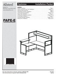
<strong>Gather</strong>Illustration 1. Access Door RemovalIllustration 2. Beam AttachmentBeamAttachmentBracketEnd PanelAssembly<strong>Harvest</strong> <strong>Installation</strong>SheetmetalScrewSlidingDoorSlotsDoorFastenerFor beam bracket attachment, the panel accessdoor will need to be removed and stored untiltable assembly is complete.Illustration 3. Beam/End Panel AssemblyThe beam attachment bracket will straddle the doorfastener. Attach the beam bracket using the bottom 6holes to the metal vertical of the end panel. Note that theslots for the sliding doors are oriented toward the centerof the end panel.There are a total of 4 mounting locations (total of 24sheetmetal screws) used in this step of the installation.343-3047Page 1 of 8 (07/12)
<strong>Gather</strong><strong>Harvest</strong> <strong>Installation</strong>Illustration 7. Bezel Cap <strong>Installation</strong>Bezel CapSheetmetalScrewElectricalClampBracketIf the end condition electrical is not being used,a cover can be installed to cover up the clearancecutouts in the bezel. Slide the bezel cap on topof the base to the bezel until the inside of thebezel cap comes into contact with the electricalclamp bracket.With the bezel cap fully seated against theelectrical clamp bracket, install the 2 sheetmetalscrews to secure it. There is 1 bezel cap suppliedper powered end panel.Illustration 8. Worksurface AttachmentMachine ScrewThe interior screw location on thefull top is a particle board screw.Note: Method described in Illustrations 8 & 9is for the split top model. Pilot holes forthe full top model match the same holeconfiguration as the split top unit.Single sided tops of a split top unit have7 pilot holes.1 set of 2 pilot holes lines up withthe outside set of holes in the end paneltop bracket (Illustration 8 & 9).There is a final set of 3 pilot holes that lineup with the holes in the beam assembly(Illustration 9).Install all 14 screws (7 per side) for bothsides loosely before checkingfor surface edge and end panel facealignment (Illustration 10).Trough – Cavity createdbetween 2 assembledbeam assemblies343-3047Page 3 of 8 (07/12)
<strong>Gather</strong><strong>Harvest</strong> <strong>Installation</strong>Illustration 9. Pilot Hole & Insert LocationsPilotInserts forsplit topInserts forfull topPilot for fulltop1 pilot hole and 2 inserts are located in this configurationon each corner of the table. Total of 4 pilot holesand 8 inserts. The full top has a total of 8 pilot holesand 4 inserts.2 pilot holes are located in the center of the table(total of 2).343-3047Page 4 of 8 (07/12)