EM-241A DC-MOTOR CONTROLLER 12-24V 15A - Electromen
EM-241A DC-MOTOR CONTROLLER 12-24V 15A - Electromen
EM-241A DC-MOTOR CONTROLLER 12-24V 15A - Electromen
- No tags were found...

You also want an ePaper? Increase the reach of your titles
YUMPU automatically turns print PDFs into web optimized ePapers that Google loves.
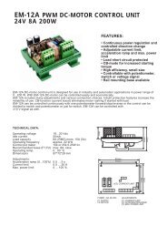
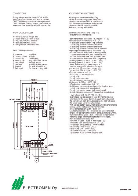
CONNECTIONSSupply voltage must be filtered <strong>DC</strong> of 10-35V,and ripple should be less than 30% at full load.CAUTION ! Wrong polarity can damage the unit.CAUTION ! Unit doesn't have an internal fuse, soan external fuse should be added if fuse required.MONITORABLE VALUES1/5 Motor current 0-20A ( 0-200)2/5 PWM-level-% 0-100% (0-100)3/5 hour counter (max.65535h)4/5 start counter (max.65535)5/5 carry counter for start counterFAULT-LED signal codes1. power on one blink2. current on limit led is lit3. current trip fast blinking...4. zero-cur trip long blink- short pause...5. overvoltage 4 x blink -pause...6. overheat short blink- long pause...7. timeout 3 x blink + long blink...8. fault input 2 x short + 1x long blink...ADJUSTMENT AND SETTINGSAdjusting and parameter setting of eg.current limit value, ramp times and speed-2value is done with the <strong>EM</strong>-236 interface unit.With <strong>EM</strong>-236 the parameters and adjustedvalues can also be copied to multibledevices accurately and reliably.SETTABLE PARAMETERS prog v1.3( defaults values in brackets )1 command mode: continuous = 0, impulse= 1 ( 0 )2 start condition combinations: 0-3 ( 1 )0= start both direction after I-trip and Stop1= start only opposite direction after I-trip2= start only opposite direction after Stop3= start only opposite direction after I- and Stop3 input logic combinations 0-3 PNP/NPN ( 0 )0= command and limit inputs as PNP ( positive )1= command inputs NPN, and limit inputs PNP2= command inputs PNP. and limit input NPN3= command and limit inputs NPN ( negative )4 running speed-1: 0-100% / 0-100 ( 100 )5 running speed-2: 0-100% / 0-100 ( 50 )Note: If selected to 0 "speed2-input" isused as analog 0-5V speed control input.6 current limit FW: 0.1-20A / 1-200 ( 30 )7 current limit REV: 0.1-20A / 1-200 ( 30 )8 Trip combinations: 0-3 ( 1 )0= no I-trip, no zero-current-trip1= only I-trip2= only zero-current-trip3= both I-trip and zero-current-trip9 I-trip delay: 0-255ms / 0-255 ( 20 )10 Fault output combinations: 0-3 ( 1 )0= I-trip and zero current won´t cause fault output signal1= only I-trip causes fault output signal2= only zero current causes fault output signal3= both I-trip and zero currenT causes fault output signal.11 overvoltage limit: 15-40V / 15-40 ( 35 )Overvoltage can be caused by load driving the motor orwhen braking the speed down but supply can not acceptthe current back from driver. Exceeding the limit will causethe power stage set to free-wheel state.With a direct battery supply the brake current is charging thebattery and the voltage will not normally rice.<strong>12</strong> load compensation: 0-255 / 0-255 ( 0 )Load compensation ( RxI ) improves low speed and starttorgue, but too high compensation achieve unstable running.Run motor at low speed ( 30% ) Increace compensationwith small steps until motor start behaviour unstable,then decrease value about 10%13 timeout: 0-255s. / 0-255 (0=not in use) ( 0 )14 Reset for start and hour-counter 0/1 ( 0 )selecting 1 and push save = reset counters15 start ramp: 0-5s / 0-500 ( 100 )16 stop ramp: 0-5s / 0-500 ( 100 )17 start kick 0-200ms / 0-200 ( 0 )gives short 0-200 full drive pulse for startELECTROMEN Oywww.electromen.com