Calculation Sheets
Calculation Sheets Calculation Sheets
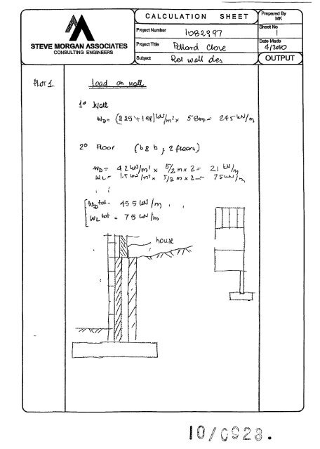
S^ STEVE MORGAN ASSOCIATES CONSULTING ENGINEERS ftdvl. I t "V v^ CALCULATION SHEET "v; Project Number loe^S97 '"^^'='^ PdUxvro\ Oove Subject Q^ ^JX CU^ - ^ nzcr /^ 0 O f5) W ^ £ O Prepared By MK Sheet No Date Made 4l1&\0 ^ OUTPUT ^ - ^
- Page 2: 300^ STEVE MORGAN ASSOCIATES CONSUL
- Page 5 and 6: ^ STEVE MORGAN ASSOCIATES CONSULTIN
- Page 7 and 8: CSC•T€DDS Steva Moi^n Associate
- Page 9 and 10: CSC•TGDDS Steve Morgan Assodates
- Page 11 and 12: CSC•TEDDS Steve Morgan Associates
- Page 13 and 14: CSC • TGDD5 Steve Morgan Associat
- Page 15 and 16: CSC > TEDDS Stevs Morgan Associates
- Page 17 and 18: CSC•TEDDS Steve Morgan Associates
- Page 19 and 20: CSC • TEDDS Steve Morgan Associat
- Page 21 and 22: CSC • TEDDS- Steve Morgan Associa
- Page 23 and 24: CSC•TEDDS Steve Morgan Assodales
- Page 25 and 26: CSC >TEDDS Steve Morgan Associates
- Page 27 and 28: CSC • TEDDS Stave Morgan Associat
- Page 29 and 30: CSC•TEDDS Steve Moi^n Associates
S^<br />
STEVE MORGAN ASSOCIATES<br />
CONSULTING ENGINEERS<br />
ftdvl.<br />
I t<br />
"V<br />
v^<br />
CALCULATION SHEET "v;<br />
Project Number<br />
loe^S97<br />
'"^^'='^ PdUxvro\ Oove<br />
Subject Q^ ^JX CU^<br />
- ^<br />
nzcr<br />
/^ 0 O f5)<br />
W ^ £ O<br />
Prepared By<br />
MK<br />
Sheet No<br />
Date Made<br />
4l1&\0<br />
^ OUTPUT ^<br />
- ^
300^<br />
STEVE MORGAN ASSOCIATES<br />
CONSULTING ENGINEERS<br />
)r<br />
2A00<br />
"V<br />
CALCULATION SHEET "V^<br />
Project Number<br />
Project Tttle<br />
lotz?^i<br />
\o\K^A CllD'^<br />
Subject Kef W(2^ des<br />
\G0 2^0 \.oo<br />
\ '''\^^ t"^^^^ ^oU.<br />
4-<br />
45D<br />
-t~<br />
^VO<br />
^<br />
35+5^ 4?<br />
40 it^ch^ 75 'f^/m' 4-*- \<br />
I'tYl<br />
OU'f N<br />
/<br />
4SO<br />
-^ - - - — - ^<br />
/<br />
Prepared By<br />
MK<br />
J<br />
Sheet No<br />
1<br />
Date Made<br />
4{lOVO<br />
^ OUTPUT ]<br />
-A.<br />
V^rr\<br />
^cr^<br />
m<br />
c20J
^f^-O<br />
'StO<br />
STEVE MORGAN ASSOCIATES<br />
CONSULTING ENGINEERS<br />
7-<br />
7-<br />
> ^<br />
miL (^<br />
V>,^4\tr^ ^<br />
[ho a<br />
/<br />
"V<br />
^<br />
CALCULATION SHEET "YP<br />
Project Number<br />
(ti'^a^fl<br />
ProjectTrtle p^^^^{ ^ ^<br />
-A.<br />
Subject 1 ^ Wv^ d^J<br />
-^tt?<br />
K_<br />
I<br />
/<br />
/<br />
(h7er<br />
i^?8r<br />
'repared By<br />
MK<br />
Sheet No<br />
f<br />
Date Made<br />
--6s. OUTPUT >
^<br />
STEVE MORGAN ASSOCIATES<br />
CONSULTING ENGINEERS<br />
a^c^<br />
v^<br />
^<br />
CALCULATION SHEET "V?<br />
Project Number 1.^ '^/'*?
c{ Vu^<br />
Subject R^^ 1/1/^ (pU)<br />
lioci<br />
: ^<br />
PUjftV^<br />
\?o<br />
/<br />
4TO<br />
|(^pC> UPI ^-S^<br />
—^Kr^r<br />
C f c ^<br />
axioo<br />
^^O^lPOciQ<br />
!mo<br />
\ /-^<br />
ASo VsO<br />
c<br />
4rc)<br />
?)5«:^<br />
K^ ^5 SO-.,<br />
:—UQ hi^UK-<br />
Sheet No<br />
z<br />
Date Made<br />
^ OUTPUT ]<br />
-A.<br />
inn^<br />
im<br />
f^ia^f K:?^ IJ-
CSC•T€DDS<br />
Steva Moi^n Associates<br />
Consulting Engineers<br />
Project<br />
Section<br />
Gate, by<br />
M<br />
RETAINING WALL ANALYSIS (BS 8002 1994)<br />
Wall details<br />
Retaining wall type<br />
Height of retaining wall stem<br />
Thickness of wall stem<br />
Length of toe<br />
Length of heel<br />
Overall length of base<br />
Thickness of l)ase<br />
Depth of downstand<br />
Positon of downstand<br />
Thickness of downstand<br />
Height of retaining wall<br />
Depth of cover in front of wall<br />
•^5^"<br />
Depth of unplanned excavation<br />
Height of ground water behind wall<br />
Height of saturated fill above base<br />
Density of vi/all construction<br />
Density of base construction<br />
Angle of rear face of wall<br />
/\ngle of soil surtece behind wall<br />
k-<br />
Effective height at virtual back of wall<br />
Retained matenal details<br />
Mobilt^bon factor<br />
»»* KfeBa%.<br />
Pollard Close<br />
/Plqt;;lftRW hstem=3000mm^<br />
Date<br />
22/04/2010<br />
-2450-<br />
-2400-<br />
-3200-<br />
Chkdby<br />
—>|«45eH350|^<br />
53kN/m<br />
II<br />
1%<br />
Unpropped cantitever<br />
hstem == 3000 mm<br />
trail = 450 mm<br />
Itoa = 2400 mm<br />
Iheai = 350 mm<br />
^ ^ ^<br />
Ibass = Itoe + Iheal + twoll = 3200 mm<br />
tbasa = 350 mm<br />
dds = 0 mm<br />
Ids = 1300 mm<br />
tds = 350 mm<br />
hwan = hstem + tbase + dds = 3350 mm<br />
dcover = 450 mm<br />
daxc = 450 mm<br />
hwater — 0 mm<br />
Job Ref<br />
Sheet no/rev<br />
1082997<br />
Date Appdby Date<br />
SkN/nf<br />
hsat = max(hwater tbase - dds 0 mm) = 0 mm<br />
•yvvai = 23 6 kN/m^<br />
Ybasa = 23 6 kN/m^<br />
a = 90 0 deg<br />
P = 0 0 deg<br />
heff = hvrai + Iheal X tanO) = 3350 mm<br />
M = 15<br />
TEDDS calculation version 1 2.01 00
CSC•TEDDS<br />
Steve Morgan Associates<br />
Consulting Engineers<br />
Project<br />
Section<br />
Gate, by<br />
M<br />
Pollard Close<br />
Ploti RW hslem=3000mm<br />
Date<br />
22/04^010<br />
Moist density of retained material > = 18 0 klM/m^<br />
Saturated density of retained matenal ^s = 21 0 klM/m^<br />
Design shear strength ^ = 24 2 deg<br />
Angle of wall fhcton 5 = 18 6 deg<br />
Base material details<br />
Moist density<br />
Design shear strength<br />
Design base fhction<br />
Allowable beanng pressure<br />
Using Coulomb ttieory<br />
Active pressure coefficient for retained matenal<br />
Ymb = 18 0 mirrP<br />
i|ib = 24.2 deg<br />
5b = 18 6 deg<br />
Pbaaibig = 75 kN/m^<br />
ChKdby Date<br />
Job Ref<br />
Sheet no Jrev<br />
1082997<br />
2<br />
Ai^dby Date<br />
Ka = sin(a + ^f/ (sin{a)2 x sin(a 5) x [1 + V{sln{(|> + 5) x sin(^ - P)/ (sin(a 5) x sin{a + P)))F) = 0 369<br />
Passive pressure coefficient for base material<br />
At rest pressure<br />
At rest pressure for retained material Ko = 1 - sin{(t>) = 0 590<br />
Loading details<br />
Surcharge load on plan<br />
Applied vertical dead load on wall<br />
Applied vertical live load on wall<br />
Position of applied vertcal load on wall<br />
Applied honzontal dead load on wall<br />
Applied honzontal live load on wall<br />
Height of applied honzontal load on wall<br />
.^ yA<br />
25 0<br />
Kp = sin(90 i|i bf I {sln{90 8b) x [1 - V(sin(it> b + &) x sin(i|> b) / (sin(90 + 8b)))F) = 4187<br />
Surcharge = 7^ kN/m^<br />
Wdaad = 45 0 kN/m<br />
Wov9 = 75kN/m<br />
Lad = 2450 mm<br />
Fdaad = 0_0 kN/m<br />
Fiivs = 0^ kN/m<br />
hioad = 0 mm<br />
"'fnnfflnnnu;'<br />
53<br />
P4 4<br />
2 6 21 1<br />
Loads shown In kN/m pressures shown In kN/m*
CSC•TGDDS<br />
Steve Morgan Assodates<br />
Consulting Engineers<br />
Vertical forces on wall<br />
Wall stem<br />
Wall base<br />
Surcharge<br />
Moist backfill to top of wall<br />
Soil in front of wall<br />
Applied vertical load<br />
Total verflcal load<br />
Horizontal forces on wall<br />
Surcharge<br />
Moist backfill above water teble<br />
Total horizontal load<br />
Project<br />
Section<br />
Calculate stability against sliding<br />
Cal&by<br />
M<br />
Passrve resistance of soil in front of wall<br />
Resistance to sliding<br />
Overturning moments<br />
Surcharge<br />
Moist backfill above water table<br />
Total overturning moment<br />
Restoring moments<br />
Wall stem<br />
Wall base '<br />
Moist backfill<br />
Design vertical dead load<br />
Total restonng moment<br />
Check stability against overturning<br />
Total overtuming moment<br />
Total restoring momeirt<br />
Check beanng pressure<br />
Surcharge<br />
Soil in front of wall<br />
Design vertical live load<br />
Total moment for bearing<br />
Total vertical reaction<br />
Distance to reaction<br />
Eccentricity of reaction<br />
Beanng pressure at toe<br />
Beanng pressure at heel<br />
I<br />
PoUard Close<br />
Ploti RWhstem=3000mm<br />
Date<br />
22/04/2010<br />
Chkdby Data<br />
Wiran = hstein X tvoD X Yviaa = 31 9 kN/m<br />
VWbasa = Ibasa X tbase X Ybase = 26 4 kN/m<br />
vfeur = Surcharge x iheai = 26 kN/m<br />
Win_w = Ihasl X (hstam hsal) x ym = 18 9 kN/m<br />
Wp = hooX dcover X ymb = 194 kN/m<br />
Wv = Wdaad + Wnva = 525 kN/m<br />
Job Ref<br />
Sheet no^rev<br />
1082997<br />
3<br />
Appdby Data<br />
Wtotal = Wvaa + Wbass + Wsur + Wnuw + Wp + Wv = 151 8 kN/m<br />
Fsur = Ka X cos(90 a + 5) x Surcharge x hag = 8 8 klM/m<br />
Fin.a = 0 5 X Ka X cos(90 - a + 5) X Ym X (hoH hwatei)? = 353 kN/m<br />
Ftolal = Fsur + Fni_a = 441 kN/m<br />
Fp = 0 5 X Kp X C0S(5b) X (deovar + tbasa + dds - dgasf x ymb = 4^ kN/m<br />
Fres = Fp + (Wtotal - Wsur - Wp - Wave) X tan(5b) = 455 kN/m<br />
PASS ' Resistance force te greater than sliding force<br />
Msur=Fsurx{h89 - 2 X dds) / 2 = 14.7 kNm/m<br />
Mm_a = Fm_a x (half + 2 x hvtatar - 3 x dds) / 3 =» 39J5 kNm/m<br />
Mot = Msur + Mm_a = 54.2 kNm/m<br />
MwaD = Wivaa X (hoa + twan / 2) = 836 kNm/m<br />
Mbasa = Wbasa X kasa / 2 = « 3 kNm/m<br />
Mni_r = (Whuw X (base - Iheal / 2) + Wtn_3 x (base Iheal / 3)) = 57 2 kNm/m<br />
Mdead = Wdead x Wd ^110 3 kNm/m<br />
Mresl = MwaO + Mbase + MITLT + Mdaad = 293.3 kNm/m<br />
Mot = 54.2 kNm/m<br />
Mfest = 293 3kNm/m<br />
PASS Restoring moment is greater than overtuming moment<br />
Msur_r = Vfeur X (base Iheel / 2) = 7 9 kNm/m<br />
Mpj-= wk) X Itoe / 2 = 233 kNm/m<br />
Move = Wiive X lioad = 18 4 kNm/m<br />
Mtoiai = Mrest Mot + Msur_r + Mp_r + Mnva = 288.8 kNnr/m<br />
R = W,otai = 1518 kN/m<br />
Xbar = Mtotal / R = 1903 mm<br />
e = abs({lbase/2) Xbar) = 303 mm<br />
Ptoe = (R/lbas9) (6xRxe/lbas8^) = 205kN/m2<br />
Phsel = (R/ Ibasa) + (6 X R X e / Ibase^ = 744 kN/m^<br />
Reaction acts withm middle third of base<br />
PASS Maximum bearing pressure Is less than allowable beanng pressure
CSC • TEDD5<br />
Steve Morgan Associates<br />
Consulting Hn^eers<br />
Project<br />
Section<br />
Cal&by<br />
M<br />
RETAINING WALL DESIGN (BS 8002 1994)<br />
Ultimate limit state load Actors<br />
Dead load factor<br />
Live load liactor<br />
Earth and water pressure factor<br />
Factored vertical forces on wail<br />
Wall stem<br />
Wall base<br />
Surcharge<br />
Moist backfill to top of wall<br />
Soil in front of wall<br />
Applied vertical load<br />
Total vertical load<br />
Factored horizontal at-rest forces on wall<br />
Surcharge<br />
Moist backfill above water table<br />
Total horizontal load<br />
Passive resistance of soil in front of wall<br />
kN/m<br />
Factored overtuming moments<br />
Surcharge<br />
Moist backfill above water table<br />
Total overtuming moment<br />
Restoring moments<br />
Waflstem<br />
Wall base<br />
Surcharge<br />
Moist backfill<br />
Soil in front of wall<br />
Design vertical load<br />
Total restonng momerrt<br />
Check stability against overturning<br />
Total overtuming moment<br />
Total restonng moment<br />
Factored bearing pressure<br />
Total moment for beanng<br />
Total vertical reaction<br />
Distance to reaction<br />
Eccentncity of reaction<br />
Beanng pressure at toe<br />
Beanng pressure at heel<br />
Pollard Close<br />
Ploll RW hstem=3000mm<br />
Date<br />
22/04/2010<br />
yiji = 1.4<br />
YLi = 1 6<br />
VLe = 1.4<br />
Chkdby Date<br />
WwalJ = YL«I X hstam X twan x ywaD = 44 6 klM/m<br />
WbaseJ = yi.
CSC•TEDDS<br />
Steve Morgan Associates<br />
Consulting Englneeis<br />
Rate of change of base reaction<br />
Beanng pressure at stem / toe<br />
Beanng pressure at mid stem<br />
Beanng pressure at stem / heel<br />
Project<br />
Sectton<br />
Caicby<br />
M<br />
Pollard Close<br />
Plotl RW hstem=3000mm<br />
Date<br />
22A)4/2010<br />
Design of reinforced concrete retaining wall toe (BS 8002 1994)<br />
Material properties<br />
Charactenstic strength of concrete<br />
Charactenstic strengUi of reinforcement<br />
Base details<br />
Minimum area of reinforcement<br />
Cover to reinforcement in toe<br />
Calculate shear for toe design<br />
Shear from beanng pressure<br />
Shear from weight of base<br />
Total shear for toe design<br />
Calculate moment for toe design<br />
Moment from beanng pressure<br />
Moment from weight of liase<br />
Total moment for toe design<br />
k<br />
Check toe in bending<br />
Widtii of toe<br />
Depth of reinforcement<br />
Constant<br />
Lever arm<br />
o<br />
Area of tension reinforcement required<br />
Minimum area of tension reinforcement<br />
Area of tension reinforcement required<br />
Reinforcement provided<br />
Area of reinforcement provided<br />
200-<br />
Chkdby Date<br />
rate = (Ptoe_f Pheel f) / Ibase = -3 43 kN/m'/m<br />
JobRsf<br />
Sheet no7rev<br />
1082997<br />
5<br />
AppVJby Date<br />
Pstsm_toe_f = max(pheai.f + (rateX (ihaai + t«ran)) 0kN/m*) = 698klM/m*<br />
Pstem_mid_t = max(pheei_f + (rate X (beai + twaB / 2)) 0 klM/m*) = 70 5 kN/m*<br />
Pstem_haei_f = max(phae(.t + (rate x Iheel) 0 kN/m*) = 71 3 kN/m*<br />
feu = 35 N/mm*<br />
fy = 500N/mm*<br />
k = 013%<br />
CtoB = 30 mm<br />
Vtoe_bear = (ptoej + PstBra_toa_f) x Itoa / 2 = 157 6 kN/m<br />
Vtoe_wt_base = yf_d X ybase x Itoe X tbase = 27 8 kN/m<br />
Vtoe = Vtoejjear Vine_wt.basa = 129 8 kN/m<br />
Mtoejjear = (2 x ptoej + Pstam_mld_f) X (hoe + t««aD / 2)^ / 6 = 222 4 kNm/m<br />
MiDe_vA.i>asB = (y»_d x ybasa x tbase x (W + twai / 2)^ / 2) = 39 8 kNm/m<br />
Mtoe = Mtoe_b8ar - MtoB_vit.base = 18Z5 kNm/m<br />
b = 1000mm/m<br />
dtoe = tbase - Ctoe - (l|>toe/ 2) = 310 0 mm<br />
Ktoe = Mtoe / (b X dtoe* x feu) = 0 054<br />
Compression reinforcement Is not required<br />
ztoe = min(0 5 + V(0 25 (min(Kto6 0 225) / 0 9)) 0 95) x dioe<br />
zioa = 290 mm<br />
As_toa_da3 = Mtoa / (0 87 X fy X Ztoe) = 1447 mm*/m<br />
As_toe_min = k X b X tbase = 455 mm*/m<br />
As_toB_req = Max(As_toe_das As_toe_min) = 1447 mm*/m<br />
20 mm dia bars @ 200 mm centres<br />
As_toe_prov = 1571 mm*/m<br />
PASS - Reinforcement provided at the retelning wall toe Is adequate
CSC • TEDDS<br />
Steve Morgan Associates<br />
Consulting Engirteers<br />
Check shear resistance at toe<br />
Design shear stress<br />
Allowable shear stress<br />
Project<br />
Sectton<br />
Calaljy<br />
M<br />
From BS8110 Part 1 1997-Table 3 8<br />
Design concrete shear stress<br />
Pollard Close<br />
Ploti RWhstBm=3000mm<br />
Data<br />
22A)4/2010<br />
Design of reinforced concrete retaining wall heel (BS 8002 1994)<br />
Material properties<br />
Charactensbc strengtii of concrete<br />
Charactenstic strength of reinforcement<br />
Base detcdls<br />
Minimum area of reinforcement<br />
Cover to reinforcement m heel<br />
Calculate shear for heel design<br />
Shear from beanng pressure<br />
Shear firom weight of base<br />
Shear from weight of moist backfill<br />
Shear from surcharge<br />
Total shear for heel design<br />
Calculate moment for heel design<br />
Moment from bearing pressure<br />
Moment from weight of base<br />
Moment from weight of moist backfill<br />
Moment from surcharge<br />
Total moment for heel design<br />
JL±.<br />
Check heel in bending<br />
Width of heel<br />
Depth of reinforcement<br />
Constarrt<br />
Lever arm<br />
1+100-H<br />
Chkdby Data<br />
vioe = Vtoe / (b X dtoa) = 0 419 N/mm*<br />
Job Ref<br />
Sheet noTrev<br />
1082997<br />
6<br />
App-d by Data<br />
vadm = min(0 8 x V(feu /1 N/mm*) 5) x 1 N/mm* = 4 733 N/mm*<br />
PASS - Design shear stress is less than maximum shear stress<br />
vojoe = 0 601 N/mm*<br />
feu = 35 N/mm*<br />
fy = 500 N/mm*<br />
k = 013%<br />
Cheei = 30 mm<br />
Vfoe < vc foe - Wo Shear reinforcement required<br />
Vhaeljjaar = ((>heeU + Pstamjieeu) X Ihaal / 2 = 25.2 kN/m<br />
Vheslj«l.base = yf_d x ybasa X Iheal X tbase = 4 kN/m<br />
Vheel_wt_m = WmjivJ = 26 5 kN/m<br />
Vheel_sur = WfeurJ = 4^ kN/m<br />
Vhaal = VheeLbeai' + VheeLwtJiasa + VheeUvUn. •*" Vheel_sur = 9_5 kN/m<br />
Mheel_baar = (2 x phaeU + PstBm_irtd_f) ^ (Ihsd + tifcail / 2)* / 6 = 119 kNm/m<br />
Mheel_v»t_base = (yf_d X ybase X tbase X (beei + twall / 2)* / 2) = ^9^ kNm/m<br />
MhBal_v«t_m = Wnjvf X (beel + twao) / 2 = JOS kNm/m<br />
Mheel_sur = WsurJ x (baal + twao) / 2 = 1_7 kNm/m<br />
Mhaal = Mheel_bear + MheeLwUtasa + Mheel_wUn + Mrieel_sur = ^^ kNm/m<br />
b = 1000 mm/m<br />
dhasi = tbase - Cheel — (ijlhEel/ 2) = 314 0 mm<br />
Kheel = Mheel / (b X dheel* X feu) = 0 001<br />
Compression reinforcement is not required<br />
Zheal = min(0 5 + V(0 26 (min(Kheal 0 225) / 0 9)) 0 95) X dhaal
CSC • TGDD5<br />
Steve Morgan Associates<br />
Consulting Engineers<br />
Project<br />
SecUon<br />
Calcby<br />
M<br />
/Vrea of tension reinforcement required<br />
Minimum area of tension reinforcement<br />
Area of tension reinforcement required<br />
Reinforcement provided<br />
Area of reinforcement provided<br />
Check shear resistance at heel<br />
Design shear stress<br />
Allowable shear stress<br />
FromBS8110 Part 1 1997-Table3,8<br />
Design concrete shear stress<br />
Pollani Close<br />
Ploti RWhstem=3000mm<br />
Date<br />
22/04/2010<br />
Zheei = 298 mm<br />
Chkdby Date<br />
As_heel_des = Mheal / (0 87 X fy X Zheal) = 18 mm*/m<br />
As_hael_mln = k X b X tbasa = 455 mm*/m<br />
Job Ref<br />
Sheet noJrev<br />
A3_hrat_req = Max(As_heel_das /^JiraUrtn) = 455 mm*/m<br />
B1131 mesh<br />
As_he^jMov = 1131 mm*/m<br />
1082997<br />
7<br />
Appdby Date<br />
PASS Reinforcement provided at tlie retaining vail heel Is adequate<br />
Vheel = Vheel / (b X dheel) = 0 030 N/mm*<br />
Vadm = min(0 8 x >/(feu /1 N/mm*) 5) x 1 N/mm* = 4.733 N/mm*<br />
PASS - Design shear stress Is /ess tftan maximum shear stress<br />
Vc heal = 0 534 N/mm*<br />
Design of cavity reinforced masonry retaining wall stem BS562&-2 2000<br />
Wall details<br />
Thickness of outer leaf of wall<br />
Thickness of inner leaf of wall<br />
Thickness of reinforced cavity<br />
Depth of stem reinforcement<br />
Masonry details<br />
Masonry type<br />
Compressive strengtti of units<br />
Mortar designation<br />
Category of manufactonng control of unite<br />
Partial safety factor for matenal strengtti<br />
-275-<br />
touter = 100mm<br />
timer = 100 mm<br />
tcavlly = twall touter tnnar = 250 mm<br />
dstem = 310 mm<br />
Aggregate concrete blocks no voids<br />
Puna = 10 0 N/mm*<br />
M<br />
Normal<br />
ynm = 2 3<br />
Characteristic compressive strength of masonry<br />
Least honzontal dimension of masonry units buna = 100 0 mm<br />
Height of masonry units<br />
huntt = 215 0mm<br />
Ratio of height to least horizontal dimension<br />
From BS5628 2 Table 3d mortar ii<br />
ratio = hunii / txjnit = 2.2<br />
Vheel < Vc_beei - No Shear reinforcement required
CSC•TEDDS<br />
Steve Morgan Associates<br />
Consufflng Engineers<br />
Project<br />
SecSon<br />
Characteristic compressive strength<br />
Calaby<br />
M<br />
Factored horizontal at rest forces on stem<br />
Surcharge<br />
Moist backfill above water table<br />
Calculate shear for stem design<br />
Shear at base of stem<br />
Calculate moment for stem design<br />
Surcharge<br />
Moist backfill above water table<br />
Total moment for stem design<br />
Check maximum design moment for wall stem<br />
Width of wall<br />
|y/la}dmum design moment<br />
Check wall stem in bending<br />
Moment of resistance factor<br />
Lever arm factor<br />
Lever annn<br />
Area of tension reinforcement required<br />
Minimum area of tension reinforcement<br />
Area of tensfon reinforcement required<br />
Reinforcement provided i<br />
Area of reinforcement provided<br />
Check shear resistance at wall stem<br />
Pollard Close<br />
Ploti RWhstem=3000mm<br />
Data<br />
22A)4/2010<br />
1k=ilN/mm*<br />
Chkdby Date<br />
Job Ref<br />
Sheet no^v<br />
1082997<br />
8<br />
AppMby Data<br />
Fs_surj = yuxKox Surcharge x (hen-tbaso dds) = 21 2 kN/m<br />
F3_m_a_f = 0 5 X yi_e X Ko X ym X (hair Ibase- dds - hsat)* = 66 9 kN/m<br />
Vstam = Fs_sur_f + Fs,m_^f = 882 kN/m<br />
Ms_sur = Fs_siirj x (hstem + tbase) / 2 = 35 6 kNm/m<br />
Wfc_m_a = Fs_in_a_tx (2x hsat + haff-dda + tbase/2)/3 = 786kNm/m<br />
Msiem = M3_sur + Ms_nua = 114J2 kNm/m<br />
b = 1000 mm/m<br />
Md_stero = 0 4 X lit X b X dstsm* / ymm = 1361 kNm/m<br />
PASS - Applied moment is less than maximum design moment<br />
Design shear stress Vstam = Vstam / (b x dstam) = 0 284 N/mm*<br />
Basic charactensbc shear sbrength of masonry fvbas = minIO 35 + (17 5 x As_stenu>rov / (b x dstam)) 0 7] x 1 N/mm*<br />
Shearspan<br />
Cfiaractenstic shear sb^ngtii of masonry<br />
Allowable shear stress<br />
Check limiting dimensions<br />
Limiting span/effecbve depth ratio<br />
Actual span/effocbve depth ratio<br />
Axial load check<br />
Factored a^dal load on wall<br />
Limiting axial load<br />
Q = Mstem / dstam* = 1J88 N/mm*<br />
Q = 2xcx(1 C)xfk/ymm<br />
0 = 0787<br />
zstem = min(0 95 c) x dstem = 243.8 mm<br />
As.stenudes = Mstem X yms / (^ x Zstertr) = 1077 mm*/m<br />
As_stam_min = k x b-x twai = 585 mm*/m<br />
As_stBm_req = Max(As_stBm_
CSC > TEDDS<br />
Stevs Morgan Associates<br />
Consulflng Engineers<br />
Prefect<br />
Sectfon<br />
Cal&by<br />
M<br />
Indicabve retaining wall reinforcement diagram<br />
Too relnforcement-<br />
Pollard Close<br />
Ploti RWhstem=3000mm<br />
Date<br />
22/04/2010<br />
Toe bars 20 mm dia @ 200 mm centres - (1571 mm*/m)<br />
Heel mesh - B1131 (1131 mm*/m)<br />
Stem bars 20 mm dia @ 275 mm centres C1142mm*/m)<br />
Chkdby Date<br />
=•, #<br />
•4-<br />
^ -<br />
Job Ref<br />
Sheet noTrev<br />
Stem rebiforcein eirt<br />
1082997<br />
9<br />
Appdby Data<br />
-Heel reinforcement
CSC >TEDDS<br />
Steve Morgan Associates<br />
ConsuWng Engineers<br />
Project<br />
Section<br />
Cate.by<br />
M<br />
RETAINING WALL ANALYSIS (BS 8002 1994)<br />
Wail details<br />
Retaining wall type<br />
Height of retaining wall stem<br />
Thickness of wall stem<br />
Length of toe<br />
Length of heel<br />
Overall lengtti of base<br />
Thickness of base<br />
Depth of downstand<br />
Position of downstand<br />
Thickness of downstand<br />
Height of retaining wall<br />
Depth of cover in front of wall<br />
Depth of unplanned excavation<br />
Height of ground water behind wall<br />
Height of satijrated fill above base<br />
Density of wall construction<br />
Density of base construction<br />
/Xngle of rear face of wall<br />
/\ngle of soil surface behind wall<br />
Effective height at virtual back of wall<br />
Retained material details<br />
Mobilisation factor<br />
Pollard Close<br />
Plori"'RWhs=300 0mm no point loaa<br />
Date<br />
22/04/2010<br />
H 1400 >|^460 >+*35'>H<br />
-2200-<br />
Chkdby Date<br />
Unpropped cantilever<br />
hstem = 3000 mm<br />
twag = 450 mm<br />
Itoe = 1400 mm<br />
Inaei = 350 mm<br />
base = Itoe + Iheel + turaU = 2200 mm<br />
tbasa = 350 mm<br />
dds = 0 mm<br />
Ids = 1350 mm<br />
tds = 350 mm<br />
hviaii = hstem + tbase + dds = 3350 mm<br />
dcovar = 450 mm<br />
daxc = 450 mm<br />
hv»ater = ^ mm<br />
hsat = max(hv«atBr tbase dds 0 mm) = 0 mm<br />
ywafl = 23 6 mjrrP<br />
ybasa = 23 6 kN/m^<br />
a = 90 0 deg<br />
P = 0 0 deg<br />
heff = hwaD + baei X tan(P) = 3350 mm<br />
M = 15<br />
Job Ref<br />
Sheet noTrev<br />
1082997<br />
10<br />
Appdby Date<br />
TEDDS calculation veiston 1J2.01 00
CSC•TEDDS<br />
Steve Morgan Associates<br />
Consulting Engineers<br />
Moist density of retained matenal<br />
Project<br />
Secflon<br />
Calcby<br />
M<br />
Saturated density of retained matenal<br />
Design shear strength<br />
Angle of wall miction<br />
Base matenal details<br />
Moist density<br />
Design shear strengtti<br />
Design base friction<br />
Allowable bearing pressure<br />
Using Coulomb theory<br />
Active pressure coefficient for retained matenal<br />
Pollard Close<br />
Ploti RWhs=3000mm no point load<br />
Data<br />
22/04/2010<br />
Chk-dby Date<br />
Job Ref<br />
Sheet no7rev<br />
1082997<br />
11<br />
Appdby Date<br />
Ka = sin(a + ^fl (sln(o)* x sin(a 5) x [1 + V(sin(i|) + 8) x sin( - p) / (sin(a 5) x sin(a + p)))]*) = 0 369<br />
Passive pressure coefficient for base matenal<br />
At rest pressure<br />
At rest pressure for retained matenal Ko = 1 - s\n[if) = 0 590<br />
Loading details<br />
Surcharge load on plan<br />
Applied vertical dead load on wall<br />
Applied vertical live load on wall<br />
Position of applied vertical load on wall<br />
Applied horizontal dead load on wall<br />
Applied honzontal live load on wall<br />
Height of applied honzontal load on wall<br />
ym = 180kN/m3<br />
ys = 210kN/m3<br />
(j) = 242 deg<br />
5 = 186 deg<br />
ymb = 18 0kN/m3<br />
^6 = 242 deg<br />
8b = 18 6 deg<br />
Pbearlng = 75kN/m*<br />
Kp = sin(90 if bf I (sin(90 6b) x [1 - >/(sin((^ b + 8b) x sln(ifr b) / (sin(90 + 8b)))F) = 4.187<br />
$«?RS;<br />
Surcharge = 75 kN/m*<br />
Wdead = 00 kN/m<br />
Wiive = OOW^'n<br />
lioad = 0 mm<br />
Fdead = 00 kN/m<br />
Fnve = 0 0 kN/m<br />
hioad = 0 mm<br />
!!^"4lKk- T<br />
k.^;!^<br />
IJJJIJJlllJJ^^<br />
^5555"<br />
2 6 21 1<br />
Loads shown In kN/m pressures shovm in kN/m'
CSC > TGDDS<br />
Steve Morgan Associates<br />
Consutang Engineers<br />
Vertical forces on wall<br />
Wall stem<br />
Wall base<br />
Surcharge<br />
Moist backfill to top of wall<br />
Soil in front of wall<br />
Total vertical load<br />
Horizontal forc^ on wall<br />
Surcharge<br />
Moist backfill above water table<br />
Total horizontal load<br />
Project<br />
Section<br />
Calculate stability against sliding<br />
Gate, by<br />
M<br />
Passive resistance of soil in front of wrall<br />
Resistance to sliding<br />
Overtuming momente<br />
Surcharge<br />
Moist backfill above water table<br />
Total overtoming moment<br />
Restoring momente<br />
Wall stem<br />
Wall base<br />
Moist backfill<br />
Total restonng moment<br />
Check stability against overtuming<br />
Total overtoming moment<br />
Total restonng moment<br />
Check bearing pressure<br />
Surcharge<br />
Soli in front of wall<br />
Total moment for beanng<br />
Total vertical reaction<br />
Distance to reaction<br />
Eccentricity of reaction<br />
Beanng pressure at toe<br />
Beanng pressure at heel<br />
Pollard Close<br />
Plan RWhs=3000mm no point load<br />
Date<br />
22/04/2010<br />
Chk-dby Date<br />
WwaB = hstem X twan X ywaD = 31 9 kN/m<br />
Wbase = base X tbasa X ybase =18.2 kN/m<br />
wsur = Surcharge x beei = 2^ kN/m<br />
Wm_w = beel X (hstem - hsat) X ym = 189 klM/m<br />
Vlflp = Itoe X deover X ymb = 11 3 kN/m<br />
Job Ref<br />
Sheet no/rev<br />
Wtotal = Wwall + Wbase + Visa + Wm_w + Vlf, = 82.9 kN/m<br />
1082997<br />
12<br />
Appdby Date<br />
Fsur = Ka X cos(90 - a + 8) x Surcharge x heir = 8^ kN/m<br />
Fm_a = 05xKaxCOS(90-a + 6)xymx(haff hwater)* = 35 3 kN/m<br />
Ftotai = Fsur + Fm_a = 44.1 kN/m<br />
Fp = 0 5 X Kp X C0S(8b) X (dcover + tbase + dds dexc)* x ymb = 4^ kN/m<br />
Fres = Fp +(Wtotal-Wsur Wp)Xtan(6b) = 27 6 kN/m<br />
gffl£ - Sliding force fe graater than resisting force<br />
Msur = FsurX(heff-2Xdds)/2 = 147kNmAn ^Uc£.-»^ y)ei^c(s<br />
Mnua = Fm_9x(heff + 2xhwatar 3xdds)/3 = 395kNm/m<br />
Mot = Msur + Mm_a = 54^ kNm/m<br />
MTOO = WAran X (k» + Wa / 2) = 51_8 kNm/m<br />
Mbase = Wbasa X base/ 2 = 20 kNlTl/m<br />
Mm_r = (Wm_w X (base beal / 2) + Wm_s x (Ibasa<br />
Mrast = Mwal + Mbasa + Mmj' = 110 kNm/m<br />
Mot = 54.2 kNm/m<br />
Mre3t= 110 0 kNm/m<br />
fo \ Ch<br />
beel/3)) = 383 kNm/m<br />
PASS R^ionng moment is greater than overtuming moment<br />
Msw_r = Wsur x (base Ihaal / 2) = 53 kNm/m<br />
Mp_r = WpxltDe/2 = 79 kNm/m<br />
Mtntal = Mrest Mot + Msur_r + Mp_r = 69 1 kNm/m<br />
R = Wtotal = 829 kN/m<br />
Xbar = Mtotal / R = 834 mm<br />
e = abs((lbasa / 2) - Xbar) = 266 mm<br />
Ptoa = (R/ base) + (6 X R X 0/ base*) = 65 1 kN/m*<br />
Pheel = (R/base) (6 X R X e / Ibase*) =10 3 kN/m*<br />
Reaction acts within middle third of base<br />
PASS Maximum beanng pressure is less than allowable bearing pressure<br />
•Cie^
CSC • TEDDS<br />
Steve Morgan Associates<br />
Coieutting Engineers<br />
Project<br />
Section<br />
Calaby<br />
M<br />
RETAINING WALL DESIGN (BS 8002 1994)<br />
Ultimate limit state load factors<br />
Dead load factor<br />
Live load factor<br />
Eartti and water pressure factor<br />
Factored verti^I forces on wall<br />
Wall stem<br />
Wall base<br />
Surcharge<br />
Moist backfill to top of wall<br />
Soil in front of wall<br />
Total vertical load<br />
Factored horizontal at rest forces on wall<br />
Surcharge<br />
Moist backfill above water table<br />
Total honzontal load<br />
Passive resistance of soil in firont of wall<br />
kN/m<br />
Factored overtuming momente<br />
Surcharge<br />
Moist backfill above water table<br />
Total overtuming moment<br />
Restoring momenta<br />
Wall stem<br />
Wall base<br />
Surcharge<br />
Moist backfill<br />
Soilinfirontofwali<br />
Total restonng moment<br />
Check stability against overtuming<br />
Total overtuming moment<br />
Total restonng moment<br />
Factored bearing pressure<br />
Total moment for beanng<br />
Total vertcal reaction<br />
Distance to reaction<br />
Eccentncity of reaction<br />
Beanng pressure at toe<br />
Beanng pressure at heel<br />
Rate of change of base reaction<br />
Beanng pressure at stem /toe<br />
Pollard Close<br />
Ploti RWhs=3000mm no point load<br />
Data<br />
22/04^010<br />
yr_d = 14<br />
yu = 16<br />
yr_e = 1 4<br />
Chk-dby Data<br />
Wwai_f = yf_dxhstBmxtvranxy«aa =44.6 kN/m<br />
Wbasej = yf d X Ibasa X tbasa X ybasB = 25.4 kN/m<br />
Wsurj = yu X Surcharge x baei = 4^ kN/m<br />
Job Ref<br />
Wm_w_f = yr_d X beal X (hsiem - hsat) x ym = 26.5 kN/m<br />
Wp_f = yf_d X Ime X dcouer X ymb =15 9 kN/m<br />
Sh^noi/rev<br />
1082997<br />
13<br />
Appdby Data<br />
I'hUDS calculation version 1 2 01 00<br />
WtotaU = W*aD f + Wbase f + WsurJ + Wm w_f + Wp f = 116 6 kN/m<br />
Fsurj = yu X Ko X Surcharge x hen = 23 7 klM/m<br />
Pm_K) = yf_a X 0 5 X Ko X ym X (heff hwater)* = 83.4 kN/m<br />
FtotaU = FsurJ + Fm_aJ = 107 2 kN/m<br />
FpJ= yr_e X 0 5 X K(xX C0S(8b) X (dcover + Ibasa + dds daxc)* x yna = 61<br />
Msur_f = Fsur_fx(heff -2xdds)/2 = 397kNm/m<br />
Mm.O^' Pm_UX (heff + 2 X hwatar- 3 X dds)/ 3 =
CSC • TEDDS'<br />
Steve Morgan Associates<br />
Consulting Engin^rs<br />
Bearing pressure at mid stem<br />
Beanng pressure at stem / heel<br />
Project<br />
Section<br />
Cate.by<br />
M<br />
Pollard Close<br />
Ploti RWhs?=3000mm no point load<br />
Date<br />
22/04/2010<br />
Design of reinforced concrete retaining wall toe (BS 8002 1994)<br />
Matenal properties<br />
Charactensbc strength of concrete<br />
Charactensbc strengtti of reinforcement<br />
Base details<br />
Minimum area of reinforcement<br />
Cover to reinforcement in toe<br />
Calculate shear for toe design<br />
Shear from beanng pressure<br />
Shear from weight of base<br />
Total shear for toe design<br />
Calculate moment for toe design<br />
Moment fixim bearing pressure<br />
Moment from weight of base<br />
Total moment for toe design<br />
%• T<br />
8 CO<br />
Check toe in bending<br />
Widtti of toe<br />
Deptti of reinforcement<br />
Constant<br />
Lever arm<br />
|*100-H<br />
Area of tension reinforcement required<br />
Minimum area of tension reinforcement<br />
Area of tension reinforcement required<br />
Reinforcement provided<br />
Area of reinforcement provided<br />
Check shear resistance at toe<br />
Design shear sfress<br />
Chk-dby Date<br />
Job Ref<br />
Sheet noJrev<br />
1082997<br />
14<br />
Appdby Data<br />
Pstemjrtd_f=max(ptoB_f (ratex(liB8 + t«aD/2)) 0 kN/m*) = 0 kN/m*<br />
PstBnuheeij = max(ptoej (rate x (U + trail)) 0 kN/m*) = 0 kN/m*<br />
feu = 35 N/mm*<br />
^ = 500 N/mm*<br />
k = 013%<br />
CtDe = 30mm<br />
VtoB bear = 3 X Ptoe f X Xbar f / 2 = 116 6 kN/m<br />
Vtoa_wt.base = yf_d x ybasa x Itoe X tbasa = 16 2 kN/m<br />
Vtoa = VtDa_baar Vtoe.wUbase = 100 4 kN/m<br />
Mtoe_bear = 3 X ptoeJ X XbarJ x (itoe - XbarJ + twaD / 2) / 2 = 148 7 kNm/m<br />
Mtoa_wLbasa = (yr_d X ybase X tbase x (hoe + twaO / 2)* / 2) = 15.3 kNm/m<br />
Mtoe = Mtoe_bear - Mtoaj»Lbase = 133 4 kNm/m<br />
b = 1000 mm/m<br />
dtoe = tbase — Ctoe — ((jltoe/ 2) = 314 0 mm<br />
Ktoe = Mtoe / (b X dtoe* x feu) = 0 039<br />
Compression reinforcement is not required<br />
Ztoe = min(0 5 + V(0 25 (min(KtBe 0 225) / 0 9)) 0 95) x dtoe<br />
Ztoe = 298 mm<br />
/\s_toe_des = Mtoa / (0 87 X fy X zine) = 1028 mm*/m<br />
As_toe_min = k X b X tbase = 455 mm*/m<br />
Asjoejeq = Max(/^_toe_de3 As_toe_mln) = 1028 mm*/m<br />
B1131 mesh<br />
AsjoejKov = 1131 mm*/m<br />
PASS - Reinforcement provided af the retaining wall toe is adequate<br />
Vtoe = Vtoe / (b X dtoa) = 0 320 N/mm*
CSC • TEDDS-<br />
Steve Morgan Associates<br />
Consulting Engineers<br />
Allowable shear sti^ss<br />
Project<br />
Section<br />
Calaby<br />
M<br />
From BS8110 Part 1 1997 - Table 3 8<br />
Design concrete shear stress<br />
Pollard Close<br />
Ploll RWhs=3000mm no point load<br />
Date<br />
22/04^010<br />
Chk-dby Date<br />
Job Ref<br />
Sheet noJfev<br />
1082997<br />
15<br />
Appdby Data<br />
Vadm = min(0 8 x V(feu /1 N/mm*) 5) x 1 N/mm* = 4.733 N/mm*<br />
PASS Design shear stress is less than maximum shear stress<br />
Vctoe = 0 534 N/mm*<br />
Design of reinforced concrete retaining wall heel (BS 80021994)<br />
Material properties<br />
Characteristic strength of concrete<br />
Characteristic strengtti of reinforcement<br />
Base details<br />
Minimum area of reinforcement<br />
Cover to reinforcement in heel<br />
Calculate shear for heel design<br />
Shear from vireight of base<br />
Shear from weight of moist backfill<br />
Shear from surcharge<br />
Total shear for heel design<br />
Calculate moment for heel design<br />
Moment from weight of base<br />
Moment from weight of moist backfill<br />
Moment from surcharge<br />
Total moment for heel design<br />
o<br />
to<br />
Check heel in bending<br />
Widttiofheel<br />
Depth of reinforcement<br />
Constant<br />
Lever anm<br />
1+100-H<br />
Area of tension reinforcement required<br />
Minimum area of tension reinforcement<br />
Area of tension reinforcement required<br />
Reinforcement provided<br />
feu = 35 N/mm*<br />
fy = 500 N/mm*<br />
k = 013%<br />
Cheal = 30 mm<br />
Vhae!_vn_base = yf_d x ybase x Iheel x tbase = 4 klM/m<br />
Vheel_«l.m = Wm_w_f = 26.5 kN/m<br />
Vheel_sur = VkarJ = 42 kN/m<br />
Vfoe < Vc_foe - No Shear reinforcement required<br />
Vheel = Vheeljmjjase + VheeLyAjn * VhBeljsur = 34.7 kN/m<br />
Mheal_vA.base = (yr_dX ybase X tbsfee X (bael+twaD/2)*/2) = 1_9 kNm/m 1<br />
Mheei_wLm = Wm_w_fx(lhBBi + twan)/2 = 106 kNm/m 1<br />
Mheel.sur = VtsutJ X (beef + t»«all) / 2 = 1_7 kNm/m<br />
Mhaal = Mh«l_viH_l>ase + MfteeLwLm + MhaeUsur = 14.2 kNm/m<br />
b = 1000 mm/m<br />
dhaal = tbase — Chael — (l|)hael/ 2) = 314.0 mm<br />
Kheel = Mhael / (b X dheel* X feu) = 0 004<br />
Compression reinforcement is not required<br />
Zheei = min(0 5 + V(0.25 (min(Kheei 0 225) / 0 9)) 0 95) x dheei<br />
Zheei = 298 mm<br />
As_heel_des = Mhaal / (0 87 X fy X Zheei) = 109 mni*/m<br />
As_heeL.n4) = k X b X tbase = 455 mm*/m<br />
As_heBl_req = Max(As_heetdes As_heel_min) = 455 mm*/m<br />
B1131mesh
CSC • TgDDS<br />
Steve Morgan Associates<br />
Consulting Engineers<br />
Area of reinforcement provided<br />
Check shear resistance at heel<br />
Design shear stress<br />
Allowable shear stiress<br />
Project<br />
Section<br />
Cata.by<br />
M<br />
From BS8110 Part 1 1997 - Table 3 8<br />
Design concrete shear stress<br />
Pollard Close<br />
Ploti RWhs=3000mm no point load<br />
Data<br />
22/04/2010<br />
Chk-dby Date<br />
As_haei_prov = 1131 mm*/m<br />
Job Ref<br />
Sheet noTrev<br />
1082997<br />
16<br />
Appdby Data<br />
PASS Reinforcement provided at the retaining wall heel Is adequate<br />
Vheel = Vheel / (b X dheel) = 0111 N/mm*<br />
Vadm = min(0 8 x V(fcu /1 N/mm*) 5) x 1 N/mm* = 4 733 N/mm*<br />
PASS Design shear stress Is less than maximum shear stress<br />
Vc heel = 0 534 N/mm*<br />
Design of cavity reinforced masonry retaining wall stem BS5628-2 2000<br />
Wall details<br />
Thickness of outer leaf of wall<br />
Thickness of inner leaf of wall<br />
Thickness of reinforced cavity<br />
Depth of stem reinforcement<br />
Masonry details<br />
Masonry type<br />
Compressive sbBngth of units<br />
Mortar designation<br />
K 100*1<br />
Category of manufacloring control of units<br />
Partial safety factor for matenal sfrengtti<br />
toutar = 100 mm<br />
timer = 100 mm<br />
tcBvlty = twaB touter tjnner = 250 mm<br />
dstem = 310 mm<br />
Aggregate concrete blocks no voids<br />
Punlt = 100N/miTI*<br />
M<br />
Normal<br />
yiiim = 23<br />
Charactenstic compressive strength of masonry<br />
Least honzontal dimension of masonry unite bunR = 100 0 mm<br />
Height of masonry unite<br />
hunit = 215.0 mm<br />
Ratio of height to least honzontel dimension<br />
From BS5628 2 Table 3d mortar li<br />
ratio = hunR / IJunlt = 2^<br />
Charactenstic compressive sbBngtti<br />
ik = 8.1 N/mm*<br />
Factored horizontal at rest forces on stem<br />
Surcharge<br />
Moist backfill above water table<br />
Vheel < Vcheei - Afo Shear reinforcement required<br />
Fs_siir_f = yfj X Ko X Surcharge x (tieif - tbase dds) = 21.2 kN/m<br />
F3_m_e_f = 0 5 X yf_e X Ko X ym X (heff tbasa dds hsat)* = 66 9 kN/m
CSC•TEDDS<br />
Steve Morgan Assodales<br />
Consulting Engineers<br />
Calculate shear for stem d^ign<br />
Shear at base of stem<br />
Project<br />
SecBon<br />
Cata.by<br />
M<br />
Calculate moment for stem design<br />
Surcharge<br />
Moist backfill above water table<br />
Total moment for stem design<br />
Check maximum design moment for wall stem<br />
Widtti of wall<br />
Maximum design moment<br />
Check wall stem in bending<br />
Moment of resistance factor<br />
Lever arm factor<br />
Lever arm<br />
Area of tension reinforcement required<br />
Minimum area of tension reinforcement<br />
Area of tension reinforcement required<br />
Reinforcement provided<br />
Area of reinforcement provided |<br />
1<br />
Check shear resistance at wall stem<br />
Design shear sti^ss<br />
Basic characteristic shear strengtti of masonry<br />
Shear span<br />
Characteristic shear sb^ngtti of masonry<br />
Allowable shear sbBss<br />
Check limiting dimensions<br />
Limiting span/effective depth ratio<br />
Actoal span/effective deptti ratio<br />
Axial load check<br />
Factored axial load on wall<br />
Limiting axial load<br />
Pollard Close<br />
Ploti RWhs=3000mm no point load<br />
Date<br />
22/04/2010<br />
Chkdby Data<br />
Vstem = Fs_sur. f + Fs_m_a_f = 88 Ji kN/m<br />
Ms.sur = Fs sur f X (hstam + Ibasa) / 2 = 35 6 kNm/m<br />
Job Ref<br />
Sheet noJrev<br />
1082997<br />
17<br />
Appdtjy Data<br />
Msma = Fsmajx{2xhsat + heff dds + We/2)/3 = 786kNm/m<br />
Mstem = Mssur+Msm_a = 114 2 kNm/m<br />
b = 1000 mm/m<br />
Md_stam = 04xlkxbx dstem* /ymm = 136 1 kNm/m<br />
PASS - Applied moment is less than maximum design moment<br />
Q = Mstem / dsiem* = 1188 N/mm*<br />
Q = 2xcx(1-c)xlit/ymm<br />
c = 0787<br />
Zstem = min(0 95 c) x dsiem = 243 8 mm<br />
A3_stBm_des = Mstem X yms / (fy X Zstem) = 1077 mm*/m<br />
As stenunln = k X b V: twall = 585 mm*/m<br />
A3_slBm_req = Max(A3_stem_de3 Asj^emjnln) = 1077 mm*/m<br />
B1131 mesh<br />
As_stam_o«w = 1131 mm*/m<br />
PASS Reinforcement provided at the retaining wail stem is adeqaiite<br />
Vstem = Vstem / (b X dstem) = 0 284 N/mm*<br />
fvbas = mmtO 35 + (17 5 X As.stemjnw / (b X cfetem)) 0 7] X 1 N/mm*<br />
fvbas = 0 414 N/mm*<br />
a = Mstem / Vstam = 1295,5 mm<br />
fy = Min(fybas X max(2 5 0J25 x (a / dstem) 1) 1 75 N/mm*)<br />
fv = 0 602 N/mm*<br />
Vadm = fv / ymv = 0 301 N/mm*<br />
PASS - Design shear stress is less than maximum shear stress<br />
ratiOmax = 18 00<br />
rabOael = (hstem + dstem / 2) / dstam = 10 18<br />
PASS ' Span to depth raVo is acceptebie<br />
Nwan = (Itrall X hstran X ywaB + Wdead] X yf_d) + (Wove X yfj) = 44.6 kN/m<br />
IMM = 0 1 X ft X t«aD = 366 4 kN/m<br />
AppFied axial load may be ignored • calcuiattons valid
CSC • TEDDS<br />
Steva Morgan Associates<br />
ConsuWng Englneeis<br />
Project<br />
Section<br />
Calcby<br />
M<br />
Indicative retaining wall reinforcement diagram<br />
Too relnfbrcement-<br />
Toe mesh B1131 (1131 mm*/m)<br />
Heel mesh B1131 (1131 mm*/m)<br />
Stem mesh - B1131 (1131 mm*/m)<br />
Pollard Close<br />
Ploti RWhs=3000mm no point load<br />
'• n<br />
Date<br />
22/04/2010<br />
•51<br />
Chkdby Date<br />
PW&.-<br />
i-if-<br />
- stem reinforcement<br />
Stem relnfbrcement<br />
Job Ref<br />
Heel reinfbrcement<br />
Sheet noTrev<br />
1082997<br />
18<br />
Appdby Date
CSC >TEDDS<br />
Steve Morgan Associates<br />
Consulting Engneers<br />
Prcjject<br />
Calcby<br />
M<br />
RETAINING WALL AIMALYSIS (BS 8002 1994)<br />
Wall details<br />
Retaining wall type<br />
1<br />
Height of retaining wall stem<br />
Thickness of wall stem<br />
Length of toe<br />
Length of heel<br />
Overall length of base<br />
Thickness of base<br />
Deptti of downstand<br />
Position of downstend<br />
Thickness of downstand<br />
Height of retaining wall<br />
Deptti of cover m front of wall<br />
" ^ ^ "<br />
Depth of unplanned excavation<br />
Height of ground water behind wall<br />
Height of satorated fill above base<br />
Density of wall construction<br />
Density of base construction<br />
Angle of rear face of wall<br />
/\ngle of soil surface behind wall<br />
Effective height at virtoal back of wall<br />
Retained material details<br />
Mobilisation factor<br />
VCSS33Sf[}^m^-^5r>~-^£t^!^^<br />
P*<br />
Date<br />
22/04^010<br />
-2000-<br />
Chkdby Data<br />
-2000- ->}«45e>| 350 !•-<br />
Fff7<br />
-2300-<br />
Unpropped cantilever<br />
hstam = 2550 mm<br />
twall = 450 mm<br />
Itoe = 2000 mm<br />
Iheel = 350 mm<br />
Ibase = Itoe + Iheel + twaB = 2800 mm<br />
tbase = 350 mm<br />
dds = 0 mm<br />
Ids = 1300 mm<br />
tds = 350 mm<br />
hv»al = flstem + tbase + dds = 2900 mm<br />
dcover = 450 mm<br />
doic = 450 mm<br />
hwater = 0 mm<br />
SkN/mf<br />
hsat = max(hv»ater tbase dds 0 mm) = 0 mm<br />
ywan = 23 6 kN/m^<br />
ybase = 236 kN/m^<br />
a = 90 0 deg<br />
P = 0 0 deg<br />
hefr= hwaD + Iheel X tan(8) = 2900 mm<br />
M = 15<br />
Job Ref<br />
Sheet noVrev<br />
1<br />
Appdby Date<br />
TEDDS calculation version 1 2 01 00
CSC >TEDDS<br />
steva Morgan Associates<br />
Consulting Engineers<br />
Prefect<br />
Caicby<br />
M<br />
Indicative retaining wall reinforcement diagram<br />
TOG lehrforcement<br />
Toe mesh B1131 - (1131 mm*/m)<br />
Heel mesh B1131 (1131 mm*/m)<br />
Stem mesh - B785 (785mm*/m)<br />
Wdl, h'>\e^^ma. ^^^""^<br />
Data<br />
22/04/2010<br />
Chkdby Date<br />
f<br />
Job Ref<br />
Sheet noTrev<br />
-Stem reinfoiceTnent<br />
Stem reinforcement<br />
9<br />
Appdby Data<br />
— Heel rebifbrcemeiit
CSC • TEDDS<br />
Stave Morgan Associates<br />
ConsuKng Engineers<br />
Project<br />
^ ^2aE32teS«S£.coj^S^<br />
Calfcby<br />
M<br />
RETAINING WALL ANALYSIS (BS 8002 1994)<br />
Wall details<br />
Retaining wail type<br />
Height of retaining wall stem<br />
Thickness of wall stem<br />
Length of toe<br />
Length of heel<br />
Overall lengtti of base<br />
Thickness of base<br />
Depth of downstend<br />
Position of downstend<br />
Thickness of downstand<br />
Height of retaining wall<br />
Depth of cover in front of wrall<br />
Depth of unplanned excavation<br />
Height of ground water behind wail<br />
Height of satorated fill above base<br />
Density of wall constiucbon<br />
Density of base construction<br />
Angle of rear face of wall<br />
Angle of soil surface behind wall<br />
Effective height at virtoal back of wall<br />
Retained matenal details<br />
Mobilisation factor<br />
Date<br />
22/04/2010<br />
-1600-<br />
Chkdby Date<br />
-1600- -»|«50^f«-450-H<br />
-2400-<br />
Unpropped cantilever<br />
hstem = 2100 mm<br />
twaD = 350 mm<br />
Itoe = 1600 mm<br />
Iheal = 450 mm<br />
Ibase = Itoa + Iheel + twall = 2400 mm<br />
tbase = 350 mm<br />
dds = 0 mm<br />
Ids = 1300 mm<br />
tds = 350 mm<br />
flwall = hstem + tbase + dds = 2450 mm<br />
deover = 450 mm<br />
deotc = 450 mm<br />
hv»aier = 0 mm<br />
hsat = max(hv«ater tbase dds 0 mm) = 0 mm<br />
yven = 23 6 kN/m^<br />
ybaaa = 236kN/m3<br />
a = 900 deg<br />
P = 00 deg<br />
heff = hwaii + beel X ten(p) = 2450 mm<br />
M = 15<br />
Job Ref<br />
Sheet noJrev<br />
1<br />
Appdby Data<br />
TEDDS cateulatlon version 1 2 01 00
CSC >TEDDS<br />
stave Morgan Associates<br />
Consulflng Engineers<br />
Project _<br />
PcXlOrcf CLorrt<br />
Section My^l\ WCMCr\xA<br />
i^ h'>\eu. X\00^ /U>^<br />
Calaby<br />
M<br />
Date<br />
Indicative retaining wail reinforcement diagram<br />
Toe relnforcement-<br />
Toe mesh B786 - (785 mm*/m)<br />
22/04/2010<br />
Chk-dby Date<br />
The design of the retaining wall heel is beyond tiie scope of this calculation!<br />
Stem mesh B785 - (785 mm*/m)<br />
• j<br />
Job Ref<br />
-Stem reinforcement<br />
Stem reinforcement<br />
Sheet noVrev<br />
9<br />
Appdby Date<br />
-Heel reinforcement
CSC•TEDDS<br />
Steve Moi^n Associates<br />
Consulflng Engineers<br />
Project<br />
'^ ^!^i::spa\s^m^^^<br />
Calcby<br />
M<br />
RETAINING WALL ANALYSIS (BS 8002 1994)<br />
Wall details<br />
Retaining wall type<br />
Heigfrt of retaining wall stem<br />
Thickness of wall stem<br />
Lengtiioftoe<br />
Lengtti of heel<br />
Overall length of base<br />
Thickness of l)ase<br />
Deptti of downstend<br />
Position of downstend<br />
Thickness of downstend<br />
Height of retaining wall<br />
Depth of cover In firont of wall<br />
Depth of unplanned excavation<br />
Height of ground water behind wall<br />
Height of satorated fill above base<br />
Density of wall consbucbon<br />
Density of base construction<br />
Angle of rear face of wall<br />
Angle of soil surface behind wall<br />
K-<br />
Effective height at virtoal back of wall<br />
Retained matenal details<br />
Mobilisation factor<br />
-1200-<br />
Date<br />
22/04/2010<br />
Chkdby Date<br />
-1200- -»}«-350>j*-430-H<br />
53 kN/m<br />
-2000-<br />
Unpropped cantilever<br />
hstan = 1800mm<br />
tivaii = 350 mm<br />
Itoa = 1200 mm<br />
Iheei = 450 mm<br />
Ibase = Itoe + Iheel + twall = 2000 mm<br />
tbase = 350 mm<br />
dds = 0 mm<br />
Ids = 1300 mm<br />
tds = 350 mm<br />
hwall = hstam + tbase + dds = 2150 mm<br />
deover = 450 mm<br />
daxc = 450 mm<br />
hwater = 0 mm<br />
hsat = max(hv«atBr tbasa dds 0 mm) = 0 mm<br />
Yw3n = 236kN/m3<br />
ybase = 236 kN/m^<br />
01 = 900 deg<br />
p = 0 0 deg<br />
heii= hwao + beei X tan(p) = 2150 mm<br />
M = 15<br />
Job Ref<br />
Sheet noTrev<br />
1<br />
Appdby Date<br />
TEDDS catoulaVon verston 1 2.01 00
CSC•TEDDS<br />
Steva Morgan Associates<br />
Consulflng Engineers<br />
"^^ %\^o.A Clove<br />
Secflon<br />
C^tby<br />
M<br />
Indicatnre retaining wall reinforcement diagram<br />
Toe reinforcement-<br />
Toe mesh B785 - (785 mm*/m)<br />
Date<br />
22/04/2010<br />
•'fgrf'J ^<br />
Chk-dby<br />
The design of the retaining wall heel is beyond the scope of this calculation!<br />
Stem mesh - B785 (785mm*/m)<br />
Date<br />
UoO-<br />
JobRaf<br />
-Stem reinforcement<br />
Stem reinforcement<br />
Sheet noTrev<br />
9<br />
Appdby Data<br />
- Heel reinforcement


