Use additional Power Supply in 2-wire System - Schick Handel
Use additional Power Supply in 2-wire System - Schick Handel
Use additional Power Supply in 2-wire System - Schick Handel
- No tags were found...

You also want an ePaper? Increase the reach of your titles
YUMPU automatically turns print PDFs into web optimized ePapers that Google loves.
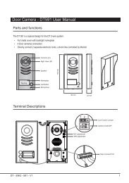
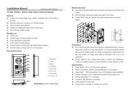
<strong>Use</strong> <strong>additional</strong> <strong>Power</strong> <strong>Supply</strong> <strong>in</strong> 2-<strong>wire</strong> <strong>System</strong>In some <strong>in</strong>stallations, if the cable is too long or it is not thick enough to provideenough voltage for each device, you may need <strong>additional</strong> <strong>Power</strong> <strong>Supply</strong> to makethe system works properly.Note: Try to adjust the PS5-24 voltage (Normally the voltage should be adjust to26V) to highest (about 27V), to check if system works. If not, you should consideruse <strong>additional</strong> <strong>Power</strong> <strong>Supply</strong>.For Monitors which are far away from the <strong>Power</strong> <strong>Supply</strong>, if be<strong>in</strong>g called or operatemonitor<strong>in</strong>g, they may turn off quickly and re-power on aga<strong>in</strong>. This is because ofthe voltage drop caused by long cable. Although the Monitor <strong>in</strong>put voltage is morethan 20V <strong>in</strong> standby situation, however, turn on the Monitor will make the voltagemuch lower.Generally, the required voltage of Monitor is about 20V after turn on, this dependson different models, the range is from 18 to 22V. Monitor with larger TFT screenwill need higher voltage.General rules for <strong>additional</strong> <strong>Power</strong> <strong>Supply</strong>:* Only PS5-24(NES-100) can be used for ma<strong>in</strong> and <strong>additional</strong> power supply* One DT-DPS (<strong>Power</strong> Separator) is also needed, and must be <strong>in</strong>ner modified first* Additional <strong>Power</strong> <strong>Supply</strong> should be <strong>in</strong>stalled near the end of the cable* To avoid <strong>in</strong>terference, connect the Earth Ground tightly.* Although the system features non-polarity, actually <strong>in</strong> the bus, power positiveand negative are still present, <strong>additional</strong> power supply must be connect accord<strong>in</strong>gto the power polarity.* Adjust both PS5-24 to have same output voltage, the difference <strong>in</strong> betweenshould be less than 0.5V voltage.* Multi Meter is needed <strong>in</strong> field, to adjust the voltage and identify the bus polarity.Steps for <strong>in</strong>stall <strong>additional</strong> <strong>Power</strong> <strong>Supply</strong>1. Modify DT-DPS, disassemble the bottom cover, and cut one side of R201Resistor (22Ohm, 2W), and then reassemble and label it.Cut one side of R201
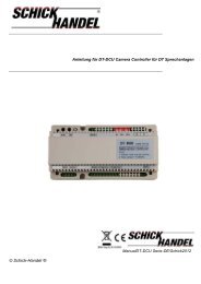
Mode 1. Basic IN-OUT wir<strong>in</strong>g ModeDABCODE=3,DIP-6=CODE=2,DIP-6=OFFECAdditional <strong>Power</strong> <strong>Supply</strong>CODE=1,DIP-6=OFFNotice Po<strong>in</strong>ts:ABMa<strong>in</strong> <strong>Power</strong> <strong>Supply</strong>ABCMeasure the output voltage of 2 powersupplies, make sure the difference is lessthan 0.5VTerm<strong>in</strong>al of PS5-24 should beconnected to the Earth GroundFor <strong>additional</strong> DT-DPS, BUS(IU) is used,and do not connect the BUS(DS)DThe <strong>additional</strong> DT-DPS should be modifiedENotice this jiont connection is withpolarity. Identify the P+ and P- withmultimeter and make sure P+ areconnceted together, P- are connectedtogether