DPSS Laser - 성경 포토닉스
DPSS Laser - 성경 포토닉스
DPSS Laser - 성경 포토닉스
- No tags were found...

You also want an ePaper? Increase the reach of your titles
YUMPU automatically turns print PDFs into web optimized ePapers that Google loves.
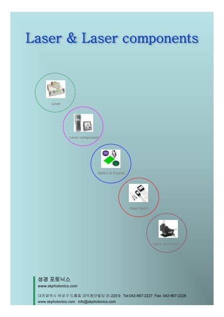
<strong>Laser</strong> & <strong>Laser</strong> components<strong>Laser</strong><strong>Laser</strong> componentOptics & CrystalFiber OpticOpto-Mechanics<strong>성경</strong> <strong>포토닉스</strong>www.skphotonics.com대전광역시 유성구 도룡동 대덕첨단빌딩 마-220호 Tel:042-867-2227 Fax: 042-867-2228www.skphotonics.com info@skphotonics.com
Contents of tableHe-Ne <strong>Laser</strong><strong>DPSS</strong> (UV, VIS, IR) <strong>Laser</strong>Nd:YAG <strong>Laser</strong>Excimer <strong>Laser</strong>Fiber <strong>Laser</strong>LD & LEDfs. ps <strong>Laser</strong>Pump <strong>Laser</strong>CO2 <strong>Laser</strong>SLD (SLED)Fiber Coupled <strong>Laser</strong>----------------- 2----------------- 6----------------- 14----------------- 18-------- 20.40.48----------------- 30-------- 36.40.4848----------------- 54----------------- 60----------------- 68----------------- 71Beam profilerBeam Position Measurement<strong>Laser</strong> Angular Deviation MeasurementVideo Microscope MeasurementSilicon PhotomultiplierHigh Resolution TimingPhoton CountingPhoton Counting EducatorAutocorrelatorPhase Resolved Pulse MeasurementSpectrum AnalyzerOptical Delay LineModelockerSingle Pulse SelectorCavity Dumper & KitOPO (Optical Parametric Oscillator)SHG, THG-------- 72.76.78----------------- 80----------------- 81----------------- 82------------ 84.86------------ 85.94------------ 85.96------------ 85.98--------------- 102--------------- 110--------------- 111--------------- 112--------------- 114--------------- 115--------------- 116--------------- 117--------------- 118
He-Ne <strong>Laser</strong>633nm (RED) LASERSModelNumberModeStructureMinimumOutputPower(mW)BeamDiameter(mm)BeamDivergence(mrad)PolarizationRatioLongitudinalModeSpacing(MHz)CDRHClassRecommendedPowerSupplyLength(mm)±1mmLHRR-0200 TEM 002.0 0.81 1.00 RANDOM 566 IIIa LPS 330.2LHRP-0201 TEM 002.0 0.81 1.00 500:1 566 IIIa LPS 330.2LHRR-0500 TEM 005.0 0.80 1.01 RANDOM 441 IIIb LPS 425.5LHRP-0501 TEM 005.0 0.80 1.01 500:1 441 IIIb LPS 425.5LHRR-1200 TEM 0012.0 0.88 0.92 RANDOM 316 IIIb LPS-H1 533.4LHRP-1201 TEM 0012.0 0.88 0.92 500:1 316 IIIb LPS-H1 533.4LHRR-1700 TEM 0017.0 0.98 0.82 RANDOM 252 IIIb LPS-H2 660.4LHRP-1701 TEM 0017.0 0.98 0.82 500:1 252 IIIb LPS-H2 660.4LHRR-0500M MULTIMODE 5.0 ~2.75 ~7.23 RANDOM 566 IIIb LPS 330.2LHRR-0800M MULTIMODE 8.0 ~1.90 ~3.98 RANDOM 441 IIIb LPS 425.5LHRR-1400M MULTIMODE 14.0 ~2.91 ~5.36 RANDOM 316 IIIb LPS-H1 533.4LHRR-1800M MULTIMODE 18.0 ~1.98 ~5.92 RANDOM 252 IIIb LPS-H1 660.4The performance of REO’s red Helium-Neon lasers has been refined through more than twenty years ofmanufacturing and continuous improvement. Improvements in cathode design, mechanical structure and mirrorquality enable REO to produce red lasers with excellent mode purity, unequaled lifetime and exceptional operationalstability.Operating Non-OperatingTEMPERATURE (C°) -20° TO +70° -40° TO +80°ALTITUDE (meters) 0 TO 3,000 0 TO 6,000HUMIDITY ≤ 80% ≤ 95%SHOCK15 g for 11 msecSTARTING VOLTAGE < 10 kVDCBEAM DRIFT AFTER 20MINUTE WARM UP< 0.2 mradLONG TERM BEAM DRIFT < 0.05 mradNOISE (30Hz - 10MHz) < 1% rms44.5 0.5 mm1/4 TurnShutterLength<strong>Laser</strong> OutputFour Holes4-40 UNC36mm Diameter Bolt Circle1.8 meter(6ft.) CoaxialCable with HighVoltage Connectorwww.skphotonics.com 2 <strong>성경</strong><strong>포토닉스</strong>
543nm (GREEN) LASERSModelNumberModeStructureMinimumOutputPower(mW)BeamDiameter(mm)BeamDivergence(mrad)PolarizationRatioLongitudinalModeSpacing(MHz)CDRHClassRecommendedPowerSupplyLength(mm)±1mmLHGR-0050 TEM 000.5 0.64 1.07 RANDOM 566 IIIa LPS 330.2LHGP-0051 TEM 000.5 0.72 0.96 500:1 416 IIIa LPS 425.5LHGR-0100 TEM 001.0 0.70 0.98 RANDOM 441 IIIa LPS 425.5LHGP-0101 TEM 001.0 0.83 0.84 500:1 303 IIIa LPS-H1 533.4LHGR-0200 TEM 002.0 0.83 0.84 RANDOM 303 IIIa LPS-H1 533.4LHGR-0050M MULTIMODE 0.5 ~1.62 ~4.02 RANDOM 566 IIIa LPS 330.2LHGR-0100M MULTIMODE 1.0 ~1.59 ~3.35 RANDOM 441 IIIa LPS 425.5LHGR-0200M MULTIMODE 2.0 ~2.58 ~4.68 RANDOM 303 IIIa LPS 533.4REO’s expertise in fabrication of low loss optics and contamination-free laser manufacturing provides a criticaladvantage in providing the highest power, longest life green Helium-Neon lasers commercially available. REO wasfounded on our history of producing the lowest loss, highest peformance laser mirrors in the world. These mirrorsare the cornerstone for the manufacture of our high performance, long-lived green Helium-Neon lasers due to theextremely low gain of the 543nm neon laser transition. Optical losses in the laser cavity are kept to an absolute minimumto maximize output power, and laser mirror degradation is minimized to maintain stable output power over the life of thelaser. Cathode preparation and gas fill are also optimized to prevent premature laser failure due to cathode sputtering.Operating Non-OperatingTEMPERATURE (C°) -20° TO +70° -40° TO +80°ALTITUDE (meters) 0 TO 3,000 0 TO 6,000HUMIDITY ≤ 80% ≤ 95%SHOCK15 g for 11 msecSTARTING VOLTAGE < 10 kVDCBEAM DRIFT AFTER 20MINUTE WARM UP< 0.2 mradLONG TERM BEAM DRIFT < 0.05 mradNOISE (30Hz - 10MHz) < 1% rms44.5 0.5 mm1/4 TurnShutterLength<strong>Laser</strong> OutputFour Holes4-40 UNC36mm Diameter Bolt Circle1.8 meter(6ft.) CoaxialCable with HighVoltage Connectorwww.skphotonics.com 4 <strong>성경</strong><strong>포토닉스</strong>
594nm (YELLOW) LASERSModelNumberModeStructureMinimumOutputPower(mW)BeamDiameter(mm)BeamDivergence(mrad)PolarizationRatioLongitudinalModeSpacing(MHz)CDRHClassRecommendedPowerSupplyLength(mm)±1mmLHYR-0100 TEM 001.0 0.67 1.12 RANDOM 566 IIIa LPS 330.2LHYP-0101 TEM 001.0 0.74 1.03 500:1 416 IIIa LPS 425.5LHYR-0200 TEM 002.0 0.72 1.05 RANDOM 441 IIIa LPS 425.5LHYP-0201 TEM 002.0 0.74 1.03 500:1 416 IIIa LPS 425.5LHYR-0100M MULTIMODE 1.0 ~1.14 ~2.83 RANDOM 566 IIIa LPS 330.2LHYR-0200M MULTIMODE 2.0 ~1.61 ~3.41 RANDOM 441 IIIa LPS 425.5LHYR-0600M MULTIMODE 6.0 ~2.59 ~4.48 RANDOM 303 IIIb LPS-H1 533.4612nm (ORANGE) LASERSModelNumberModeStructureMinimumOutputPower(mW)BeamDiameter(mm)BeamDivergence(mrad)PolarizationRatioLongitudinalModeSpacing(MHz)CDRHClassRecommendedPowerSupplyYellow and orange Helium-Neon lasers are useful in applications where specific wavelength excitation is critical.Yellow lasers in particular have many applications in biomedical instrumentation utilizing fluorescent dyes. REO’swide product range offers a high degree of flexibility in matching laser models to specific applications.Length(mm)±1mmLHOP-0201 TEM 002.0 0.75 1.04 500:1 441 IIIa LPS 425.5LHOR-0250 TEM 002.5 0.75 1.04 RANDOM 441 IIIa LPS 425.5LHOR-0150M MULTIMODE 1.5 ~1.70 ~4.14 RANDOM 566 IIIa LPS 330.2LHOR-0300M MULTIMODE 3.0 ~1.57 ~3.49 RANDOM 441 IIIa LPS 425.5LHOR-0500M MULTIMODE 5.0 ~1.90 ~4.01 RANDOM 375 IIIb LPS 482.6REO’s yellow and orange lasers offer stable, single line emission without complications from lasing on neighboringwavelength transitions. These lasers also display excellent output mode purity. This allows the OEM integrator to beconfident of stable, predictable operation in performance critical applications.OperatingNon-OperatingTEMPERATURE (C°) -20° TO +70° -40° TO +80°ALTITUDE (meters) 0 TO 3,000 0 TO 6,000HUMIDITY ≤ 80% ≤ 95%SHOCK15 g for 11 msec44.5 0.5 mm1/4 TurnShutter<strong>Laser</strong> OutputFour Holes4-40 UNC36mm Diameter Bolt CircleLength1.8 meter(6ft.) CoaxialCable with HighVoltage ConnectorSTARTING VOLTAGEBEAM DRIFT AFTER 20MINUTE WARM UPLONG TERM BEAM DRIFTNOISE (30Hz - 10MHz)< 10 kVDC< 0.2 mrad< 0.05 mrad< 1% rms<strong>성경</strong><strong>포토닉스</strong> 5 info@skphotonics
B-488 Blue Solid State <strong>Laser</strong>Model B-488-5 B-488-10Wavelength488 nm +/-2nmOutput Power 5mW 10mWSpatial Mode TEM 00 , M 2 < 1.2Power Stability
G4 DIODE PUMPED SOLID STATE LASERModel Name G4-30 G4-60 G4 plus 100 G4 plus 150 G4 plus 200 G4 plus 250Wavelength 523//532nm 523/532nm 523/532nm 532nm 532nm 532nmOutput Power 30mW 60mW 100mW 150mW 200mW 250mWSpatial Mode TEM 00 , M 2 < 1.1Longitudinal ModeSingle Longitudinal Mode (slm)Power Stability
B4 Diode Pumped Solid State <strong>Laser</strong>Wavelength473 nmOutput Power 20mW 40mWSpatial Mode TEM 00 , M 2 < 1.2Longitudinal ModeSingle Longitudinal Mode (slm)Power Stability
High Power Green (HPG) SeriesModel Name HPG2000 HPG3000 HPG4000 HPG5000Wavelength532nmOutput Power 2W 3W 4W 5WSpatial Mode TEM 00 , M 2 < 1.2Power StabilityNoiseBeam DiameterBeam DivergencePolarisation<strong>Laser</strong> Head Size (mm 3 )Power supplyControlCoolingPower requirement
<strong>DPSS</strong> <strong>Laser</strong><strong>DPSS</strong> 266nm Deep UV <strong>Laser</strong> ModuleSpecifications:ModelSDL-266-XXXTWavelength (nm)266nmAve Output Power 1-5mW 10~200mWPeak power (W) ~10 ~450Average power (mW)Average power (mW) = Single pulse energy (μJ) * Rep. rate (kHz)Ave power stability
<strong>DPSS</strong> <strong>Laser</strong><strong>DPSS</strong> 473nm Single Longitude Mode Blue <strong>Laser</strong>Specifications :ModelSDL-473-SLM-XXXOutput Power1~ 5mWWavelength473nmOperation ModeCW, TEM 00 , Single Longitude ModeBeam Diameter (1/e 2 )2.0mmPower Stability
<strong>DPSS</strong> <strong>Laser</strong><strong>DPSS</strong> 532nm Single Longitude Mode Green <strong>Laser</strong>Specifications :ModelSDL-532-SLM-XXXWavelength532nmOperation ModeCW, TEM 00 , Single Longitude ModeOutput Power1-150mWM 2 factor
<strong>DPSS</strong> <strong>Laser</strong><strong>DPSS</strong> 671nm Single Longitude Mode Red <strong>Laser</strong>Specifications :ModelSDL-671-SLM-XXXWavelength671nmOperation Mode CW, TEM 00Output Power1-10mWM 2 factor
Nd:YAG <strong>Laser</strong>sLS-2135 Pulsed Nd:YAG <strong>Laser</strong>LOTIS TII LS-2135 Nd:YAG laser is designedto provide years of trouble free operationin even the most demanding environments.The most important features of thislaser is compactness, rugged reliability andsimplicity of operation.The small size of the laser and high stability of outputcharacteristics are provided by a special design of a foldedresonator. The hard-mounted optics is virtually immune tothe thermal and physical shocks. In spite of the laser smallsize, access to and replacement of every part of laser unitsis easy and simple for use.The increased safety of lasers results from the absence ofexternal high voltage connectors. The special interlocks areused to avoid abnormal laser operation from normal mode.A diffuse close-coupled pumping chamber is utilised forefficient and uniform pumping of laser rod. The device hasbeen designed for quick and easy interchange of the flashlampwithout any re-adjustmen of the laser resonator. Theflashlamp operates in simmered mode to provide stabilityof light output and long durability.Deionized water is used in the coolingsystem. The system consistsof hermetic water pump, flow,Ø7temperature and level sensorsand water-to-air heat exchanger.Standard water purification filtersare used for long-term operationSpecificationParameterValueEnergy, mJ 1064 / 532 nm 340/ 170Pulse duration (FWHM, at 1064 nm), ns 10–12Pulse repetion rate, Hz 1–10Beam divergence, mrad 2.5Beam diameter, mm 8Jitter*, ns ±1.0Energy stability** (1064 nm), % ±2.5Size L x W x H, mm (Weight, kg)<strong>Laser</strong> headPower supplyCooling systemRemote control567 x 152 x 90 (9.5)363 x 364 x 192 (15.5)363 x 364 x 192 (12.5)105 x 175 (0.5)Power requirements Single phase, 220±20 V,50–60 Hz, 500 W* with respect to external trigger of Q-switch** shot to shot for 99% of pulses10050Ø7500450 321064 nm 532 nm SH3242…53903617152567For more informationabout LOTISwww.skphotonics.com 14 <strong>성경</strong><strong>포토닉스</strong>
Nd:YAG <strong>Laser</strong>sLS-2136 Pulsed Nd:YAG <strong>Laser</strong>LOTIS TII LS-2136 laser is a high repetitionrate Q-switched Nd:YAG laser emittingat the fundamental (1064 nm) and second(532 nm) harmonic.The telescopic stable resonator has given the benefits ofuniform beam quality, high energy and low beam divergence.The intracavity mode controlling telescope compensatesthe thermal lensing of the Nd:YAG rod and limitsthe irreducible beam divergence of laser by decreasing thetransverse mode content of the beam.There is no need for external water supply since the coolingsystem is totally self-contained with water-to-air heatexchanger.The digital display remote control can be programmed torun in either auto or manual modes. It gives you fingertipcontrol of all laser functions.SpecificationParameterValueEnergy, mJ 1064 / 532 / 355 / 266 nm 140 / 75 / 25* / 18*Pulse duration (FWHM at 1064 nm), ns 15–18Pulse repetion rate, Hz 1–50Beam divergence (full angle for 86 % of energy), mrad 0.7Beam diameter, mm ≤5.0Jitter**, ns ±1.5Energy stability*** (1064 nm), % ±3.0Size L x W x H, mm (Weight, kg)<strong>Laser</strong> headPower supplyCooling systemRemote control815 x 206 x 136 (21.0)446 x 449 x 177 (20.0)446 x 449 x 266 (23.0)105 x 175 (0.5)Power requirements Single phase, 220±20 V,50–60 Hz, 1500 W* with Harmonic Generator Assembly HG-TF** with respect to external trigger of Q-switch*** shot to shot for 99% of pulses45.5181064 nm 532 nm SH10313616017…3780206140560815For more informationabout LOTIS<strong>성경</strong><strong>포토닉스</strong> 15 info@skphotonics
Nd:YAG <strong>Laser</strong>sLS-2137 Pulsed Nd:YAG <strong>Laser</strong>LOTIS TII LS-2137 combines the compactnessof LS-2134 laser with the increased energyand small divergence due to the intracavitytelescope and special double rod laserpumping chamber, which allows operationin the mode of oscillator-amplifier with asingle power supply and a cooling system.Using the unique laser chamber design reduces undesiredparasitic oscillations that can limit output energy.The closed and rigid folded structure of laser emitter providessmall dimensions, stable and dust free operation oflaser components.The crystals of the second (KTP), third (KDP) and fourth(KDP or BBO) set in the precise temperature controlledovens and harmonic separators provide highly efficientgeneration and high spectral purity of the output radiation.There is no need for external water supply since the coolingsystem is totally self-contained with water-to-air heatexchanger.The fifth harmonic assembly (213 nm) can be accessed byusing a BBO crystal to mix the fourth harmonic with thefundamental frequency as well as to mix the second andthe third harmonics. It gives a convenient and cost effectivesource of a short UV radiation.SpecificationParameterValueEnergy, mJ1064 nm 600532 nm 330355 nm 120 / 100*266 nm 90213 nm 22**Pulse duration (FWHM at 1064 nm), ns 16–18Pulse repetion rate, Hz 1–10Beam divergence, mrad ≤0.7Beam diameter, mm ≤8.0Jitter***, ns ±1.5Energy stability**** (1064 nm), % ±3.0Size L x W x H, mm (Weight, kg)<strong>Laser</strong> headPower supplyCooling systemRemote control1037 x 236 x 136 (39.0)363 x 364 x 192 (16.5)363 x 364 x 280 (15.5)105 x 175 (0.5)Power requirements Single phase, 220±20 V,50–60 Hz, 750 W* for OPO pumping (with protective mirror, cutting back reflection)** with Harmonic Generator Assembly HG-Fifth*** with respect to external trigger of Q-switch**** shot to shot for 99% of pulses21 21 21 45.5FH TH SH266 nm 532 nm 355 nm 1064 nm103136190600 23510372369517…37For more informationabout LOTIS TII andits products visitwww.lotis-tii.comCopyright © 2006 LOTIS TII Ltd. All rights reserved. LOTIS TII, the LOTIS TII logo are trademarksof LOTIS TII Ltd. All technical parameters are based on LOTIS TII’s standard testing methods.Subject to change without notice. This material is provided for informational purpose only.Brochure design by Applied Systems Ltd. www.appsys.netwww.skphotonics.com 16<strong>성경</strong><strong>포토닉스</strong>
Nd:YAG <strong>Laser</strong>sLS-2139 Pulsed Nd:YAG <strong>Laser</strong>The unique design of power supply and lasercavity provides high output parameters andreliability. The totally self-contained coolingsystem with water-to-air heat exchangerallows laser operation in different environmentconditions.LOTIS TII LS-2139 utilizes a special stable resonatorconfiguration providing thermal lens and birefringenceBeam profile (1064 nm) in far field.compensation. All cavity spaces are sealed, thus preventingthe encroaching of harmful contamination onto opticalsurfaces.Controls are available either through a menu-driven remotecontrol or via RS232 interface. All parameter sets canbe stored and recall for different operation modes.SpecificationParameter Near TEM 00TEM 00Energy, mJ 1064 / 532 nm 75 / 40 45 / 25Pulse duration (FWHM at 1064 nm), ns 15–18 15–18Pulse repetion rate, Hz 100 100Beam divergence (full angle for 86 % of energy), mrad ≤0.7 ≤0.5Beam diameter, mm ≤4.0 ≤2.5Jitter*, ns ≤±1.5 ≤±1.5Energy stability** (1064 nm), % ≤±3.0 ≤±2.5Size L x W x H, mm (Weight, kg)<strong>Laser</strong> headPower supplyCooling systemRemote control815 x 206 x 136 (22.0)446 x 449 x 177 (22.0)446 x 449 x 266 (23.0)105 x 175 (0.5)Power requirements Single phase, 220±20 V,50–60 Hz, 2000 W* with respect to external trigger of Q-switch** shot to shot for 99% of pulses45.5181064 nm 532 nm SH10313616017…3780206140560815For more informationabout LOTIS TII andits products visitwww.lotis-tii.comCopyright © 2006 LOTIS TII Ltd. All rights reserved. LOTIS TII, the LOTIS TII logo are trademarksof LOTIS TII Ltd. All technical parameters are based on LOTIS TII’s standard testing methods.Subject to change without notice. This material is provided for informational purpose only.Brochure design by Applied Systems Ltd. www.appsys.net<strong>성경</strong><strong>포토닉스</strong> 17 info@skphotonics
Excimer <strong>Laser</strong>PSX-100An innovative multi-gas excimer laser which is both compact and portable and yet iscapable of mJ pulse energies and, with a pulse duration of only 2.5 ns, peak powers in excessof 2 mW.Compact single unit constructionAir cooledShort, high peak power pulsesEfficient discharge circuit with negligible reverse aftercurrentLong thyratron lifeHalogen compatible construction for minimal repassivationA pplicationsPhotoablation and micromachiningSemiconductor processingSurface analysis<strong>Laser</strong> ionization mass spectroscopyFluorescence spectroscopyPhotochemistryRelaxation time studiesNonlinear opticswww.skphotonics.com18<strong>성경</strong><strong>포토닉스</strong>
PSX-100S pecifications<strong>Laser</strong> Medium F 2ArF KrCl KrF XeCl XeFWavelength 157 193 222 248 308 351 (nm)Max. Pulse Energy 1 1.0 4.0 0.3 5.0 2.0 1.5 (mJ)Pulse Duration 2.5 to 5.0 (ns)Max. Peak Power 1 400 1,400 120 2,000 800 600 (kW)Max. Repetition Rate 100 (Hz)Max. Average Power 2 50 400 20 400 150 100 (mW)Pulse-to-Pulse Stability 3± 5 %Beam Dimensions (H x V) 3 x 3 3 x 3 4 x 3 3 x 4 4 x 4 4 x 4 (mm)Beam Divergence (H x V) 3 x 3 3 x 3 3 x 3 3 x 4 3 x 3 3 x 3 (mr)Timing Jitter < ± 1 (ns)Power Requirements 4Cooling110 V, 60 Hz, 1AAirPhysical DimensionsDimensions (L x W x H) 30 x 26 x 21 (cm)Weight 13.4 (kg)1Measured at 10 Hz2Measured at 100 Hz3Based on 90% of all pulses4220 V, 50 Hz option availableAll specifications are typical data and subject to change withoutnotice.WarrantyPSX-100 excimer lasers are warranted free from defects inmaterials and workmanship for 1 year from the date of delivery.rev. 1b: 01/2005Specifications subject to change without notice<strong>성경</strong><strong>포토닉스</strong> 19 info@skphotonics
Excimer <strong>Laser</strong>MSX-250With its excellent beam quality, pulse-to-pulse stability and low timing jitter, the MSX-250truly represents an affordable, high-performance, compact excimer laser, ideally suited forresearch and light industrial applications.All-metal-ceramic constructionInnovative soft pre-ionization schemeLong-life discharge circuit componentsSingle compact unitPulse energies up to 50 mJ (at 248 nm)Repetition rates to 100HzExcellent beam quality and pulse-to-pulse stabilityA pplicationsFiber Bragg grating writing<strong>Laser</strong> ionization mass spectroscopyFluorescence spectroscopyPhotochemistryPhotoablation and micromachiningSurface analysiswww.skphotonics.com20<strong>성경</strong><strong>포토닉스</strong>
MSX-250S pecifications<strong>Laser</strong> Medium F 2KrF XeCl XeFWavelength 157 248 308 351 (nm)Max. Pulse Energy 1 4 50 30 35 (mJ)Max. Repetition Rate 100 100 100 100 (Hz)Max. Average Power 2 0.35 4.5 2.5 3.0 (W)Pulse-to-Pulse Stability 3 n.m. ≤ ±2 ≤ ±2 ≤± 2 (%)Pulse Duration n.m. 15 12 15 (ns)Timing Jitter n.m. < ±2 < ±2
Excimer <strong>Laser</strong>ASX-750p rovides the research scientist or engineer with a reliable, low-maintenance,high-performance source of UV radiationSoft, corona pre-ionizationEfficient micro-particle filterLong thyratron lifePulse energies up to 360 mJ (at 248nm)Repetition rates up to 60HzExcellent beam quality and pulse-to-pulse stabilityEasy installation and operationEasy and quick gas refillingSingle-phase AC powerA pplicationsFiber Bragg grating writingSpectroscopyPhotochemistryDye laser pumpingMaterials processing investigationswww.skphotonics.com22<strong>성경</strong><strong>포토닉스</strong>
ASX-750S pecifications<strong>Laser</strong> Medium ArF KrF XeCl XeFWavelength 193 248 308 351 (nm)Max. Pulse Energy 1 220 360 270 140 (mJ)Max. Repetition Rate 60 60 60 60 (Hz)Max. Average Power 2 10 20 15 8 (W)Pulse-to-Pulse Stability 3±3 ±2 ±2 ±2 (%)Pulse Duration 20 26 27 20 (ns)Timing Jitter ±2 (ns)Beam Dimensions (V x H) 6 - 8 x 22 (mm)Beam Divergence (V x H) 2 x 4 (mr)Power Requirements 4208V, single phase, 60 Hz, 1.5 KVA max.Physical DimensionsDimensions (L x W x H) 111 x 51 x 64 (cm)Weight 165 (kg)1Measured at 10 Hz2Measured at maximum repetition rate3Based on 99% of all pulses4220 V, single phase, 50 Hz option availableAll specifications are typical data and subject to change withoutnotice.WarrantyASX-750 excimer lasers are warranted free of defects in materialsand workmanship for 1 year from the date of delivery.rev. 1b: 01/2005Specifications subject to change without notice<strong>성경</strong><strong>포토닉스</strong>23info@skphotonics
Fibre <strong>Laser</strong>Features:- Up to 1.0 mJ- Below 50 ns pulse width- Exchangeable pump laser- Additional CW operation mode- Optical power feedback detection- Including back reflection output isolator- Highly reliable laser diode pumps- Excellent beam quality (M²
Fibre <strong>Laser</strong>ML20-PL-R-OEMOptions:- Beam expander- Variety of fibre lengths- Red pilot beam for tracking- Variety of output terminations- Wavelength range 1060-1090nm- Customised specs on request- “REMO“ Remote control unit- Extended warranty- 12 V power supply- Rack 19“ versionOperating and safety considerationsThis Manlight Fibre <strong>Laser</strong> is an OEM modulemanufactured for the integration into otherequipment. The user is responsible to integrateand operate the Fibre <strong>Laser</strong> according tothe national & international laser restrictions.Manlight Fibre <strong>Laser</strong>s comply with CE, FDA& RoHS. All Manlight Fibre <strong>Laser</strong>s are patentpending.The Manlight Fibre <strong>Laser</strong>s emit both invisibleClass IV and visible Class II radiations. Directand scattered radiation can be harmful to thehuman eye. Proper laser safety eyewear mustbe worn during operation.Mechanical drawings:Parameter Value UnitOperation mode Pulsed or CW -Nominal average output power 20 WEnergy per pulse (at 20 kHz) 1.0 mJPulse duration 20 kWPulse repetition rate 20 to 100 kHzOutput power tunability 10 – 100 %Output power stability (over 1 hour)
Fibre <strong>Laser</strong>Features:- Exchangeable pump laser- Up to 50W CW of output power- Excellent beam quality (M²
Fibre <strong>Laser</strong>Options:- Extended warranty- Variety of fiber lengths- Automatic power control- Red pilot beam for tracking- Different collimating optics- Customized specs on request- Back reflection output isolator- Variety of output terminationsOperating and safety considerationsThis Manlight Fibre <strong>Laser</strong> is an OEM modulemanufactured for the integration into otherequipment. The user is responsible to integrateand operate the Fibre <strong>Laser</strong> according tothe national & international laser restrictions.Manlight Fibre <strong>Laser</strong>s comply with CE, FDA& RoHS. All Manlight Fibre <strong>Laser</strong>s are patentpending.The Manlight Fibre <strong>Laser</strong>s emit both invisibleClass IV and visible Class II radiations. Directand scattered radiation can be harmful to thehuman eye. Proper laser safety eyewear mustbe worn during operation.ML50-CW-R-OEMParameter Value UnitOperation mode CW - modulated -Nominal output power 50 WOutput power tunability 10 – 100 %Long term stability (RMS, over 1h@20°C)
Fibre <strong>Laser</strong>Features:- Up to 50W CW of output power- Excellent beam quality (M²
Fibre <strong>Laser</strong>Options:- Variety of fiber lengths- Red pilot beam for tracking- Different collimating optics- Back reflection output isolator- Variety of output terminations- Customized specs on request- Extended warrantyOperating and safety considerationsThis Manlight Fibre <strong>Laser</strong> is an OEM modulemanufactured for the integration into otherequipment. The user is responsible to integrateand operate the Fibre <strong>Laser</strong> according tothe national & international laser restrictions.Manlight Fibre <strong>Laser</strong>s comply with CE, FDA& RoHS. All Manlight Fibre <strong>Laser</strong>s are patentpending.The Manlight Fibre <strong>Laser</strong>s emit both invisibleClass IV and visible Class II radiations. Directand scattered radiation can be harmful to thehuman eye. Proper laser safety eyewear mustbe worn during operation.ML50-CW-R-TKSParameter Value UnitOperation mode CW - modulated -Nominal output power 50 WOutput power tunability 10 – 100 %Long term stability (RMS, over 1h@20°C)
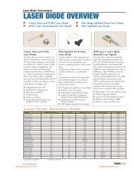
LASER DIODE OVERVIEW■ 5.6mm, 9mm, and VCSEL <strong>Laser</strong> Diodes ■ Fiber Bragg Stabilized Pump <strong>Laser</strong> Diodes■ DFB C and L-Band Butterfly <strong>Laser</strong> Pigtails ■ Fiber Pigtailed <strong>Laser</strong> Diodes5.6mm, 9mm and VCSEL<strong>Laser</strong> DiodesThorlabs offers an extensive selection ofdiscreet laser diodes in 5.6mm, 9mm andVCSEL packages. Ranging in wavelengthsfrom 405nm to 1550nm, we have a diodeto work in nearly any application. Ourselection of 5.6mm and 9mm diodesincludes both Fabry-Perot and DFB lasersin a variety of standard pin configurations.Most of our lasers are fully compatiblewith our entire line of laser diode and TECcontrollers as well as our selection of <strong>Laser</strong>Diode Mounts (See Pages 459).■ Output Powers Up to 1W■ Standard Pin Configurations■ Fabry-Perot and DFB■ VCSEL Diodes■ 405nm to 1550nm■ Compatible with Thorlabs' <strong>Laser</strong>Diode and TEC ControllersFiber Pigtailed 5.6 & 9mm<strong>Laser</strong> DiodesThorlabs’ full line of fiber pigtailed laserdiodes (manfactured by either Thorlabs orour customers) are assembled at ourextensive pigtailing facilities in the UnitedStates.A high-quality alignment process ensuresmaximum efficiency at an affordableprice.Our selection includes both single modeand multimode pigtails, whose typicalhigh-coupling efficiency delivers morepower from the diode.■ 8° Angled-Cleaved Fiber at <strong>Laser</strong> Diode■ Visible to Near IR Models■ Single Mode and Multimode Fibers■ Angle-Cleaved Fiber to MinimizeIntensity Noise (Single Mode Only)■ Pigtailing of Customer-SuppliedDiodes Available■ DFB Pigtails Include In-Line IsolatorDFB <strong>Laser</strong> C-and L-BandButterfly <strong>Laser</strong> PigtailsThorlabs offers a full range of pigtailedlasers with wavelengths centered on theITU grid (100GHz spacing). These lasersinclude polarization maintaining (PM)fiber, with an extinction ratio of better than20dB and a side mode suppression ratio of40dB (typ.). These DFB lasers meet thestringent reliability standards for thetelecom industry. With their built-in 30dBoptical isolation, thermoelectric cooler(TEC) and thermistor, these 20mW laserswill provide many hours of reliableoperation when operated with our laserdiode current controllers/TEC controllers.■ Wavelength: ITU Grid, 100GHz Steps■ Single Longitudinal Mode■ Accurate Peak Wavelength (±0.5nm)■ Built-In Optical Isolator (30dB)■ Built-In Cooler and Thermistor<strong>Laser</strong> Diode Selection GuideITEM# WAVELENGTH (nm) P (mW) PACKAGE (mm) PIN CODE PAGEDL3146-151 405 7 5.60 5B 466DL5146-152 405 35 5.60 5B 466LPS-635-FC 635 2.5 Pigtailed 9A 492HL6314MG 1,2 635 3 5.60 5A 466HL6312G 1,2 635 5 9.00 9A 467HL6335G 635 5 9.00 9A 467DL3148-025 635 6 5.60 5A 467HL6320G 1,2 635 10 9.00 9A 468HL6344G 635 10 9.00 9A 468HL6322G 635 15 9.00 9A 468DL4038-026 635 20 9.00 9A 469DL5038-021 635 35 9.00 9A 469LPM-635-SMA 635 7.5 Pigtailed 9A 492DL3147-060 650 7 5.60 5A 469GH06510B2A 654 10 5.60 5B 470RLD65MZT2 655 10 5.6 5B 470HL6501MG 1 658 35 5.60 5C 470DL6147-040 658 40 5.60 5A 471HL6512MG 658 50 5.60 OPEN 471DL7147-201 658 60 5.60 OPEN 471ML120G21 658 80 5.60 OPEN 4721 Single Mode - Longitudinal 2 Single Mode - Transversewww.skphotonics.com30<strong>성경</strong><strong>포토닉스</strong>
<strong>Laser</strong> Diode Selection GuideITEM# WAVELENGTH (nm) P (mW) PACKAGE (mm) PIN CODE PAGEHL6535MG 1 658 90 5.60 OPEN 472LPS-660-FC 660 7.5 Pigtailed 5C 492LPM-660-SMA 660 22.5 Pigtailed 5C 492ML101J8 660 45 5.60 OPEN 472HL6548FG 660 90 9.00 9D 473ML101J27 660 130 5.60 OPEN 473HL6722G 1,2 670 5 9.00 9A 473HL6724MG 1,2 670 5 5.60 5A 474DL3149-057 670 7 5.60 5A 474HL6714G 1,2 670 10 9.00 9A 474LPS-675-FC 675 2.5 Pigtailed 9A 492FLD6A2TK 685 35 5.60 OPEN 475HL6738MG 1,2 690 35 5.60 5C 475VCSEL-780 780 1.65 — – 475L780P010 780 10 5.60 5A 476GH0781JA2C 784 120 5.60 OPEN 476RLD78MA-E 785 5 5.6 5B 476LPS-785-FC 785 6.25 Pigtailed 5A 492DL4140-001S 785 25 5.60 5C 477HL7851G 1,2 785 50 9.00 9A 477DL7140-201S 785 80 5.60 5C 477L785P100 785 100 5.60 5A 478L808P010 808 10 5.60 5A 478L808P030 808 30 5.60 5A 478L808P200 808 200 5.60 5A 479L808P1WJ 808 1WATT 9 9A 479LPS-830-FC 830 10.0 Pigtailed 9C 492DL5032-001 830 30 9.00 9A 479HL8325G 1,2 830 40 9.00 9C 480DL7032-001 1,2 830 100 9.00 9A 480DL8142-201 830 180 5.60 5C 481VCSEL-850 850 1.85 — – 481L850P010 850 10 5.60 5A 481L850P030 850 30 5.60 5A 482L850P100 850 100 5.60 5A 482L904P010 904 10 5.60 5A 482L904P030 904 30 5.60 5A 483L915P1WJ 915 1WATT 9.00 9A 483L975P1WJ 975 1 WATT 9.00 9A 483VCSEL-980 980 1.85 — – 484L980P010 980 10 5.60 5A 484L980P030 980 30 5.60 5A 484L9805E2P5 2 980 50 5.60 5A 485L980P100 980 100 5.60 5A 485PL980P200 980 200 Pigtailed BFY-14Pin 485L980P200J 980 200 9 9A 491L980P300J 980 300 9 9A 486L1060P100J 1060 100 9 9A 486LPS-1310-FC 1310 2.5 Pigtailed 5D 492ML725B11F 1310 DFB 6 5.60 5D 486ML725B8F 2 1310 10 5.60 5D 487ML925B45F 1550 6 5.60 5D 487ML925B11F 1550 DFB 6 5.60 5D 492LPS-1550-FC 1550 1.5 Pigtailed 5D 492LPS-1550DFB-FC 1550DFB 1.5 Pigtailed 5D 4921 Single Mode - Longitudinal 2 Single Mode - TransverseDFBDFBDFBPIN CODES1. All specifications are typical; see individualitems for complete details.2. Pin code is based on laser pin configurationand is used to help select socket cableassemblies.Note: The 5 and 9 of the pin code designate 5.6mm or 9mm packages,respectively.<strong>성경</strong><strong>포토닉스</strong>31465info@skphotonics
Fiber Pigtailed <strong>Laser</strong> DiodesThorlabs offers a full line of fiber pigtailed laser diodes using eithersingle mode or multimode fibers. Our high-quality alignmentprocess ensures maximum efficiency.Single mode pigtails provide coherent fiber-coupled output from alaser diode. Multimode pigtails deliver higher power from thediode; however, they do not maintain coherence. Please see thebeam profile images (below) to choose the correct fiber for aspecific application.Bracket for Fiber PigtailThe PTLB1 is designed to mount easilyand conveniently a LPS or LPM Seriespigtail to either a breadboard or a TRPost. The universal design allows theL-bracket to be used with both imperialor metric components. The PTLB1has a 13/32-40 tap through thecenter of the mounting area,allowing the end user to plug thepigtail into an SR9 (ESD protection andstrain relief cable). The PTLB1 makes themounting of pigtails easy for most applications.ITEM # $ £ € RMB DESCRIPTIONPTLB1 $22.00 £13.90 €20,50 ¥ 210.10 Fiber Pigtail L-BracketFeatures■ Choice of Single Mode or Multimode Fibers■Assorted Wavelengths from Visible to Near IRCAUTION:ELECTROSTATICSENSITIVE■ Single Mode Pigtails have 8° Angle Cleaved Fiber at<strong>Laser</strong> Diode End for Minimizing Intensity Noise■ FC/PC and SMA Fiber Connectors (CustomAvailable Upon Request)■ DFB Pigtails With In-Line Single Stage Isolator■ Pigtailing Service of Customer Supplied DiodesAvailableIMPORTANT NOTES AND WARRANTY INFORMATIONON LASER DIODES/LASER PIGTAILS<strong>Laser</strong> diodes have extremely long lifetimes. However, mostfailures occur from mishandling or operating the lasers beyondtheir maximum ratings. <strong>Laser</strong> diodes are highly static sensitive.Thorlabs cannot guarantee the lasers after their sealed packagehas been opened. We will be happy to extend a full refund orcredit for any lasers returned in their original sealed packagewithin 30 days of purchase.DFBITEM # λ $ £ € RMB MODE Pmin Ptyp Pmax PIN CODELPS-635-FC 635nm $ 446.00 £ 281.00 € 414,80 ¥ 4,259.30 SM 2.0mW 2.5mW 3.5mW 9ALPM-635-SMA 635nm $ 394.00 £ 248.20 € 366,40 ¥ 3,762.70 MM 6.0mW 7.5mW 8.5mW 9ALPS-660-FC 660nm $ 446.00 £ 281.00 € 414,80 ¥ 4,259.30 SM 6.0mW 7.5mW 9.0mW 5CLPM-660-SMA 660nm $ 359.00 £ 226.20 € 333,90 ¥ 3,428.50 MM 18.0mW 22.5mW 25.5mW 5CLPS-675-FC 670nm $ 446.00 £ 281.00 € 414,80 ¥ 4,259.30 SM 2.0mW 2.5mW 3.5mW 9ALPS-785-FC 785nm $ 419.00 £ 264.00 € 389,70 ¥ 4,001.50 SM 5.0mW 6.25mW 7.5mW 5CLPS-830-FC 830nm $ 494.00 £ 311.20 € 459,40 ¥ 4,717.70 SM 8.0mW 10.0mW 12.0mW 9CLPS-1310-FC 1310nm $ 446.00 £ 281.00 € 414,80 ¥ 4,259.30 SM 2.0mW 2.5mW 3.0mW 5DLPS-1550-FC 1550nm $ 534.00 £ 336.40 € 496,60 ¥ 5,099.70 SM 1.2mW 1.5mW 1.8mW 5DLPS-1550DFB-FC 1550nm $1,711.00 £1,077.90 €1.591,20 ¥16,340.10 SM 1.2mW 1.5mW 1.8mW 5D162.5µm core Graded Index Fiber wavelength can vary from 665nm to 680nm.T O O L SOF THET R A D ENew Electro-OpticModulators■High Performance in a Compact Package■ AR Coatings Cover the400–1650nm Range■ Ø2mm Clear Aperture■ DC to 100MHzHalfwave Voltage (V)EO-AM Halfwave Voltage Vs Wavelength7006005004003002001000400 600 800 1000 1200 1400 1600 1800Wavelength (nm)MgO Doped LiNbO3 Available Upon Request – Custom OEM Versions Availablewww.skphotonics.com32<strong>성경</strong><strong>포토닉스</strong>
LDM Series <strong>Laser</strong> Diode Modules — Blue or RedThe LDM Series <strong>Laser</strong> Diode Modules are self-contained laser diode modules, available atwavelengths of 405nm and 635nm. These user-friendly devices provide collimated outputbeams and include provisions for attaching our SM1 Series optics packages to allow focusingof the collimated beam.Containing both a constant current laser diode drive system and a TEC stabilizedtemperature controller, each module offers an extremely stable CW output. The outputpower can be controlled via a user-accessible adjustment pot, a beam shutter, or an enableswitch. The enable switch is separated from the power switch, allowing the TEC controllerto maintain temperature while the laser is disabled.The LDM Series has all of the required safety features including a keylock power switch, LDM405remote interlock connection, beam shutter, and <strong>Laser</strong> ON indicator.Operating from a 9VDC power supply, included with the module, each module can be mountedto any optical table using one of our C1502, C1503, KM200V, or VC3 V-groove mounts.LDM405 SpecificationsPARAMETER MIN TYPICAL MAXWavelength (nm) 395 405 415Beam Diameter (mm)* – 3.0 x 5.0 –Power (mW) 0 – 4 (Adjustable)TEC Temperature – 25°C –*Measured 3m from module. Beam shape is elliptical.LDM635 SpecificationsPARAMETER MIN TYPICAL MAXWavelength (nm) 625 635 645Beam Diameter (mm)* - 3.0 x5.0 -Power (mW) 0 – 4 (Adjustable)TEC Temperature – 25° –*Measured 3m from module. Beam shape is elliptical.LDM635Features■ 405nm or 635nm Wavelengths■ Temperature Stabilized■ Adjustable Output Power■ IEC60825-1/CDRH Compliant■ Collimated Output Beam■ Beam Shutter■ SM1 CompatibleLDM635Shown in a KM200V, SeePage 198 for the Mount.<strong>Laser</strong> Diode Kit■■■ITEM# $ £ € RMB DESCRIPTIONLDM405 $ 3,570.00 £ 2,249.10 € 3.320,10 ¥ 34,093.50 405nm, 4.5mW Blue <strong>Laser</strong> ModuleLDM635 $ 564.00 £ 355.30 € 524,50 ¥ 5,386.20 635nm, 4.5mW Red <strong>Laser</strong> ModuleS2011 <strong>Laser</strong> Kit Comes Complete With <strong>Laser</strong>Module, Mount, and Power Supply• S2011 Power Supply: 110VAC, 50-60Hz• S2011-EC Power Supply: 220VAC 50-60HzPlug-and-Play ReadyIdeal as a General Purpose Alignment AidThe S2011 utilizes the CPS196 laser module, whichfeatures a focusable output beam. The laser diodewavelength is 635nm, and the output power is 4.5mW.Included in the kit are the post, post holder, base, andLDS1 power supply shown in the picture.Complete as Shown in Photograph.ITEM # METRIC ITEM# $ £ € RMB DESCRIPTIONS2011 S2011-EC $ 328.00 £ 206.60 € 305,00 ¥ 3,132.40 635nm, 4.5mW <strong>Laser</strong> Diode Kit<strong>성경</strong><strong>포토닉스</strong>33info@skphotonics
Light Emitting Diode Drivers Selection GuidePages 506-523ITEM# WAVELENGTH POWER VIEWING HALF ANGLE PACKAGE PAGELED341W 340nm 0.35mW 7.5° TO-39 507LED370E 375nm 2.5mW 19° T-1 3/4 507LED405E 405nm 6mW 5° T-1 3/4 507LEDC2 455nm 239.85mW - Leica DMI Microscope 508LEDC3 455nm 323.94mW - Nikon Eclipse Microscope 508LEDC4 455nm 339.19mW - Zeiss Axioskop Microscope 508LEDC1 455nm 438mW - Olympus BX & IX Microscopes 508MRMLED 455nm 730mW 75° SM1 508LED470E 470nm 8.5mW 7.5° T-1 3/4 509LEDC6 470nm 205.35mW - Leica DMI Microscope 509LEDC7 470nm 277.35mW - Nikon Eclipse Microscope 509LEDC8 470nm 290.4mW - Zeiss Axioskop Microscope 509LEDC5 470nm 375mW - Olympus BX & IX Microscopes 509MBLED 470nm 625mW 75° SM1 510LEDC10 505nm 138mW - Leica DMI Microscope 510LEDC11 505nm 186.38mW - Nikon Eclipse Microscope 510LEDC12 505nm 195.15mW - Zeiss Axioskop Microscope 510LEDC9 505nm 252mW - Olympus BX & IX Microscopes 510MCLED 505nm 420mW - SM1 511LED521M 525nm 2mW 55° TO-18 512LED525E 525nm 2.6mW 7.5° T-1 3/4 512LEDC14 530nm 90.35mW - Leica DMI Microscope 512LEDC15 530nm 122.03mW - Nikon Eclipse Microscope 512LEDC16 530nm 127.78mW - Zeiss Axioskop Microscopex 512LEDC13 530nm 165mW - Olympus BX & IX Microscopes 512MGLED 530nm 275mW 75° SM1 512LED528E 535nm 1.5mW 10° T-1 3/4 513LEDRGBE 540nm 6.2mW 12.5° T-1 3/4 513LEDC18 540nm 164.28mW - Leica DMI Microscope 514LEDC19 540nm 221.88mW - Nikon Eclipse Microscope 514LEDC20 540nm 232.32mW - Zeiss Axioskop Microscope 514LEDC17 540nm 300mW - Olympus BX & IX Microscopes 514MWLED 540nm 500mW 75° SM1 514LEDWE-15 white 1mW 7.5° T-1 3/4 515LEDWE-10 white 2.6mW 10° T-1 3/4 515LEDWE-50 white 3.7mW 25° T-1 3/4 515LED591E 590nm 2mW 10° T-1 3/4 516LED631E 635nm 4mW 10° T-1 3/4 516LED630E 639nm 7.2mW 7.5° T-1 3/4 516LED661L 655nm 1.7mW 6° TO-18 517LED661W 670nm 0.45mW 15° TO-18 517LED781W 780nm 6mW 55° TO-18 517LED780E 780nm 18mW 10° T-1 3/4 518LED851W 850nm 8mW 10° TO-18 518LED851L 850nm 18mW 10° TO-18 518LED870E 870nm 22mW 10° T-1 3/4 519LED940E 940nm 18mW 10° T-1 3/4 519LED1050E 1050nm 2.5mW 15° T-1 3/4 520LED1200E 1200nm 2.5mW 15° T-1 3/4 520LED1300E 1300nm 2mW 15° T-1 3/4 520LED1450E 1450nm 2mW 15° T-1 3/4 520LED1550E 1550nm 2mW 15° T-1 3/4 521LED1650P 1650nm 0.9mW
Light Emitting Diode TechnologiesRadiometric vs. Photometric UnitsFor many applications, light emitting diodes (LEDs) provide a low cost, reliable alternative to traditional light sources such as theincandescent light bulb, halogen bulbs, or arc lamps. Applications involving these former light sources gave rise to photometric measuresfor power, brightness, etc. Since Thorlabs typically provides radiometric specifications for our laser diodes, this overview is to serve as thebridge between the two regimes.Depending on the LED, the specifications might be given using any of the following radiometric quantities: power (also called radiantflux and measured in watts (W)), irradiance (measured in W/m 2 ), radiant intensity (measured in watts per steradian (W/sr)), and radiance(measured in W/m 2·sr). The corresponding photometric quantities, which are listed in the table below, are based on the SI unit forluminous intensity, the candela (cd). Values reported in candelas are weighted by a spectral luminous efficiency function, which representsthe human eye’s sensitivity to the light at a given wavelength. Hence, candelas are a photometric unit, thereby giving information aboutthe perceived brightness of a source; in contrast, power, irradiance, radiant intensity, and radiance are radiometric units, thus providinginformation about the absolute brightness of a source.Based on the candela, three other photometric quantities are also commonly used to specify power measurements for LEDs: luminance(measured in cd/m 2 , which is also sometimes referred to as a Nit), luminous flux (whose SI unit is the lumen (lm)), and illuminance(whose SI unit is the lux (lx)). Therefore, each radiometric quantity has a photometric counterpart, which is weighted by the spectralresponse of the human eye.To convert between radiometric and photometric units, one needs to know the photopic spectral luminous efficiency curve V(), whichgives the spectral response of the human eye to various wavelengths of light. The original curve, which is shown below, was adopted by theCommission on Illumination (CIE) as the standard in 1924 and is still used today even though modifications have been suggested.Empirical data shows that the curveQUANTITY RADIOMETRIC PHOTOMETRIC has a maximum value of unity atPower W Lumen (lm) = cd·sr 555nm, which is the wavelength oflight at which the human eye is mostPower Per Unit Area W/m 2 Lux (lx) = cd·sr/m 2 = lm/m 2sensitive, and trails off to levels belowPower Per Unit Solid Angle W/sr Candela (cd) 10 -5 for wavelengths below 370nmand above 780nm.Power Per Unit Area Per Unit Solid Angle W/m 2·sr cd/m 2 = lm/m 2·sr = nitNormalized Efficiency10.8Photopic Spectral Luminous Efficiency CurveA non-linear regression fit to the experimentaldata yields the approximation,V( λ ) = 1.019e2−285.4(λ −0.559)0.6where the wavelength is in micrometers.According to the definition for a candela, there0.4are 683 lumens per watt for 555nm light that ispropagating in a vacuum. Hence, for a0.2monochromatic light source, it is fairly simple toconvert from watts to lumens; simply multiply0the power in watts by the appropriate V() value,300 400 500 600 700 800 and use the conversion factor from the definitionWavelength (nm)for a candela.For example, the photometric power of a 5mW red ( = 650nm) laser pointer, which corresponds to V() = 0.096, is 0.096 x 0.005W x683lm/W = 0.33lm, whereas the value for a 5mW green ( = 532nm) laser pointer is 0.828 x 0.005W x 683lm/W = 2.83lm. Thus,although both laser pointers have the exact same radiant flux, the green laser pointer will appear approximately 8.5 times brighter thanthe red one assuming both have the same beam diameter.Conversion from radiometric to photometric units becomes more complex if the light source is not monochromatic. In this case, themathematical quantity of interest isΦ V= Kλ = 830m ∫ ΦEλ = 380( λ)V( λ)δλwhere v is the luminous flux in lumens, Km is a scaling factor equal to 683 lumens per watt, E () is the spectral power in watts pernanometer, and V() is the photopic spectral luminous efficiency function. Note that the integration is only carried out over thewavelengths for which V() is non-zero (i.e. = 380 - 830nm). Since V() is given by a table of empirical values, it is best to do theintegration numerically.06www.thorlabs.com<strong>성경</strong><strong>포토닉스</strong> 35 info@skphotonics,
OrigamiLow-noise soliton femtosecond laser module designed for OEM and R&D applications.• Compact, dust-sealed OEM package• One-button operation• Plug & play, maintenance free• Very high pulse quality• Pedestal free perfect sech 2 – pulses• Clean sech 2 shape optical spectrum• No Kelly-sidebands, no spectral ripple• Very low amplitude and phase noise• No amplifier built in – no ASE noise• Internal optical isolation stage• Internal monitor photodiode• Passively air cooled – no water cooling• Low power consumption• No adjustment knobs or screws• No user-serviceable parts inside or outside laser• High repeatability and stability• Full digital I/O controlSpecifications Origami - 08 Origami - 10 Origami - 15Center wavelength 765 - 785 nm 1025 - 1070 nm 1530 - 1575 nmPulse duration 1 < 160 fs < 150 fs < 180 fsAverage output power > 30 mW > 120 mW > 90 mWPulse repetition rate40 / 75 / 76 / 80 MHz (+/- 200 kHz)Spectral bandwidth transform limited (0.32)Output polarizationlinear (PER > 23 dB)Beam quality factor M 2 < 1.1Amplitude noise (24h)< 0.2% rms, 10’000Size laser head 2 306 x 112 x 54 mm 3Size laser controller 165 x 105 x 40 mm 3Power consumption< 15 WPower supply 390 – 264 VAC, 47 – 63 HzWeight laser head 22.5 kgWeight laser driver incl. power supplies 1 kg1 tunable (requires external adjustable power supply)2 exact size and weight depends on the pulse repetition rate, data for 80 MHz version3 alternatively laser can be directly attached to 5V/24V power supply4 rms phase noise < 50 fs (10 Hz - 1 MHz)5 residual amplitude noise
Optical spectrum as a function of timePower as a function of timeTemperature cycling dataFree running phase noise measurementAverage output power (mW)100806040200012PowerTemperature34Time (h)567403020100Ambient temperature (°C)Phase noise power spectr. density (dBc/Hz)-40-60-80-100-120Single-sided phase noise around 18th harmonicRMS timing jitter:100 Hz - 1 MHz: 50.5 fs10 1 10 2 10 3 10 4 10 5 10 6 10 7Offset frequency (Hz)Technical drawing of laser head (measures in mm, 80-MHz version):Technical drawing of laser driver (measures in mm):DIGITAL I/O<strong>성경</strong><strong>포토닉스</strong>37info@skphotonics
GenkiLow-noise picosecond laser module designed for OEM and R&D applications.• Compact, dust-sealed OEM package• One-button operation• Plug & play, maintenance free• Very high pulse quality• Pedestal free pulses• Clean optical spectrum• Very low amplitude and phase noise• No amplifier built in – no ASE noise• Internal optical isolation stage• Internal monitor photodiode• Passively air cooled – no water cooling• Low power consumption• No adjustment knobs or screws• No user-serviceable parts inside or outside laser• High repeatability and stability• Full digital I/O controlSpecifications Genki - 10 Genki - 15Center wavelength 1064 nm 1530 - 1575 nmPulse duration < 10 ps < 5 psAverage output power > 15 mW > 100 mWPulse repetition rate40 / 75 / 76 / 80 MHz (+/- 200 kHz)Spectral bandwidth < 0.3nm < 5 nmOutputPanda PM fiberPolarization Extinction ratio> 20 dBAmplitude noise (24h)< 0.2% rms, 10’000Size laser head 1 306 x 112 x 54 mm 3Size laser controller 165 x 105 x 40 mm 3Power consumption< 15 WPower supply 290 – 264 VAC, 47 – 63 HzWeight laser head 22.5 kgWeight laser driver incl. power supplies 1 kg1 exact size and weight depends on the pulse repetition rate, data for 80 MHz version2 alternatively laser can be directly attached to 5V/24V power supply3 residual amplitude noise
Genki - 10 HPHigh power 1-μm picosecond laser module designed for OEM and R&D applications.• Compact, dust-sealed OEM package• One-button operation• Plug & play, maintenance free• Very high pulse quality• Pedestal free pulses• Clean optical spectrum• Low amplitude and phase noise• No amplifier built in – no ASE noise• Internal monitor photodiode• Low power consumption• Air cooled – no water cooling• No adjustment knobs or screws• No user-serviceable parts inside or outside laser• High repeatability and stability• Full digital I/O controlSpecifications Genki - 10 HP ND Genki - 10 HP YBCenter wavelength 1064 nm 1030 nmPulse duration < 10 ps < 7 psAverage output power > 0.8 W > 1 WPulse repetition rate40 / 50 MHz (+/- 200 kHz)Spectral bandwidth < 0.6nm < 0.9 nmOutputcollimated free spacePolarization Extinction ratio> 23 dBAmplitude noise (24h)< 0.4% rms, 10’000Size laser head 1 230 x 196 x 54 mm 3Size laser controller 274 x 225 x 44 mm 3Power consumption< 100 WPower supply 290 – 264 VAC, 47 – 63 HzWeight laser head 25 kgWeight laser driver incl. power supplies 2 kg1 exact size and weight depends on the pulse repetition rate, data for 40 MHz version2 alternatively laser can be directly attached to 5V/24V power supply3 residual amplitude noise
PolarOnyxINVISIBLE LASER RADIATION-AVOID EYE OR SKIN EXPOSURE TODIRECT OR SCATTERED RADIATIONMAXIMUM OUTPUT: 200 J / 20WPULSE DURATION: < 1 psWAVELENGTH:900 -1100 nmCLASS IV LASER PRODUCTwww.skphotonics.com40<strong>성경</strong><strong>포토닉스</strong>
PolarOnyx<strong>성경</strong><strong>포토닉스</strong> 41 info@skphotonics
PolarOnyx!! DANGER!!LASER RADIATIONAVOID EYE OR SKIN EXPOSURE TODIRECT OR SCATTERED RADIATIONMAXIMUM OUTPUT: 0.5W CWPULSE DURATION: < 1 psWAVELENGTH:450 -1700 nmCLASS 3b LASER PRODUCTwww.skphotonics.com 42 <strong>성경</strong><strong>포토닉스</strong>
PolarOnyx<strong>성경</strong><strong>포토닉스</strong> 43 info@skphotonics
PolarOnyx!! DANGER!!INVISIBLE LASER RADIATION-AVOID EYE OR SKIN EXPOSURE TODIRECT OR SCATTERED RADIATIONMAXIMUM OUTPUT: 200 J / 20WPULSE DURATION: < 1 psWAVELENGTH:900 -1100 nmCLASS IV LASER PRODUCTwww.skphotonics.com 44 <strong>성경</strong><strong>포토닉스</strong>
Femtolite FX-60E R B I U M - D O P E D F I B E R - B A S E D F E M T O S E C O N D L A S E RF E M T O L I T E FX-60most powerful Femtolitecompact laser head (24.1 x 19.3 x 7.6 cm)portable systemadvanced designintegratablefor use in Terahertz, Multiphoton, and other OEM applicationsnominal specificationsIMRA America, Inc.1044 Woodridge AvenueAnn Arbor, MichiganUSA 481051.734.930.2560 fax 1.734.930.9957email lasers@imra.com http://www.imra.comPioneering Ultrafast Fiber <strong>Laser</strong> Technologycenter wavelength (nm)pulse duration (fs)repetition rate (MHz)average power (mW)810
FCPA µJewel D-400YTTERBIUM - DOPED FIBER - BASED FEMTOSECOND LASERF C P A µJEWEL D-400cutting-edge laser technologycompact laser head (55.0 x 40.0 x 13.3 cm)turnkey & maintenance freeno need for external coolingenhanced controlfor commercial and industrial precision micromachiningnominal specificationsIMRA America, Inc.1044 Woodridge AvenueAnn Arbor, MichiganUSA 481051.734.930.2560 fax 1.734.930.9957email lasers@imra.com http://www.imra.comPioneering Ultrafast Fiber <strong>Laser</strong> Technologycenter wavelength (nm)pulse energy (µJ)pulse duration (fs)repetition rate (kHz)*average power (mW)10432500200400* Repetition rate may be factory set between 100 kHzand 5 MHz with subsequent change in pulse energy andduration.www.skphotonics.com 50 <strong>성경</strong><strong>포토닉스</strong>
F C P A µJEWEL D-400 VARIABLE REPETITION RATEcutting-edge laser technologyFCPA µJewel D-400YTTERBIUM - DOPED FIBER - BASED FEMTOSECOND LASERcompact laser head (55.0 x 40.0 x 13.3 cm)turnkey & maintenance freeno need for external coolingadded flexibilityfor commercial and industrial precision micromachiningVARIABLE REPETITION RATE in FCPA standard laser headnominal specificationsIMRA America, Inc.1044 Woodridge AvenueAnn Arbor, MichiganUSA 481051.734.930.2560 fax 1.734.930.9957email lasers@imra.com http://www.imra.comPioneering Ultrafast Fiber <strong>Laser</strong> Technologycenter wavelength (nm)pulse energy (µJ)pulse duration (ps)variable repetition rate (MHz)*average power (mW)1043* Repetition rate may be varied/ set between 200 kHzand 5 MHz at up to 15 customer selected, factory setvalues.2
FCPA µJewel D-1000YTTERBIUM - DOPED FIBER - BASED FEMTOSECOND LASERF C P A µJEWEL D-1000cutting-edge laser technologycompact laser head (55.0 x 40.0 x 13.1 cm)turnkey & maintenance freeno need for external coolingmore energyfor commercial and industrial precision micromachiningHigher energy pulses based on IMRA’s proven FCPA technologyHigh energy version: 10 µJ @ 100 kHzHigh repetition rate version: 1 µJ @ 1 MHznominal specificationsIMRA America, Inc.1044 Woodridge AvenueAnn Arbor, MichiganUSA 481051.734.930.2560 fax 1.734.930.9957email lasers@imra.com http://www.imra.comPioneering Ultrafast Fiber <strong>Laser</strong> Technologycenter wavelength (nm)pulse energy (µJ)pulse duration (fs)repetition rate (kHz)*104510700100* Repetition rate may be factory set between100 kHz and 5 MHz with subsequent change inpulse energy and duration.www.skphotonics.com 52 <strong>성경</strong><strong>포토닉스</strong>
FCPA µJewel D-3000YTTERBIUM - DOPED FIBER - BASED FEMTOSECOND LASERF C P A µJEWEL D-3000cutting-edge laser technologycompact laser head (55.0 x 40.0 x 13.1 cm)turnkey & maintenance freeno need for external coolingmore powerfor commercial and industrial precision micromachiningHigher energy pulses based on IMRA’s proven FCPA technologyHigh energy version: 10 µJ @ 200 kHzHigh repetition rate version: 3 µJ @ 1 MHznominal specificationsIMRA America, Inc.1044 Woodridge AvenueAnn Arbor, MichiganUSA 481051.734.930.2560 fax 1.734.930.9957email lasers@imra.com http://www.imra.comPioneering Ultrafast Fiber <strong>Laser</strong> Technologycenter wavelength (nm)pulse energy (µJ)pulse duration (fs)repetition rate (kHz)*average power (mW)1043107002003000* Repetition rate may be factory set between 100 kHzand 5 MHz with subsequent change in pulse energyand duration.<strong>성경</strong><strong>포토닉스</strong> 53 info@skphotonics
14-pin Package Dimensions14-pin Package Pinout6 x 2.54 = 15.214 x 0.5Fiber length1.5 m nominal5.4TEC + 1+TEC–14 TEC –12.7 8.89Thermistor 2Thermistor13 Case ground13.94 x Ø2.7Monitor anode – 3Monitor cathode + 4Monitor12 NC11 <strong>Laser</strong> cathode –20.526.030.044.8 nomThermistor 5NC 6<strong>Laser</strong>10 <strong>Laser</strong> anode +9 NCNC 78 NC7.61.04.4All units in mm6-pin Package Dimensions6-pin Package Pinout2 x 2.54 = 5.08Fiber length 1.5m nominal5.02x 2.4Thermistor6 Thermistor40.0 19.013.58.05 ThermistorNC 14 <strong>Laser</strong> cathode –16.0<strong>Laser</strong> anode + 2<strong>Laser</strong>10.06 x 1.3NC 315.034.4 nominalNOTE: LASER POLARITY ISREVERSED FROM PREVIOUSALFALIGHT 6-PIN PACKAGES5.43.01.02.5C-mount Package DimensionsQ-mount Package Dimensions2.181.06.35±.10010θθ0.158.04.0<strong>Laser</strong>output2.8Case isanode (+)Counterbore1.3 deep4.62.40All units in mm1832 Wright Street • Madison, WI 53704 • 608.240.4800 telephone • 608.240.4801 facsimile • alfa-sales@alfalight.comCopyright © 2007 Alfalight, Inc. QS4246 v1.1<strong>성경</strong><strong>포토닉스</strong> 55 info@skphotonics
14-Pin 976 nm Butterfly, Industrial-GradeAlfalight’s 976 nm industrial-grade high-power multimode diode lasers areideal for cladding-pumped EDFAs and <strong>DPSS</strong> applications. The hermetically-sealed,epoxy-free 14-pin package with integrated thermoelectric coolerallows ease of use through user-controlled temperature tuning.• Hermetically-sealed package with thermoelectric cooler• Integrated monitor photodiode• Up to 4 watts output powerDevice Characteristics*AM4-976A-10-403Electro-Optical Symbol Min Typ Max UnitsCenter wavelength λ c 976 ± 3 nmOutput power P o 4.0 WOperating current I o 5.7 7.0 AForward voltage V f 1.7 1.85 VThreshold current I th 0.3 0.5 ASpectral width, FWHM Δλ 3.5 4.5 nmMonitor PhotodiodeDetector responsivity dI pd /dP o 125 625 1250 μA/WDetector reverse bias V r 0 5 VDetector dark current I dc 0.1 50 nAThermo-Electric CoolerThermistor value at 25°C R th 9.5 10 10.5 kΩThermistor constant, 0 - 50°C β 3892 KSpectral shift with submout temperature 0.3 nm/°CTEC drive current** I TEC 2.1 4.5 ATEC drive voltage** V TEC 2.1 4.9 VHeating/cooling capacity ΔT –65 40 °CMechanicalCase operating temperature T –40 65 °CCase storage temperature –40 85 °CFiber core diameter 105 μmFiber numerical aperture NA 0.15 N/AFiber length 1.0 1.5 mFiber pull strength 1.0 kg-fModule power dissipation** 10.1 17.7 W* All conditions are at 25ºC submount temperature and output power unless otherwisenoted.** Depends on mounting condition, at ΔT Maxwww.skphotonics.com 56 <strong>성경</strong><strong>포토닉스</strong>
808nm High-Efficiency Single EmittersAlfalight’s “generation B” 808 nm pump lasers offer low threshold, highslope efficiency, and excellent stability over temperature. The fi ber-coupleddevices offer 5.0 watts ex-fi ber in high-reliability uncooled packages withhigh-brightness 200 μm, 0.15 NA fi ber. Alfalight’s 6-pin package is GR-468compliant.NEW!Features• 5.0 W Output• Fiber-coupled 200 μm / 0.15 NA• High Reliability• Environmentally-ruggedApplications• Nd:YAG and Nd:YVO 4 microlasers• <strong>Laser</strong>-initiated ordnance• End-pumped <strong>DPSS</strong> lasers• Thulium-doped fiber laser pumpingDevice Characteristics*AM6-808B-60-503Electro-Optical Symbol Min Typ Max UnitsCenter wavelength λ c 804 808 811 nmOutput power P o 5.0 WOperating current I o 5.7 AForward voltage V f 1.75 1.8 VThreshold current I th 0.9 ASpectral width Δλ 3.0 5.0 nmTemperature and Thermoelectric coolerThermistor value at 25°C R th 9.5 10 10.5 kΩThermistor constant, 0 - 50°C β 3892 KSpectral shift dλ/dT 0.26 nm/°CMechanicalCase operating temperature 0 50 °CCase storage temperature -40 85 °CFiber core diameter 200 μmFiber NA NA 0.15Fiber length 1.25 1.5 1.8 m* All conditions are at 25°C submount temperature and output power unless otherwise noted.All Temperatures T refer to package thermistor temperature.<strong>성경</strong><strong>포토닉스</strong> 57 info@skphotonics
10 Watt 6-Pin 940 nmUncooled PumpsThe Alfalight AM6-940B-20-108 (10 watt, 940 nm) is an uncooledmultimode laser in a 6-pin package incorporating a thermistorfor temperature monitoring. This device is ideal for numerous industrialapplications, including pumping fi ber lasers, diode-pumped solid statelasers, uncooled fi ber amplifi ers; and direct material processing.NEW!• 940 ± 8 nm wavelength• Up to 10 watts output power• High brightness 105μm/0.22 † NA fiber• Hermetic, epoxy-free package• High reliabilityDevice Characteristics*Electro-Optical Symbol Min Typ Max UnitsCenter wavelength λ c 932 940 948 nmOutput power P o 10 WOperating current I o 11 AForward voltage V f 1.85 2.2 VThreshold current I th 0.45 0.6 ASpectral width Δλ 4.0 nmTemperatureThermistor value at 25°C R th 9.5 10 10.5 kΩThermistor constant, 0 - 50°C β 3892 KSpectral shift dλ/dT 0.33 nm/°CMechanicalCase operating temperature T 0 50 °CCase storage temperature –40 85 °CFiber core diameter 105 μmFiber NA NA 0.22 †Fiber length 1.25 1.5 1.8 m* All conditions are at 25°C submount temperature unless otherwise noted.† 0.15 NA is also available upon requestwww.skphotonics.com 58 <strong>성경</strong><strong>포토닉스</strong>
30W Combined Power Module IIIStandard and Wavelength StabilizedNEW!The CPM-III products are ideal high-brightness pump sourcesfor end-pumped <strong>DPSS</strong> lasers for Nd:YAG or Nd:YVO 4.The compact 3.35 × 2.73 × 0.67 inch module comes witha temperature monitoring thermistor. Alfalight’s proprietaryWavelength Stabilization Technology, available onAC3-808BW-68-301, minimizes wavelength shift overtemperature and can be air-cooled, simplifying thermalmanagement. Lifetime exceeds 20,000 hours.Features• 30 watts output• Single-emitter lasers architecture• 685 μm / 0.15NA fiber bundle• AR Coated SMA 905 output• Integrated thermistor• Compact 3.35” × 2.73” × 0.67” module• MTTF > 20,000 HoursApplications• End-pumped industrial <strong>DPSS</strong> lasers• Material processing & cutting• Light welding• Marking and printing• Pulsed and CW operationWavelength Stabilization Technology• Chip-level integrated semiconductor grating• Narrow linewidth (0.8 nm)• Wide locking range (ΔT > 30°C)Device Characteristics*Optical Performance - Pump Symbol AC3-808B-68-303 AC3-808BW-68-301 UnitCW optical output power P o 30 30 WCenter wavelength, operating λ c 808 ± 3 808 ± 1.5 nmSpectral shift, over case temperature dλ/dT 0.26 0.07 nm/°CSpectral shift, over case power dλ/dP N/A 0.3 nm/WSpectral width, FWHM Δλ 4.0 0.8 nmLocking range over temperature** T N/A 15 - 45 °CLocking range over power P o N/A 8 - 32 WOutput fiber685 μm / 0.15 NA bundleFiber armor3 mm Interlocked Stainless Steel TubeConnector AR Coated SMA 905Electrical-Optical Performance-PumpOperating current I o 5.0 (typical) 6.0 (typical) AOperating voltage V o 11.8 (typical) 12.3 (typical) VOperating mode R s CW or pulsedThermal PerformanceCase operating temperature T 0 - 50 0 - 50 ºCPower Dissipation 29 (typical at 25ºC) 44 (typical at 25ºC) WCooling RequirementsAir-Cooled or Water-Cooled Heatsink* All conditions are at 25°C submount temperature and output power unless otherwise noted.** Power outside of 804-812 nm range is less than 10% of the total power.<strong>성경</strong><strong>포토닉스</strong> 59 info@skphotonics
• 10, 25 & 50W models• Low cost design• Rugged & reliable• Proven operating lifetimes > 45,000 hoursSynrad’s- setting the industry standardSynrad’s original “all-metal” tube technology openedthe door for sealed CO 2 lasers in many industrialapplications. After 15 years, it remains the industrystandard for performance, reliability, long lifetime,and low cost.The laser tube is a rigid box structure design thatprovides an ultra-stable platform for the laserresonator. Synrad’s 48-series tubes are mounted intoan H-shaped heat sink extrusion that also serves asthe chassis for the drive electronics. This guaranteesthat the laser will withstand the harsh requirementsof modern industrial environments.The all-metal sealed tube design and proprietarymanufacturing process ensure high gas purity, essentialfor long operating lifetimes. With over 70,000 Synradlasers operating worldwide, Synrad is the only CO 2laser manufacturer that can boast of proven operatinglifetimes in excess of 45,000 hours (at which time,a simple and inexpensive gas refill returns the laserto full operation).Synrad lasers can be operated from 0 - 100% dutycycle, with laser power adjusted using a pulse widthmodulation (PWM) control. The laser is controlleddirectly with a TTL signal (rear-mounted BNCconnector). Alternatively, a DB-9 connectorprovides remote access to all laser functions, includinglaser control, fault conditions monitoring, remoteinterlock, and failure shutdown options.All 48-series lasers operate from standard 30VDCpower supplies, and can be either fan-cooled (48-1and 48-2 models) or water-cooled.With output powers of 10, 25, or 50W, and availablein either OEM or keyswitch configurations, Synrad’s48-series lasers are ideal for incorporation intomarking, engraving, and small cutting systems, whereperformance, low price and high reliability areessential.®An Excel Technology Companywww.skphotonics.com 60 <strong>성경</strong><strong>포토닉스</strong>
POWERON5 SEC DELAYCTRL 1 CTRL 2LASEPOWERSTATUSPWRCARBON DIOXIDE LASERLASEFUSE 1 FUSE 2LASE1.125OPTIONAL ACCESSORIESPOWER OUPUT• SpecificationsModel 48-1(S) 48-1(S)W 48-2(S) 48-2(S)W 48-5(S)WOutput Power10W25W50WMode QualityTEM 00 , 95% PurityM 2
• 100, 125, 200, & 240W models• Proven operating lifetimes > 45,000 hours• Rugged design for industrial environments• Excellent long term power stability• Superior wavelength stabilityseries - high power in a robust packageExtending our “all metal” technology to higherpowers by using a folded resonator design, theevolution series provides users with output powersfrom 100 to 240W.The all-metal sealed tube design and proprietarymanufacturing process ensure high gas purity,essential for long operating lifetimes. With over50,000 Synrad lasers operating worldwide, Synradis the only CO 2 laser manufacturer that can boastof proven operating lifetimes in excess of 45,000hours (at which time, a simple and inexpensive gasrefill returns the laser to full operation).The rugged construction of the evolution lasersguarantees high performance and reliability, and thelong cavity length provides an inherent power andwavelength stability critical to many applications.Synrad lasers can be operated from 0 - 100% dutycycle, with laser power adjusted using a pulse widthmodulation (PWM) control. The laser is controlleddirectly with a TTL signal (rear-mounted BNCconnector). Alternatively, a DB-9 connectorprovides remote access to all laser functions, includinglaser control, fault conditions monitoring, remoteinterlock, and failure shutdown options.The evolution series combines a laser head with aseparate 19” rack-mount RF power supply - 5m RFand control cables are supplied as standard. Synradevolution lasers operate from standard 30VDC powersupplies, and all models feature an electromechanicalsafety shutter.With output powers of 100, 125, 200, and 240W,the evolution series lasers are available in eitherkeyswitch or OEM versions. The 200 & 240Wmodels, because of their Duo-Lase configuration,produce a randomly polarized beam, making themespecially well-suited to cutting applications. Therugged design of these lasers makes them ideal formounting on robotic arms or moving gantry systems.Applications include acrylic and die-board cutting,machining of thin metals, and high speed codingand marking.®Synrad, Inc. 4600 Campus Place Mukilteo, Washington 98275 USAtel 1.425.349.3500 • fax 1.425.349.3667 • email synrad@synrad.com • www.synrad.comAn Excel Technology Companywww.skphotonics.com 62 <strong>성경</strong><strong>포토닉스</strong>
• SpecificationsModel Evo 100(S) Evo 125(S)Evo 200(S) Evo240(S)Output Power 100W 125W 200W 240WMode Quality TEM 00 , 90% Purity TEM 00 , 90% Purity TEM 00 , 90% Purity TEM 00 , 90% PurityM 2
www.skphotonics.com 64 <strong>성경</strong><strong>포토닉스</strong>
INVISIBLE LASER RADIATIONAVOID EYE OR SKIN EXPOSURE TODIRECT OR SCATTERED RADIATIONCLASS 4 LASER PRODUCT<strong>성경</strong><strong>포토닉스</strong> 65 info@skphotonics
• 100, 200, and 400W models• Near-Perfect beam quality• Integrated RF supply• Ruggedized, 3-point mounting systemfirestar -series - fully integrated CO2 lasersfor demanding industrial applicationsContinuing our 20 year tradition as the world’s leadingprovider of sealed CO 2lasers, Synrad has developed thefirestar f-series to meet the challenges of a globalmanufacturing marketplace by providing a new standardof performance, price, and reliability.With fully integrated RF supplies and clean, simpleinterfaces to water-cooling and control signals, the firestarf-series speeds the time for integration while providingthe maximum flexibility for system designers, OEMmanufacturers, and full turnkey system providers.Operating from a single low-cost 96 VDC power supplyand measuring a mere 25.1 inches in length, the firestarf100 is the industry’s smallest fully RF integrated 100Watt laser. By giving the system architect the bestcombination of size, simple interfaces and industry provenSynrad technology, system integration and time tocustomer delivery are minimized.To create the 200 Watt f200, Synrad’s industry provenDuo-Lase® technology was used to combine two f100lasers into a single package. The randomly polarized beamof the f200 makes it ideal for applications where kerfcontrol is critical. Measuring only 28.8 inches long, thef200 provides all the performance of a much larger laserwith the convenience of a single, compact laser source.For users needing 200 Watts of power in a linearly polarizedbeam, Synrad has created the single tube firestar f201.Featuring a near perfect output beam in the near and farfield as a result of internal beam conditioning, andincluding built in gas purge capabilities incorporated intoa robust package, the f201 has the power and performancefor the toughest of industrial jobs.When the application requires maximum power, Synradcustomers can choose the 400 Watt firestar f400. With aBeam Quality Number (M 2 ) that approaches theoreticallimits, the f400 delivers more focused continuousprocessing power than any sealed CO 2laser on the markettoday. Compared to other laser solutions that specify 500Watts of average power, but with poorer beam quality,the firestar f400 delivers an additional 23% of focusedenergy density. This difference makes traditional Wattbased comparisons obsolete.As Synrad’s newest generation of industrial laser solutions,the firestar f-series sets the standard for the industrial lasermarket. With the best combination of size, price,performance and reliability, the firestar f-series can do thejob for you.Synrad, Inc. 4600 Campus Place Mukilteo, Washington 98275 USAtel 1.425.349.3500 • fax 1.425.349.3667 • email synrad@synrad.com • www.synrad.comwww.skphotonics.com 66 <strong>성경</strong><strong>포토닉스</strong>
• SpecificationsModel f100 f200 f201 f400Output Power 100W 200W 200W 400WMode Quality TEM 00,95% Purity TEM 00,95% Purity TEM 00,98% Purity TEM 00,98% PurityM 2
www.skphotonics.com 68 <strong>성경</strong><strong>포토닉스</strong>
Superlum Diodes, Ltd.Pilot4-AC: 110/220V AC SLD ControllerFeatures:• driving of all types of cooled modules of SUPERLUM• stabilization of SLD temperature at any value within range of+10 °C to +40 °C, with indication of the set temperature• stabilization of SLD direct current at any value from 0 mA to400 mA with indication of the set current value. Highercurrent ranges are available on request• Remote control of SLD status and its on/off by external logic• High level of SLD protection against overloading• Low noiseAccessories:- Mounts for modules (DIL, BUT, TOW)- Connecting cables- External low pass filterStability and noiseAll PILOT controllers allow excellent stability of SLD modules; typical short-term (15 min, 22±0.1 °C ambient) and long-term(3 h, 22±0,5 °C) stability of SLD modules driven by PILOTs is 500 ppm and 3000 ppm, correspondently.No any excess noise to SLD intensity noise is added by PILOT-4 in frequency range 0,05-10 MHz; external LPF allows noexcess noise starting 1 KHz frequency.Technical parametersCurrent source, constant current modeSLD protection sectionSLD current range*0…400mASLD voltage, maximum 3V SLD current limit range* 5…400mASet resolution ** 0,1mA Set resolution** 0,1mAAccuracy (50-400mA) 0,5mA Accuracy (50-400mA) 1mATEC controller sectionPD monitor sectionThermistor range 6,000 …19.999kOhmStabilization T range*** 10-40°C PD monitor reverse voltage 5 VAccuracy 0,1°C PD monitor current range 0…..20mAMaximum TEC current 1200mA Display resolution 0.001mAMaximum TEC voltage 5,0V* - up to 500 mA upon request** - corresponds to LCD resolution***- it is considered that 10K3CG2 of BetaTherm Ltd. Thermistors are used in SLD modulesGeneral DataSupply voltage 110/220 V,Cable connectors9 pin D-SUBOperating temperature 0…+40 °CWeight1.2 kG<strong>성경</strong><strong>포토닉스</strong> 69 info@skphotonics
www.skphotonics.com 70 <strong>성경</strong><strong>포토닉스</strong>
Fiber Coupled Semiconductor <strong>Laser</strong>Features◆ Plug & Play◆ ESD Protection◆ Power Adjustable◆ LD Current Full Protection◆ LD Temperature Stabilized◆ Compact SizeApplications◆ Bio Technology◆ Semiconductor◆ Medical◆ Scientific◆ Photo FinishingOption◆ Polarization Maintaining Fiber◆ High Speed Modulation◆ Remote Control◆ Collimated & Focused Beam◆ Metal Jacket ProtectionThe <strong>Laser</strong> Module is a temperature stabilized semiconductor lasercoupled with single mode fiber. It features very low M2 valueGaussian beam output with excellent beam pointing stabilityat a wide temperature range.The <strong>Laser</strong> Module is a ClassⅢb laser product.Performance SpecificationsParameter Condition units TypicalWavelength T=25℃ nm 375 405 440 473 635 658 785 830Power T=25℃ mW 4 23 20 10 15 / 23 25 / 50 15 / 50 20Noise(RMS) 10~20MHz % 0.1Power Stability 1hrs, T=25℃ % 0.25Power Stability 24hrs, T=25℃ % 0.75PER dB min. 15M2 max. 1.1Beam dia. I/e2 mm 0.7 / 0.9 / 1.5 / 2.0 / 4.0 / 6.0Beam Divergence full angle mrad max. 1Pointing Stability 2hrs, T=25℃ urad max. 5Fiber TypeSM / PMOrdering Information<strong>성경</strong><strong>포토닉스</strong> 71 info@skphotonics
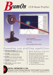
BeamOn HR1.4 Megapixel CCD Beam Profiler12 Bit resolutionMain Applications:Monitor multiple beams’ centroidsQC of lasers<strong>Laser</strong> beam analysis: Profile, beam size, position, powerExpanding your profiling capabilitiesAccurate: High resolution CCD having 12 bittrue dynamic rangeVersatile: A complete test station measuringProfile, Power and Position, both for CWand pulsed beamsPortable: Based on a USB 2.0 interface fornotebooks (or desktops)Easy to use: user-friendly software, on-linehelp routineAccessories: Complete set for larger beamsand high power attenuationMain Software FeaturesReal time beam size and gausian fit (or top hat)2D/3D plots of beam in real timeBeam centroid tracking and chart with timeSoftware controlled electronic shutter & gainVideo with playback, snapshot filesData exporting to another computer via RS232or TCP/IPData logging with detailed statisticsActiveX package to control software from yourapplicationAutomatic Pass/Fail analysis reportwww.skphotonics.com 72 <strong>성경</strong><strong>포토닉스</strong>
Software FeaturesBeam Profiles and WidthHorizontal Profile with overlaid Gausian ProfileTwo types of profile presentations are offered:Sum Profiles-Display the two orthogonal profiles, one along thevertical axis and one along the horizontal axis. Each profile iscomposed of a summation of rows and columns at a cross-section.Line Profiles-Display the beam contour along a line parallel to thevertical and horizontal axes. These two orthogonal lines aredesignated as a cross hair cursor on the image plane and can bemoved along the working area. It is possible to rotate the line profilesby +/-50 degrees for analyzing the intensity profile along a certainline and angle of interest.Best fit resultsBeam width resultsBeam widths are digitally displayed for any three user selected cliplevels. Two vertical bars can be moved along the horizontal axisdesignating the distance (in mm) along this axis.A Gausian fit profile can be overlaid on the profiles in real time,while the correlation and fit values are displayed digitally. A Top Hatprofile presentation and best fit is also available.The software offers various algorithms for beam widthcalculation:Percent of Peak84/16 Knife Edge -90/10 Knife Edge2D and 3D Intensity PlotsThe Projection function provideseither a 2D or a 3D plot of the beamintensity profile. A zooming featureenables magnification of thedisplayed image. For a weak beamimage, even at max shutter and gainsettings, optimize colors using theside color bar.Power Measurement3D Projection enables viewingthe 3D plot with projectedimages over the X and Yaxes.3D Plot-top view3D Plot3D Plot-side viewThe 2D/3D plots can berotated along the beamoptical axis, as well as beflipped. This feature enablesthe user to view the imagefrom various angles aroundthe beam.The beam power is displayed as a digital readout at the status bar,as well as at the right-hand screen panel, where there is also adisplay of the “Z” digital value in a specific cursor location (in 8 bitsor 12 bits).Alternatively, a needle-type display is available with additionalfeatures like: changing power measuring units, averaging, loadinga pre-defined filter file, ambient light suppression.A power calibration function allows the user enter a “base” powervalue. In subsequent captured images the summed intensity of allpixels will be proportional to this value.<strong>성경</strong><strong>포토닉스</strong> 73 info@skphotonics
Software FeaturesBeam Position & ChartThe beam centroid is continuously monitoredrelative to the center of the CCD head. ThreeRegions of Interest (ROI) can be defined bythe user, thus enabling to monitor of up to3 beams’ centroids simultaneously. Thedisplay includes the values of X and Y (inmm) as well as R, which is the distance from the CCD center.Trace On/Off feature enables beam centroid tracking.Chart Position function is used to display changes in the position(X and Y) with time, with autoscalling and saving capabilities.Reticule type targets can be laid outon the position screen, for ease ofpositioning analysis. The followingtargets can be used: Cross, Circle,Square, multiple circles and multiplesquares.Detailed StatisticsThe information in Statistics screen is updated in real time and isuseful for analyzing beam characteristics. It lists the information ina table format and shows the actual measurement values, as wellas the minimal measurement, the maximal measurement, theaveraged value, and the standard deviation of several parameters:Beam CentroidBeam PeakBeam width at 3 clip levelsCorrelation to Gausian profilePowerBeam finding Module – TargetA special feature, which faciliatesfinding your area of interest withinthe total CCD area. It is derived fromthe high-resolution CCD feature,where the resolution is much higherthan the screen display capabilities. Your area of interest is clearlydisplayed as a small rectangular frame within a picture representingthe CCD module. Move the small rectangle frame to explore otherportions of the CCD area.Analysis,QA Testing & ReportThe elipse function calculated the best fit ellipsoid for the examinedbeam. The major and minor axes of the fit elipse are calculates aswell as the orientation of the major axes of the fit.The distance measurement function calculates the distancebetween any two points on the beam image, the points are beingselected by the user.The Test routine allows the user to test a laser beam based onuser-defined Pass/Fail criteria. The test results are calculated forany one of the beam selected parameters.A wealth of beam analysis featuresData logging to a Text file, or to an Excel fileAveragingZoomingPrinting of Text and picturesUser set threshold levelsFull on line Help routineLive Snapshot files replay for complete analysis of resultsCapture up to 12 still images and tile them in matrix formatSophisticated report in Excel format including mixed text & imagesFull session recordings for off-line analysisCustomer set Pass/Fail criteriaExternal trigger controlewww.skphotonics.com 74 <strong>성경</strong><strong>포토닉스</strong>
SpecificationsPower ConnectorPower LED2x 3.45 108-32 UNC 6USB ConnectorRCATrigerIn5.3 Ref.ND-FILTAdaptor &NG filtersRDCBeamOnHR73.539 Ref.35336453.8 Ref.Dimentions are in mmCCD Head DrawingM37x0.75StackablefiltersSAM1MountBSAM2Full accessories setAdaptor &NG filtersAccessories combinationCCD Head SpecificatiosCamera Type: Monochrome interline transferprogressive scan, 1.4 Megapixel CCD½” formatPixel size:4.65µmX4.65µmSensor active area: 7.6mmX6.2mmWeight:165 gr.Trigger in:RCA female jack, 4.5V square wave TTLPower consumption: 6V, 4WattsMounting threads: M30x0.75 and 1”X32 (C-Mount)Accessories included: 3XND 1.8 filters in housing about 500:1,mounting post, adaptor ring for filtersGeneral SpecificationsPC interface: High speed USB2.0 (480Mbits/sec)RS232: Data outOperating temp: 0ºc to 50ºcHumidity: 5% - 95% non-condensingCE complianceHost computer RequirementsPentium IV 2GHz , 512MB RAM , 10MB Free HDD64MB 24 bit color VGA card, resolution (min) 1024x768,1 Free High Speed USB2.0 port, CD ROM any type, Win XPSystem performance with softwareSpectral response: 350-1310nmMax frame rate: 15fps at 1392x1040, 30 fps with binning (2X)Image resolution: 1392X1040Shutter speed: 0.6sec to 1µsecGain control: X1 to X23Dynamic range: 60DB not including filtersDamage threshold: 50W/cm 2 with filtersSensitivity: 5nW/cm 2 @ 633nm, 60µW/mm 2 @ 1310nmSaturation: 2mW/cm 2Operation with Ability to capture and replay images frompulsed lasers: slowly pulsing lasers (1-100Hz) whilefiltering out frames with no laser pulse.Provision for displaying single shot pulses.Hardware triggering: in pulsed mode set threshold by slide barto display frames with captured pulsesOrdering InformationBeamOnHR The system comes with a camera, a standardUSB2.0 cable, a post, a set of 3XND filters inhousing, power supply 6V DC, software on CDdisk, carrying case.Accessories:SAM1 Beam sampler (ratio 3X10 (-3) )SAM2 Beam sampler (ratio 1X10 (-6) )RDC Beam reducer (ratio 2.5X1)MountB Mounting baseND-FILT 1 /8 ND filter, M37X0.75NG-Filters 1.6mm thick Schott colored filter in mount withadaptor, types: NG4 / NG9 / NG10Acc-Set Full set of accessories (see sketch)<strong>성경</strong><strong>포토닉스</strong> 75 info@skphotonics
CCD Beam ProfilerMain Applications:- <strong>Laser</strong> beam analysis:Profile, beam size, position, power- QC of lasers- Monitor multiple beams’ centroidsExpanding your profiling capabilitiesPatented technology: Wide dynamicrange enabled by double sampling technologyVersatile: A complete test station,measures both CW and pulsed beamsFlexible: A wide spectral response fromdeep UV (190nm), VIS and up to 1550nmPortable: Based on a USB 2.0 attachment fornotebooks, or on a PCI cardEasy to use: user-friendly software,on-line help routineMain Software FeaturesReal time beam size and gaussian fit2D/3D plots of beam in real timeSoftware controlled electronic shutter & gainVideo with playback, snapshot filesData exporting to another computer via RS232Data logging with detailed statisticsActiveX package to control softwarefrom your applicationAutomatic Pass/Fail analysis reportwww.skphotonics.com 76 <strong>성경</strong><strong>포토닉스</strong>
SpecificationsCCD Head Drawing:64UN 3/4”-32Stackablefilters8.5RCAOUTSyncC-mount toUN 3/4”-32Converter48 Ref.34.34.6CCD Head SpecificationsCamera type:Pixel size:Sensor active area:Weight:Sync out:Power consumption:Accessories included:Monochrome interlinetransfer CCD •” format8.6µm(H)X8.3µm(V)6.47mmX4.83mm295 gr. with cableRCA female jack, 4.5Vsquare wave TTL output5V, 0.9Watts3XNG 1.6mm thick Schottcolored filtersin housing about 240:1(wavelength dependent),cap, mounting postCable length2.5 m to 8 pinmini DinØ12UNC-8-32Threaddeep 6Detector surfaceDimensions are in mmGeneral SpecificationsPC interface:RS232:Operating temp:Storage temp:CE complianceOrdering Information1/3 size P&P PCI cardor USB2.0 AttachmentData out-10ºc to 50ºc-40ºc - 60ºcThe system comes with a camera, a post, a set of 3xNG Schottcolored filters (NG4, NG9, NG10) in housing, a PCI card ora USB2.0 Attachment, software on CD disk, carrying case anduser manual. Select PC interface when ordering.spectral rangeBeamOn-VIS (PCI or USB2):BeamOn-UV (PCI or USB2):BeamOn-IR1310 (PCI or USB2):BeamOn-IR1550 (PCI or USB2):NG Filter:BeamOn-Sampler:350-1100nm190-1100nm350-1310nm350-1100nmPlus 1550nm±50nm1.6mm thick Schott colored filterin mount, select type:4/9/10Attachment for high power lasersattenuation (up to 20W)System Performance with SoftwareSystem ResponseVIS 350-1100nmUV 190-1100nmIR1310 350-1310nmIR1550 350-1100nm and 1550nm (*)Max frame rate:Image resolution:Shutter speed:Gain control:Null:Optical dynamic range:Damage threshold:Sensitivity:Saturation:(*) Model IR1550 is basedon the standard CCD for VISwhich is coated with aconversion coating, enablingcapture of signals at the1550nm range +/-50nm.25Hz640X4801/50 to 1/10000 sec, 8 steps6dB to 30dB, 8 stepsIn CW mode Null function is available toautomatically subtract backgroundup to 1X10 11 using all filters and softwarecontrolled electronic shutter and gain50W/cm 2 with filters~5nW/cm 2 at 633 nm (models VIS, UV)~15µW/mm 2 at 1310 nm (model IR 1310)~50µW/mm 2 at 1550 nm (model IR 1550)~1mW/cm 2 , no filters (models VIS, UV)~5mW/cm 2 no filters (model IR 1550)Host Computer RequirementsPentium III (IV, 1GHz for USB2.0 ver), 128MB RAM, 10MBFree HDD, 16 MB 16 bit color VGA card, resoloution1024X768, CD ROM any type, 1 free 1/3 size PCI slot (or 1free High Speed USB2.0 port), OS Win2000/XP (alsoWin98/Me for PCI ver).Operation withpulsed lasers:Triggering:Max frequency forsingle pulse display:Ability to capture and replay images fromslowly pulsing lasers (1-100Hz) whilefiltering out frames with no laser pulse.Provision for displaying single shot pulses.In pulsed mode set threshold by slide barto display frames with captured pulses10KHz...<strong>성경</strong><strong>포토닉스</strong> 77 info@skphotonics
mBeamThe Analyzer forMicroscopic beamsMeasures microscopic beams ofless than 0.5µm (FWHM)Handles CW or pulses at low or highrepetition ratesMeasure mW to Watts with included filterLong working distance (Objective to object)New! High resolution, high responsivity800,000 pixel CCD readout deviceWide spectral response rangeUser friendly softwareFull Stand Alone instrument,or USB 2.0 interface with powerful softwareExcellent for industry and laboratoryOptical zooming for fast beam findingExcellent for fast focusingwww.skphotonics.com 78 <strong>성경</strong><strong>포토닉스</strong>
Main Software FeaturesGraphical presentation of a laser beam in 2D/3D.Three ROI’s (Region of Interest) user-selectable.Centroid and beam width profile calculation tosub micron accuracy.User adjustable dynamic range by controlling thebuilt-in electronic shutter speed and gain.Performs Test analysisMeasures CW or pulsed beams.SpecificationsCamera and MagnificationCamera typeReal time beam measurements:Beam size at 3 clip levels with Gausian fitTotal intensity (sum profile) along XY axesXY profiles selectable by anchor point & rotationReal time position measurementsData logging with detailed statisticsVideo with playbackSave / View images, snapshot filesDigital ZoomingFull on line instructions and helpCCD 1/6” format, with approx. 800,000 effective pixelsSpectral ResponseMagnification350 - 1310nm (For IR range, IR corrected objective is required)Infinite conjugate objective and magnifying lens. Objectivemagnification is x100; x50 ; x20 ; x10 user selectable. Built-inmotorized zooming function.Beam finding featureAttenuation:ConfigurationDimensions:Weights:Lens Working Distance (W.D.):USB 2.0 version:Stand Alone unit specifications:Stand Alone unit DimensionsStand Alone unit WeightsSystem Performance with Software:Minimum measurable beam sizeMaximum frame rateEquipped with a zooming lens for observing large areas.Optical dezooming up to 1/25 from objective magnification.Built in NG10 filter (removable)Tube type zooming microscope equipped with M6 mounting thread.163.5mm (L) x 83mm diameter (without objective and base)2.56Kg6mm (for x100), 13mm (for x50), 20mm (for x20), 33.5mm (forx10), parfocal distance 95mm.USB 2.0 interface, Windows 2000 / XP (Pentium IV 1.6 GHz)Pentium III 800MHz and up, 64MB RAM2.5” HDD 6GB, Windows 98/Windows 2000Color VGA card 1024x768 resolution, 2MB RAMOne PS2 mouse port, one PS2 keyboard port,One LAN Ethernet port ,One serial port with RS232One FDD 3.5” ,Two USB ports100W power supply, AC input voltage: 90 VAC to 264 VAC4 operating buttons on console for fast access to the followingfunctions: Print, Log, Link, Exit125(W) x 252(H) x 268 (D) mm5.5Kg0.5 µm for x100 objective30Hz (CW lasers)Ordering InformationModel uBeam-X- USB 2.0 : A complete system based ona measuring head with USB 2.0 interface andWindows 2000/XP application program, select type ofobjective magnification (X)X (Objective magnification): x100, or x50, or x20,or x10Model uBeam-X-SA : A complete system based on ameasuring head and stand alone control unit,select type of objective magnification (X)<strong>성경</strong><strong>포토닉스</strong> 79 info@skphotonics
USBOptical Beam Position andPower Measurement SystemA portable, fast and accurate positioning systemVersatile: Measures both Beam Position (over area up to 9mm diameter) and power (from 10mW to 2.5mW without filters)Precise: Available with dual axis Lateral Effect detector (down to 0.1mm resolution & 50Hz digital filter, +25mm absoluteaccuracy) or with a 4-Quadrant detector (accuracy down to +0.25% of beam diameter)Convenient: USB2.0 interface, detectors and software work with any Notebook/Desktop under WinXP/VistaEasy to use: User friendly software, complete on-line Help routineKey FeaturesPower input through USB2.0 portConvenient automatic Gain settingNew hardware having 24 bit A/DSimultaneous operation of one or two PSD’s in one systemActiveX package for integration in user application programMultiple devices operation availableReal time display of Position and Power measurementsData streaming via RS232, direct data logging to Excel filesMain ApplicationsMeasure laser power and centration or displacementAlign beams and quality control optical systemsMeasure target rotation and displacementCalibrate surface flatness and machine tool alignmentMonitor vibration, deflection and motionwww.skphotonics.com 80 <strong>성경</strong><strong>포토닉스</strong>
<strong>성경</strong><strong>포토닉스</strong> 81 info@skphotonics
mVideoScopeVideo Microscope Measurement on your PCPerforms calibrated measurementsof magnified imagesResolution down to 0.3 µmVideo zooming X25 Optical, or X10 DigitalHigh-resolution CCD detector(Approx. 800,000 pixels)Measures: Distances, Circles, Hole-to-Holedistances, Angles, Polygons, TolerancesLong working distanceExchangeable objectivesFull USB2.0 interface with powerfuluser-friendly softwareFull hardware image-control includingAutoFocus functionLow light capability in B&W modeSoftware-edge enhancementDUMA OPTRONICS LTD.1st Hazait St., P.O.Box 3370 Nesher 20306, Israel Tel:972-4-8200577 Fax: 972-4-8204190Website:http://www.duma.co.il E-mail:sales@duma.co.ilwww.skphotonics.com 82 <strong>성경</strong><strong>포토닉스</strong>
PerformanceSoftware support of various magnificationsFull measuring built-in toolsUser adjustable dynamic rangeand camera parametersFull archiving data-baseObjectiveGraphical presentation of imagesN.A.mmW.D.mmfmmRµmOpticalZoomX1Work Area(µm)OpticalZoomX25Work Area(µm)X2 0.055 34 100 5X5 0.27 40 50 2 17500 1158X10 0.28 33.5 20 1 5000 450X20 0.42 20 10 0.7 2300 230X50 0.55 13 4 0.5 673 92X100 0.7 6 2 0.4 268 45Main Hardware FeaturesX25 Optical zooming800,000 effective pixels CCDLarge magnificationSpecificationsCamera typeCCD 1/6” format, with approx. 800,000 effective pixelsSpectral response 350-1100nmMagnification Infinite conjugate objective and imaging lens. Objective magnification is X2, X5, X10,X20, X50,X100 user selectable. Built in motorized zooming functionZoomingMotorized, Optical X25, Digital X10Max frame rate 30HzLens Working Distance (W.D.) 6mm (forX100), 13mm (for X50), 20mm (for X20), 33.5mm (for X10), 40mm (for X5)34mm (for X2), parfocal distance 95mmInterfaceUSB2.0 versionDimensions163.5mm (L) x 83mm diameter (without objective and base)370mm (H) x 200mm (L) x 270mm (W) with standWeight4.5Kg with standComputer RequirementsPentium 1.7GHz Centrino, 256MB RAM min, color VGA card 1024X768 resolution with 8MB RAM,one CD ROM, HDD with 10MB free space, one PS2 mouse port, one PS2 keyboard port, one High SpeedUSB2.0 port, Windows 2000/XPOrdering InformationµVScope-X :X(Objective magnification) :Stand :µVSoft :Full hardware control of shutter speed, optical shutter, image parameters,Gamma control, motorized mechanical shutterAuto and Manual Focus over a limited travelComplete system based on a measuring head with USB2.0 interfaceand Windows 2000/XP application program.Select type of objective magnification (X)x100, or x50, or x20, orx10, or x5, or x2Stand with LED illuminationSoftware package for image analysis (for Windows 2000/XP platforms)<strong>성경</strong><strong>포토닉스</strong> 83 info@skphotonics
About SensLOur mission is to revolutionize the world of low light sensing using Silicon Photomultipliertechnology. At SensL we help pave the way for a new generation of detectionsolutions using solid state detectors that have comparable performance to a PMT.We are frontrunners in the development of Large Area or Position Sensitive/Multi-Anode SPMs designed to replace existing technology. Our product design is flexibleand customizable to best suit customer requirements in a variety of application areasincluding:Radiation Detection Analytical Instruments Nuclear MedicineHigh Resolution Timing POC/POU Biodiagnostics Engineering ServicesSilicon Photomultiplier ProductsRadiation Detection, Nuclear Medicine, Analytical InstrumentsSensL offers high-volume and large form factor packaging solutions to meet customer requirements. The SPMis the first solid state detector to have a high gain and comparable performance to a PMT. It combines all thebenefits of silicon technology (scalability, robustness, cost, reliability, magnetic insensitivity, and low operatingvoltage) with the benefits of photomultiplier tubes.SensL’s SPMMicro incorporates SPM technology in a low-cost andminiature package. Available in a range of detector sizes TO8 with TEC, TO18, TO5 and Ceramic Optional amplifier and power supply for easy integrationSensL’s high performance SPMMini combines the SPMMicro detector with 2-stagePeltier TEC, TO8 package in a small form factor. It includes heat sink and electronics,pre-amplifier and power supply boards.SPMPC is the first SPM optimised for Photon Counting. This is achieved through theaddition of a discriminator board and the USB Interface board for data acquisition bythe computer.SensL is a leader in the development of Large Area SPMs featuring an array ofindividual SPM pixels tiled together using a novel packaging concept. The output of the tiles in the SPMPlus are summed together, resulting in the firstsilicon alternative for Large Area PMTs. Similar to a Multi-Anode or Position Sensitive PMT, the individual pixels within anSPMArray can be separately accessed for position sensitive applications, such as1D array for spectrometry or a 2D array for large area detection/spatial information.www.skphotonics.com 84 <strong>성경</strong><strong>포토닉스</strong>
USB High Resolution TimingFLIM, LIDAR, QKDSensL’s HRMTime is the first portable, high resolution timing module on themarket with time binning down to 27ps. High Speed USB 2.0 1 to 4 input channels Graphical User Interface, DLLs and LabVIEW drivers included Functionalities: Histogram Multichannel Scaler/Averager, Histogram TCSPC,FIFO TCSPC with MACRO time, FIFO Time-Tagging, AutocorrelationPhoton CountingPoint-of-Care Sensors, Confocal Microscopy, Flow CytometryThe PCDMini features SensL’s innovative quenching architecture and comesconfigured with cooling, USB, and power supply boards providing 200µs timingresolution. Graphical User Interface, DLLs, LabVIEW and USB combine to makesystem integration easy.Education MaterialSensL offers a range of course material (prepared lectures, step-by-step labexperiments) and equipment to help learn about the technologies associatedwith low light sensing. The Photon Counting lecture series is an idealintroduction to the basic theory of photon counting. The next set of lectures andexperiments deals with real Photon Timing scenarios and application techniques(such as FLIM and TCSPC) taking the training to a higher level.Topics covered are as follows:Ready-made course material and equipment Semiconductor Device Physics Photodiode Operation Photodiode Characteristics Noise in Photodiodes Photon Counting Quenching Fundamentals Photon Timing Principles Time Resolved Fluorescence Correlation Spectroscopy<strong>성경</strong><strong>포토닉스</strong> 85 info@skphotonicssales@SensL.com www.SensL.com
SPMMicro SeriesHigh Gain APDOverviewSensL’s SPMMicro series is a High Gain APD and encapsulatesSensL’s world-leading APD technology in a variety of miniature,easy to use, low cost packages. The SPMMicro detector seriesis suitable for applications requiring high sensitivity, low noisedetection in the visible to near IR range.The SPMMicro series is a solid-state detector sensitive to singlephotons. The detector consists of an array of Geiger ModeAvalanche Photodiodes (APDs), each individually coupled tointegrated quench electronics. It is a type of detector commonlyreferred to as a Silicon Photomultiplier (SPM). The SPMMicrocombines high gain and quantum efficiency characteristicscomparable to Photomultiplier Tube (PMT) detectors with theadditional benefits of silicon technology such as compact size,magnetic field insensitivity, low operating voltage, robustness,and tolerance to overexposure.Geiger Mode APDs have extremely high internal amplificationthat allows single photon sensitivity at room temperature. Theoutput of a Geiger Mode APD is an identical, fixed charge orcurrent pulse for each single photon detected. By connecting anarray of Geiger Mode APDs in parallel, the summed output becomesproportional to the number of Geiger Mode pulses and hence proportionalto the incident photon flux.The arrayed Geiger Mode APDs, referred to as microcells, haveexcellent uniformity giving the SPM exceptional photon countingperformance. The typical output response of an SPM to a weak opticalpulse is a quantized signal. In a charge integration measurementthe quantized pulses of charge resulting from successive opticalpulses can be processed to produce a photoelectron spectrum withwell-resolved peaks.SensL offers two detector sizes for the SPMMicro series, a circular1mm diameter and a square 3mm x 3mm active area. Two SPMdesign options are available where the number and size of the microcellin the SPM are varied for PDE optimization and optimal dynamicrange.SPMMicro detectors come in a variety of pin package formats accordingto footprint requirements, levels of hermeticity, and cooling.These include glass/metal sealed transistor header package types(TO46, TO5, TO8) and ceramic packages (TO5 pin compatible)where the detector is mounted on a ceramic and covered with aclear epoxy resin for applications that applications that requireexcellent coupling to scintillators as an example.All glass⁄metal sealed transistor headers (TO can packages) arebuilt to the highest hermeticity specification are are capable ofpassing fine and gross leak testing per MIL standard MIL-STD-750, Method 1071(
SPMMicro SeriesHigh Gain APDMechanical Information (Ceramic Package)Ceramic Package (2 pin TO5 pin compatible package, available with 1mm and 3mm detector)Epoxy filled well - detector photosensitive surface
SPMMiniHigh Gain APDOverviewThe features and applications for the SPMMini detectors are summarizedbelow. Whether you are an OEM or a researcher, andyour application is a portable/miniature instrument, a large arearadiation detection application or a high tier laboratory analysisinstrument, the SPMMini will provide significant benefit over existingdetector platforms.FeaturesThe SPMMini is the first solid state alternative to the long establishedPhotomultiplier Tube (PMT). It combines the high gain (10 6 )and high quantum efficiency of the PMT with the well appreciatedbenefits of silicon including size, low operating voltage, robustness,reliability, magnetic field insensitivity, tolerance of excess/ambientlight, and suitability for miniaturization. In addition, the detector hashigh signal to noise and fast timing properties.The detector consists of an array of Geiger mode Avalanche Photodiodes(APDs), each individually coupled to integrated quenchelectronics, and is a type of detector commonly referred to as aSilicon Photomultiplier (SPM). The Geiger mode APD microcellshave extremely high internal amplification that allows single photonsensitivity at room temperature. The output of a Geiger modeAPD is an identical, fixed charge or current pulse for each singlephoton detected. By connecting the array of Geiger mode APDsin parallel, the summed output becomes proportional to the numberof Geiger mode pulses and hence proportional to the incidentphoton flux.The uniform high gain across the array allows the single photoelectronpeaks to be clearly resolved permitting both single photondetection and accurate calibration of the photon number. TheSPMMini includes transimpedance preamplification, a Peltiercooler driver circuit to enable cooling to –20°C and integratedpower supply as standard. A variety of add-on options to enhancefunctionality are provided, including C-mount (male) adapter and afiber coupler (adapter and fiber cable included).The detector die is mounted on a Peltier cooler and housed in ahermetically sealed TO8 can. During normal operation theSPMMini is cooled to –20°C. This allows even greater performanceover room temperature operation as the dark rate is reducedby over an order of magnitude. It is available with an activearea of 1mm circular diameter or 3x3mm 2 and with two detectorversions: Photon Detection Efficiency optimized or DynamicRange optimized. High gain (10 6 ) Low bias voltages (30V) Low cooled dark count rate (typically 10-100 KHz/mm 2 ) High S/N Not damaged by excess/ambient light Large area up to 9mm 2 Minimal electronics requirement Compact, rugged, and stable Insensitive to magnetic fields Integrated power supply C-mount adapter (option) Fiber Coupler including connector adapter & lensed fibercable(option) 3-Year Extended Warranty (option)Applications Fluorescence Lifetime Measurement Biological Sensors Scanning Microarrays DNA Biochips/Sequencing Proteomics/Protein Biochips Point-of-Use Biological Agent Detection Confocal Microscopy Nuclear Medicine Environmental Monitoring Nuclear Radiation Detection Homeland Security High Energy Physics Flow Cytometry Capillary Electrophoresis Range Findingwww.skphotonics.com 88 <strong>성경</strong><strong>포토닉스</strong>Page 1
SPMMiniHigh Gain APDSPMMini Key SpecificationsParameter Value Units NotesSpectral Range (λ) 400-1100 nmPeak Spectral Response (λ) 490 nm See GraphsBreakdown Voltage at –20C (V br ) Typ. 27 V See test sheet for unit shippedOperating Voltage (V) Typ. @ +2 to 3V above V br VMicrocell Gain >1x10 6 - See GraphsOperating Temperature -20 CCooling Time 10 s From Room TemperatureTemperature Setpoint Stability -20 ± 0.1 CMax Storage Temperature 40 CMagnetic Sensitivity 2 TSupply Voltage 5 ± 0.1 VDemonstrated insensitive on signal output up to 2T. Not testedabove 2T.Supplied by integrated Power Board200mA at normal operation, 700mA at startupWall mounted power supply includedMaximum Output Voltage 2 V2V output swing across the dynamic range of the detector withintegrated Transimpedance preamplifier.Typical ValuesSPMMini1020X08SPMMini1035X08Part NumberSPMMini3020X08SPM Pixel Active Area (mm) Φ1 (diameter) 3 x 3SPMMini3035X08Notes1mm detector has circular active area3mm detector has square active areaNumber of Micocells per SPM Pixel 848 400 8640 3640PDE (%) 5-20 +1V to +4V above V br , see GraphsDark Rate @ +2V (kHz) 15 18 400 510Measured at –20C andmeasured at 0.5 p.e. threshold.CrossTalk (%) 4 7 - - Measured at 2 p.e thresholdDynamic Range 10 3 10 3 10 4 10 4Linear Range 10 2 10 2 10 3 10 3Temp. Dependence of V br (mV/°C) 23Single Photon Pulse (ns) 5-10 5-10 10-15 10-15 Leading Edge (typ.) using TIA preamp.Single Photon Pulse (ns) 40-60 40-60 40-60 40-60 Falling Edge (typ.) using TIA preamp.Note: SensL reserves the right to change all product specification and functionality without notification. Information on this datasheet is believed to be accurate, however,no responsibility is assumed for any inaccuracies or omissions.<strong>성경</strong><strong>포토닉스</strong> 89 info@skphotonicsPage 2
SPMPlusLarge Area Silicon PhotomultiplierOverviewActual Dimensions27mm x 30mmThe SPMPlus is the first solid state alternative to the analogLarge Area Photomultiplier Tube. It combines the high gain(10 6 ) and gain stability advantages of the PMT technology withthe well appreciated benefits of size, operating voltage,robustness, reliability, magnetic insensitivity and suitability forminiaturization of silicon detectors. In addition, the novel designis tolerant to excess / ambient light.The SPMPlus is a large area version of SensL’s SPM detectorsincorporating an array of individual Silicon Photomultipliers (SPM)pixels tiled together using a novel packaging concept. The outputof the tiles are summed together resulting in a sensor with a largeactive area — the first silicon alternative for Large Area PMT. Thedetector is packaged in a format suitable for scintillator couplingor free space / fluorescence applications and is available withappropriate interface / preamplifier electronics.Whether you are an OEM or a researcher and your application isa portable/miniature instrument, a large area radiation detectionapplication, or a high tier laboratory analysis instrument, theSPMPlus is the detector you should be investigating. It is ideal forearly adopters who wish to study the technology and evaluate thepotential use of large area SPMs for low light detection applicationsand it will be of particular interest to research groups active in thedevelopment of detector systems for applications such asSPECT, Gamma Camera and Radiation detection for both Medicaland Security purposes as well as developers of fluorescenceapplications requiring large detector sizes.The module incorporates a transparent thick glass substrate with aconnector which allows all of the individual pixel signals to besummed as a single output. The module can be supplied withappropriate interface / preamplifier electronics and a power supply.The first version has a total active area of 1.3cm x 1.3cm but thedesign is flexible and customizable to customer defined active sizeand performance. SensL’s patented biasing circuitry ensures thatthese large area SPMs retain the fast on-set time (
SPMPlusLarge Area Silicon PhotomultiplierSPMPlus Detector SpecificationsTypical Values SPMPlus (Detector) Units Test ConditionsActive Area 1.3 x 1.3 cm 2 -Operating Voltage (typical) 29.5 V +2V above V br , λ = 520nmGain >1x10 6 - -Output Impedance 50 Ω -Number of Microcells 3640 x 16 - TotalPreamplifier Board Gain 2000 V/A Transimpedance Amplifier; 50Ω output loadPhoton Detection Efficiency 10-20 % Range +1V to +4V above V br , λ = 520nmDetailed Specification of Pixel SPMMicro3035X05 - See Datasheet - available on www.SensL.comSPMPlus (Glass Module Specifications)Values SPMPlus (Module) Units CommentsPixel Spacing 3.3 mm Active area to active areaGlass Type White Float glass, High Quality Thin Glass - -Glass Thickness 550 µm Typical ThicknessGlass Transparency >90 % See TX curveGlass Plate Size 20.1x15.5 mm -Board to Board Connector0.5mm Pitch Receptacle - SMT, Dual Row,Vertical Stacking (x70 pin)% See SchematicsFlip-Chip Underfill Low Viscosity Optical Adhesive - -Metal Tracks CrNi -50nm, Ti -100nm, Au -2000nm % -Metal Track Widths Vary Between 150-300 µm -Housing Plastic Housing - See Mechanical DrawingsGeneral SpecificationsParameter Value Units CommentSupply Voltage 1 5 VWith the Power Supply Option this is supplied from the Wall MountedPower Module shipped with the productDetector Bias Voltage 29 ±1 V Not required with Power Supply OptionMax Output Voltage 2 V Per channelMax Storage Temperature 40 °CNote: SensL reserves the right to change all product specification and functionality without notification. Information on this datasheet is believed to be accurate, however, noresponsibility is assumed for any inaccuracies or omissions.Page 2<strong>성경</strong><strong>포토닉스</strong> 91 info@skphotonics
SPMArrayPosition Sensitive / Multi-Anode Silicon PhotomultiplierOverviewActual Dimensions27mm x 30mmWhether your application requires a 1D array for spectrometryor a 2D array for large area detection and spatial sensitivity,the SPMArray is a novel detector solution and the idealreplacement for MCPs, Multi-Anode PMTs, APDs, and existingdiscrete SPM products.SensL’s Position Sensitive / Multi-Anode Silicon PhotomultiplierArray (SPMArray) is the first commercially available, solid-state,large array detector based on silicon photomultiplier technology.The SPMArray will be of particular interest to developers of detectorsystems for applications such as PET, Gamma Camera, andRadiation Detection for medical and security purposes and tothose working with fluorescence applications requiring verysensitive detector arrays.The SPMArray is an arrayed version of SensL’s novel SiliconPhotomultiplier (SPM) pixels tiled together using flip chiptechnology on glass. The performance and specificationcharacteristics of each pixel are similar to SensL’s other SPMproducts (see SPMMicro datasheet for details). The device issensitive to visible light in the range of 400nm to 850nm andsuited to applications requiring direct light detection at thesewavelengths or for radiation detection via scintillators.The SPMArray is mounted in a low profile housing and includesa Molex board to board connector through which the outputsignal of each pixel is addressed separately. The module can besupplied with appropriate interface / preamplifier electronics foreach analog channel and a power supply (option).Features 16 (4 x 4) elements of 9mm 2 (3mm x 3mm) pixels High gain (10 6 )
SPMArrayPosition Sensitive / Multi-Anode Silicon PhotomultiplierSPM Detector SpecificationsPart NumberTypical ValuesSPMArray3035G16UnitsTest ConditionsPixel Chip Area 3x3 mm 2 -Pixel Active Area 2.85x2.85 mm 2 -Operating Voltage (typical) 29.5 V +2V above Vbr, λ = 520nmArray Details 4 x 4 pixels Number of PixelsMicrocell Gain >1x10 6 - -Preamplifier Board Gain 2000 V/A Transimpedance Amplifier; 50Ω output load (option)Output Impedance 50 Ω -Number of Microcells 3640 per pixel -Photon Detection Efficiency 10-20 % 2V to 4V above VbrDark Rate 8 MHz Per pixelDetailed Specifications of Pixel SPMMicro3035X05 - See Datasheet - available on www.SensL.comSPM Array (Glass Module Specifications)Values SPMArray (Module) Units CommentsPixel Pitch 3.3 mm Active area to active areaGlass Type White Float glass, High Quality Thin Glass - -Glass Thickness 550 µm Typical ThicknessGlass Transparency >90 % See TX curveGlass Plate Size 22 x 17 mm -Board to Board Connector0.5mm Pitch Receptacle - SMT, Dual Row,Vertical Stacking (x70 pin)Flip-Chip Underfill Low Viscosity Optical Adhesive - -Metal Tracks CrNi -50nm, Ti -100nm, Au -2000nm % -Metal Track Widths Vary Between 150-300 µm -% See SchematicsHousing Plastic Housing - See Mechanical DrawingsGeneral SpecificationsParameter Value Units CommentSupply Voltage 1 5 VWith the Power Supply Option this is supplied from the Wall MountedPower Module shipped with the productDetector Bias Voltage 29 ±1 V Not required with Power Supply OptionMax Output Voltage 2 V Per channelMax Storage Temperature 40 °C -Note: SensL reserves the right to change all product specification and functionality without notification. Information on this datasheet is believed to be accurate, however, noresponsibility is assumed for any inaccuracies or omissions.Page 2<strong>성경</strong><strong>포토닉스</strong> 93 info@skphotonics
HRMTimeHigh Resolution Timing ModuleDimensions:164mm x 96mm x 34mmSpecificationsChannels: 1, 2 or 4Saturated Count Rate: 4.5MHzBurst rates: >180MHzDead Time: 190nsMinimum Time Bin size: 27psTime Bin Depth: 2 16 and 2 32Maximum image size: 2048 x 2048Memory: 8 MBUser configurable I/O ports: 16Operating Modes:Histogram Multi-Channel Scaler/CounterHistogram TCSPCFIFO TCSPC with Macro TimingFIFO Time TaggingAuto/Cross CorrelationSoftware as standard:SensL GUI, DLL drivers and LabVIEW driversFeatures• System clock can be sourced externally (particularly useful for QKD applications)• 256 deep FIFO allowing capture of burst rates in excess of 180MHz without loss• Dual ported memory allowing dynamic readout when application is running• All operating modes and software provided as standard• High-Speed USB interface allowing FIFO streaming to file without data loss• Compact 4 channel timing module - 164mm(L) x 96mm(W) x 34mm(H)• Extremely portable• Ideal for use with laptops• 3-year extended warranty availableTypical Applications• Fluorescence Lifetime Imaging (FLIM)• Quantum Cryptography (QKD)• Light Detection and Ranging (LIDAR)www.skphotonics.com 94 <strong>성경</strong><strong>포토닉스</strong>• www.SensL.com
HRMTimeHigh Resolution Timing ModuleSystem OverviewNumber of Channels 1, 2 or 4System MemoryDeadtimeMinimum Input PulseWidth (Start/Stop)Host PC/Operating SystemDimensions8MB (Fast SRAM)190ns1.5ns (TTL)Windows XP plus high-speed USB(Min. 1.5 GHz and 5MB RAM)164mm(L) x 96mm(W) x 34mm(H)Inputs / OutputsSupply VoltageStart and StopTemperatureI/O PortsUSBProgrammable Clock (Output)External Clock Source (Input)5V @ 0.65A, supplied from AC power adapter (included)TTL - SMA connector x 2 (per channel)Operating: 0°C to +50°C; Storage: -20°C to +70°C16 general purpose I/Os - User configurable LVTTL (3.3V)High speed USB 2.0 (Miniature connector)TTL (50Ω SMA output up to 100MHz)TTL (Selectable for sourcing system clock)Operating ModesHistogram: Multi-Channel Scaler/Counter andHistogram: TCSPCMIN TIME BIN SIZE 1432ps or 27psMAX TIME BIN SIZE 143µsMAX NO. OF TIME BINS 4,194,304TIME BIN DEPTH 2 16 or 2 32MAX USEABLE COUNT RATE 24.5McpsMAX IMAGE SIZE 2048 x 2048FIFO: TCSPC with MACRO TimingLEAST SIGNIFICANT BIT 1TIMING RESOLUTION (MACRO) 3MAX USEABLECOUNT RATEMAX NO. OF PHOTONS 4AT THE FIFO 2AT THE PC 5432ps or 27ps5nsInfinite4.5McpsPC hardware dependentNO. BITS PER TIME TAG 32MAX NO. TIME TAGS TO MEMORY2,097,152Note:1 Depending on module option2 Total across all channels (1, 2 or 4 channels)3 Chronological timing4 PC hardware dependent5 USB interface supports count rates of >5McpsSensL reserves the right to change all product specification and functionalitywithout notification. Information on this datasheet is believed to be accurate,however no responsibility is assumed for any inaccuracies or omissions.FIFO: Time TaggingLEAST SIGNIFICANT BIT (MICRO)MAX USEABLECOUNT RATEMAX NO. OF PHOTONS 4AT THE FIFO 2AT THE PC 5432ps or 27psInfinite4.5McpsPC hardware dependentNO. BITS PER TIME TAG 64MAX NO. TIME TAGS TO MEMORY1,048,576<strong>성경</strong><strong>포토닉스</strong> 95 info@skphotonics• www.SensL.com
PCDMiniMiniature Photon Counting DeviceOverviewFeatures Miniaturized photon counting solution for OEM Low Timing-Jitter 23%) Low After-Pulsing TTL output (pulse indicates photon arrival time) Not damaged by excess/ambient light Low operating voltages (
PCDMiniMiniature Photon Counting DeviceGeneral SpecificationsParameter Min Typical Max Units Test ConditionsINPUTSDetector Module DC Input Voltage 4.9 5.0 5.1 VTypical current:200mA at normal operation700mA at startupAC Mains Adapter Supply Voltage 100 240 V UK, Europe, USAAC Mains Adapter Supply Frequency 47 63 Hz UK, Europe, USAOUTPUTSOutput Amplitude 2.2 2.4 2.9 V 50Ω loadOutput Pulse Width 70 nsPERFORMANCEBreakdown Voltage (V br ) 27.0 VDead Time 100 nsMaximum Count Rate 10 Mcps Continuous lightSpectral Range 400 1100 nmCooling Time 10 sec Cooling from room temperatureSetpoint Temperature -20 °C Cooling Controller BoardTemperature Setpoint Stability ±0.1 °C Cooling Controller BoardTiming Resolution / Time-Bins 200 µs USB Interface Board (Max )Module SpecificationsTypical ValuesPart NumberPCDMini0020 PCDMini0100INPUTSUnitsActive Area Diameter 20 100 µmTest ConditionsDark Count 50 1000 cps Cooling at -20°CPeak Detection Efficiency 23 18 % Typical V bias , λ = 480nmPeak After-Pulse Probability 1 2 % Typical V bias , Mean Count Rate=100kcpsFWHM Jitter 200 600 ps Typical V bias , Mean Count Rate=100kcpsNote: SensL reserves the right to change all product specification and functionality without notification. Information on this datasheet is believed to be accurate, however,no responsibility is assumed for any inaccuracies or omissions.<strong>성경</strong><strong>포토닉스</strong> 97 info@skphotonicsPage 2
PCEdu-1Photon Counting Fundamentals Educator PackDegree Level Training in PhotonCounting FundamentalsSensL’s PCEdu-1 Photon Counting Fundamentals EducatorPack is an entry level lecture and laboratory series providingthe ideal solution for academics looking to launch a low lightsensing or semiconductor device physics training module. It’salso perfect for OEMs looking to quickly come up the learningcurve on the technologies associated with photon counting andlow light sensing. The pack contains a range of tools and documentationthat will bring the user through a number of steps,from the basic theory of photon counting and photodetection toapplication examples that depend on photon counting. Thestructured and detailed application notes combined with abroad range of instrumentation is the complete tutorial packagefor anyone looking to quickly engage in the exciting worldof photon counting.Theory and Lecture NotesThe comprehensive and structured series of lecture notes takethe trainee through six modules, each with specific learning objectivesthat prepare the trainee for the practical labs that follow.The major topics covered are:• Module 1: Basic semiconductor device physics• Module 2: Photodiode operation• Module 3: Photodiode characterization• Module 4: Noise in photodiodes• Module 5: Photon counting• Module 6: Quenching fundamentalsFor further details on the topics covered, see Page 2.Interactive Labs and ExperimentsComplementing the theory modules are five lab sessionsdesigned to evaluate and confirm the theories of photodiodeoperation and photon counting. With detailed illustration andstep by step instructions the lab sessions enable the traineeto gain a first-hand experience of working with real productionquality photon counting and low light sensing devices.The concepts evaluated include:• Lab 1: Investigate the three modes of photodiode operation• Lab 2: Photodiode I-V characteristics and dark count rate• Lab 3: Photon detection probability• Lab 4: Passive quench circuit simulation• Lab 5: Passive vs. active quench characteristicsFor further details on the experiments conducted, see Page 3.Included Hardware and SoftwareAll items necessary to perform a range of experiments to familiarizethe participant in the area of Photon Counting:• SensL Miniature Photon Counter• SensL PQC - Passive Quench Circuit• Calibrated reference detector• White light source• Integrating sphere• Range of neutral density filters• Range of optical bandpass filters• Leads, connectors, and power supply cables• Manual and application notes• Installation CD with SensL Integrated Environment (SIE)software• SiMetrix Circuit Simulation Software (included on installation CD)(developed by Catena: www.catena.uk.com)• Carrying caseLab Equipment RequirementsThe following additional items of hardware and software arerequired to conduct the experiments.• Standard PC with Windows XP• Bench Power Supply• Ammeter• Oscilloscope -100 MHz minEducator Pack Timing UpgradeSee PCEdu-1T datasheet for details of SensL’s Educator PackTiming Upgrade package.Feb 2008www.skphotonics.com 98 <strong>성경</strong><strong>포토닉스</strong>Page 1
PCEdu-1Photon Counting Fundamentals Educator PackTheory and Lecture Notes: ContentsModule 1: Semiconductor DevicePhysicsObjectivesSemiconductor device physicsBandstructureBand diagramsAbsorption in semiconductorsThe p-n junction diodeThe equilibrium state of the p-n junctionWidth of the depletion layerCapacitance of the junctionThe p-n junction under forward biasThe p-n junction under reverse biasThe diode current-voltage relationGraded p-n junctionsBreakdown phenomena in diodesZener breakdownAvalanche breakdownSummaryModule 2: Photodiode OperationObjectivesPhotoconductorsPhotoconductanceTypes of photoconductorp-n and p-i-n junction photodiodesbasics of operationp-i-n photodiodesAvalanche photodiodeImpact ionizationMultiplication gainBandwidth of the APDGeiger-mode avalanche photodiodesPrinciple of operationDevice structureSummaryModule 3: PhotodiodeCharacteristicsObjectivesElectrical characteristicsEquivalent circuitJunction capacitanceParasitic capacitanceShunt resistanceSeries resistanceOutput currentCurrent-voltage characteristicsBreakdown voltageThreshold voltageDark currentTiming responseLinear and avalanche modeGeiger-modeOptical characteristicsQuantum efficiency and responsivityPhoton detection probabilitySummaryModule 4: Noise in PhotodiodesObjectivesNoise in photodiodesJohnson noiseShot noiseExcess noise in avalanche photodiodesNoise performance of photodiodesNoise equivalent powerSummaryModule 5: Photon CountingObjectivesPhoton counting detector operationPhoton counting detector characteristicsCurrent-voltage characteristicsDark count ratePhoton detection probabilityPhoton timingDeadtimeAfterpulsingAfterpulsing statisticsSummaryModule 6: Quenching FundamentalsObjectivesQuenching fundamentalsPassive quenchingActive quenchingMonolithic circuitsSummaryFeb 2008Page 2<strong>성경</strong><strong>포토닉스</strong> 99 info@skphotonics
PCEdu-1Photon Counting Fundamentals Educator PackInteractive Labs and Experiments: ContentsLab 1 - Modes of Operation: Objectives• Investigate the differences between the 3 modes of operation;photodiode (linear), avalanche and Geiger.Lab 2 - Photodiode Characteristics: Objectives• Measure current versus voltage for a photon counting detectorand plot the resulting current-voltage (I-V) characteristic.• Use the measured I-V characteristic to extract the photodiodeparameters.• Investigate the variation of dark count with temperature andexcess bias.Lab 3 - Photon Detection Probability: Objectives• Measure the photon detection probability (PDP) of a photoncounter.• Illustrate the variation in photon detection probability withwavelength.• Investigate the variation in photon detection probability withexcess bias.Lab 4 - Passive Quench Circuit Simulation: Objectives• Simulate a passive quench circuit.• Observe the effect of the load resistance on the total deadtime.• Investigate the impact of the photodiode parasitics on thedeadtime.Lab 5 - Active and Passive Photon Counting: Objectives• Observe the detector count rate achievable using anactive quench/reset circuit.• Observe the detector count rate achievable using apassive quench/reset circuit.• Compare active and passive photon counting.Detector Description and SpecificationsSensL’s Photon Counter is the first miniature photon counting system on the market. A complete photon counting devicein a T08 package mounted on a PCB. Featuring SensL’s new quenching architecture (patent pending) the device incorporatessnap on modules for enhanced functionality. The Photon Counter is the ideal solution for photon counting educationand training in educational establishments and OEMs.The sensing performance of silicon based photon counters typicallyApplicationsexceeds Photomultiplier Tube (PMT) values for key photon countingparameters, while its size is the perfect solution for applications where• Point-of-Use Sensorsportability, power supply, and power consumption are critical. The new • Point-of-Care Sensorsquenching architecture enables state of the art timing jitter and minimal • Fluorescence Lifetime Measurements (FLIM)after pulsing making it ideal for applications where timing resolution is • Biological Sensorsimportant. The device is hermetically sealed and the sensor is mounted• Scanning Microarrayson a Peltier cooler. Add-on modules are included to drive the Peltier so• DNA Biochips/Sequencingthat temperature variation experiments can be conducted and a USBport is provided for interfacing with a PC.The detector is based on new shallow junction Geiger-mode avalanchephotodiode technology. Several advantages in this detector structureover competing systems include increased sensitivity to blue-red wavelengths,increased response time (timing jitter) to fast optical signalsand low internal operating voltages. This increases sensitivity for criticalbiomedical applications and allows fast fluorescence decay signals tobe measured with unparalleled accuracy from an affordable compactunit. For full module specifications please refer to SensL’s PCDMinidatasheet (20µm specs).Note: SensL reserves the right to change all product specification and functionality without notification. Information on this datasheet is believed to be accurate, however,no responsibility is assumed for any inaccuracies or omissions.Feb 2008www.skphotonics.com 100 <strong>성경</strong><strong>포토닉스</strong>Page 3
PCEdu-1TEducator Pack Timing UpgradeDegree Level Trainingin Photon TimingSensL’s PCEdu-1T is an upgrade package that complements andbuilds on the training provided by SensL’s PCEdu-1 PhotonCounting Fundamentals Educator Pack. PCEdu-1 provides anentry level lecture and laboratory series which is the ideal solutionfor academics or OEM’s looking to launch a low light sensing,photon counting or semiconductor device physics training module.The PCEdu-1T takes the training to a higher level with a series oflectures and lab experiments dealing with real photon timingscenarios. The upgrade pack contains a range of tools and documentationthat will bring the user through a number of steps, fromthe basic theory of photon timing to application examples such asfluorescence life-time measurement using time-correlated singlephoton counting (TCSPC) and auto-correlation of various opticalsignals. The structured and detailed application notes combinedwith SensL’s Timing Module hardware and software makes thisthe complete tutorial package for anyone looking to quicklyengage in the exciting world of photon counting and timing.Theory and Lecture NotesStructured lecture notes take the trainee through three detailedmodules, each with specific learning objectives that prepare thetrainee for the practical labs that follow:The major topics covered are:Module 1: Photon Timing Principles and ApplicationsModule 2: Time-Resolved FluorescenceModule 3: Correlation SpectroscopyInteractive Labs and ExperimentsComplementing the theory modules are four lab sessions designedto evaluate and confirm the theories of photon timing.With detailed illustration and step by step instructions the labsessions enable the trainee to gain a first hand experience ofworking with real production quality photon timing and low lightsensing devices.The concepts evaluated include:• Lab 1: SensL Photon Timing Module Multi-Scaler Analyzerfunctionality• Lab 2: Determination of the Fluorescence Lifetime of Ruby• Lab 3: Construction and Auto-Correlation of a Sine WaveIncluded Hardware and SoftwareAll items necessary to perform a range of experiments to familiarizethe participant with the area of Photon Timing:• SensL Photon Timing Module• Green light source• Ruby sample• Leads, connectors, and power supply cables• User Manual• Installation CD with SensL Integrated Environment (SIE)softwareNote: PCEdu-1T is an upgrade package for the SensL PCEdu-1Photon Counting Fundamentals Educator Pack. Hardware fromthe PCEdu-1 is required for use with this Upgrade Pack.Lab Equipment RequirementsThe following additional items of hardware and software arerequired to conduct the experiments.• Standard PC with Windows XP• OpenOffice.org office suite (free download fromwww.OpenOffice.org)Photon Counting FundamentalsSee PCEdu-1 datasheet for details of SensL’s Photon CountingFundamentals Educator Pack.• Lab 4: Auto-Correlation using the SensL PhotonTiming ModuleFeb 2008Page 1<strong>성경</strong><strong>포토닉스</strong> 101 info@skphotonics
Accurate pulse width measurementswith the APE family of autocorrelatorsAPE offers an autocorrelator product line consisting of three differentautocorrelators - the Mini, the PulseCheck and the Carpe.The Mini is a compact, standard autocorrelator with an integrateddisplay, the ability to operate with low repetition rate lasers, and anRS232 interface. Operating with either high or low repetition rate lasers,the user can easily adjust the Mini to produce noncollinearbackground-free autocorrelation functions, or collinear autocorrelationfunctions of either type: intensity or fringe resolved. The measurementrange spans from femtoseconds up to a few picoseconds with anumber of standard wavelength ranges available.The PulseCheck is a very flexible autocorrelator that is operated froma dedicated electronic controller with a color LCD display. In addition tothe features of the Mini, the PulseCheck measures pulsewidthsfrom femtoseconds up through hundreds of picoseconds in differentdelay versions, while it covers a broader range of wavelengths.Amongst the optional features available for this autocorrelator are aspectrometer and a FROG option, converting the autocorrelatorPulseCheck into a measuring device which allows the most detailedanalysis of the ultrafast pulse.Designed specifically for laser microscopy the Carpe providesinformation about the pulse length of the ultrafast laser beam beforeand after it passes a microscope. It is necessary to detect theconsiderable broadening of the laser pulse caused by the dispersion ofthe optical material in a microscope, because it changes and degradesthe test conditions.Ultrafast Pulse Diagnosticswww.skphotonics.com 102 <strong>성경</strong><strong>포토닉스</strong>Your Partner in Ultrafast
PULSE DURATION MEASURING RANGESshort pulse optionshort pulse optionshort pulse optionPulseCheck SMPulseCheck 150PulseCheck 50PulseCheck 15MINIt1 fs 1 ps 10 ps 100 ps 1 nsSENSITIVITYHighSens OptionPulseCheck - PMTMINI - PMTPulseCheck/Mini PDPP/ W -2 10exp(-6) 10exp(-4) 10exp (-2) 110% of ml diode laser(500μW / 20ps / 1GHz)1% of sync pump laser(1mW / 5ps / 100MHz)1% of ml Ti:Sa laser(10mW / 100fs / 100MHz)INPUT PULSE ENERGY (LOW REP RATE
AUTOCORRELATORThe Mini is a compact standardautocorrelator for pulse durationmeasurements of fs- and ps-lasers both forhigh and low repetition rates. It is available fordifferent wavelength ranges.”Plug and play”, easy alignmentAll-reflective opticsFemtosecond resolutionBackground-free and interferometric ACF (1Very compact and rugged designPulse duration readout1)Autocorrelation FunctionUltrafast Pulse DiagnosticsWavelength ConversionAcoustoopticsYour Partner in Ultrafastwww.skphotonics.com Pulse Management104 <strong>성경</strong><strong>포토닉스</strong>
SPECIFICATIONSScan rangesMaximum measurable pulse widthMinimum measurable pulse widthScan rate (appr.)150 fs ... 15 ps3.5 ps50 fs (< 20 fs optional)≥ 10 HzLinearity of position signalBetter 1% of actual scan rangeSensitivity (P AV* P PEAK)10 -4 W 2 (PMT detector) 1W 2 (PD detector)Wavelength ranges VIS I 420 ... 550 nmVIS II 540 … 750 nmNIR 700 … 1100 nmIR 1000 … 1600 nmInput polarizationHorizontal (polarization rotator optional)Minimum laser repetition rateAnyInteractionCollinear / Non-collinearPower supplyReadoutOutputsInputExternal, 95 ... 240 V, 50 ... 60 Hz, 8 WMonochrome graphical LCD 240 * 128 pixelsACF, FWHMDelay: analog 0 ... 10 V (for external oscilloscope)Signal: analog 0 ... 10 V (for external oscilloscope)RS232 serial interfaceTrigger: TTL, f < 5 kHzOPTIONSFibre inputShort pulse opticsWindows control softwareLabView driverInput polarisation rotatorUSB interfaceDIMENSIONSControl Electronics (W*L*H in mm³): 210*144*125Optics Unit:Beam input157 mm72 … 124 mm77,6 mm154 mm<strong>성경</strong><strong>포토닉스</strong> 105 info@skphotonics
AUTOCORRELATORPrecise pulsewidth measurement with themost flexible device out of our family ofautocorrelators"Plug and play", ease of alignmentFemtosecond resolutionBackground-free and collinear ACFFringe resolved tracesCompact and rugged constructionPulse duration readoutComputer interfaceUltrafast Pulse DiagnosticsWavelength Conversionwww.skphotonics.com Pulse Management106 <strong>성경</strong><strong>포토닉스</strong>AcoustoopticsYour Partner in Ultrafast
SPECIFICATIONSVersion 15 50 150 SMScan ranges 150 fs ...15 ps 500 fs ... 50 ps 1,5 ps ...150 ps 2,5 ps ... 250 ps 1)Delay resolution
AUTOCORRELATOR FOR MICROSCOPYESSENTIAL MEASUREMENT TOOL FORULTRAFAST LASER MICROSCOPYCARPE is an autocorrelator specificallydesigned for applications of ultrafast laserpulses in microscopy: It provides informationabout the laser pulse before and after it hastravelled through the microscope. Theinstrument is simply inserted in the laser beambetween the laser and the microscope. It doesn’tinterfere with the original beam path.Additionally, CARPE features power and,optionally, laser wavelength measurement.OPTIMIZATION OF MEASUREMENTCONDITIONSThe separate external detector of the same sizeas a microscope slide measures the pulsewhere it matters: at the position of the sample.This way, one can clearly observe the effect ofthe microscope optics on the ultrafast laserpulse.DISPERSION MANAGEMENTThe Combination with the APE pulsecompressor FemtoControl offers a remotecontrolled optimization of pulse duration.Pulsewidth measurement at sample positionEasy alignmentFemtosecond resolutionWavelength and power measurementPulsewidthbefore the microscopeat the position of the sampleUltrafast Pulse DiagnosticsWavelength ConversionPulse Managementwww.skphotonics.com 108 <strong>성경</strong><strong>포토닉스</strong>AcoustoopticsYour Partner in Ultrafast
SPECIFICATIONSScan rangesMaximum measurable pulsewidthMinimum measurable pulsewidthScan rate appr.Wavelength rangePower detector measurement ranges150 fs ... 15 ps3.5 ps50 fs10 Hz700 ... 1100 nm0 ... 30 mW; 300 mWInput polarizationAnyMinimum laser repetition rate50 kHzPower supply95 ... 240 V, 50 ... 60 HzReadoutColour-LCD 320 * 240 pixelOutputs Delay, AC-Intensity (analog 0 ... 10 V)Power Monitor (analog 0 ... 5 V)InterfaceRS232OPTIONSWavelength measurementUSB and IEEE interfacesWindows control softwareLabView driverDispersion management in combination withAPE pulse compressor FemtoControlDIMENSIONSControl Electronics (w*l*h in mm³) 275*279*240Optics Unit:180295connector toelectronics unitinputfromlaser173output tomicroscope94 - 127179External detector:pulse width1cable toelectronics unit25,81375,869,8power1<strong>성경</strong><strong>포토닉스</strong> 109 info@skphotonics
NEW!LXPhase Resolved UltrafastPulse MeasurementThe new LX SPIDER is a compact androbust instrument for complete spectral andtemporal characterization of femtosecondlaser pulses.Based on a patented technology using asingle crystal to up-convert the two testpulse replicas and to introduce the spectralshear without the need for an additionalchirped pulse, LX SPIDER measures thespectral amplitude and phase using theSPIDER principle. From the spectralquantities the temporal amplitude andphase are derived in real-time.Due to the drastically simplified set-up LXSPIDER is smaller than a shoe box, whileeasy to align and operate. The automaticcalibration feature reduces the scan of thecalibration trace to a click on a button withtime consumption of a few seconds.Offering real-time operation LX SPIDER isthe ideal tool for adjustment of complexultrafast arrangements like amplifiers andpulse compressors.Compact and robust designEasy alignmentReal-time operationFully automaticSingle shot capabilitywww.skphotonics.com 110 <strong>성경</strong><strong>포토닉스</strong>
LASER SPECTRUM ANALYZERWaveScan is a compact and economicsolution for analyzing the spectrum of your cwormodelocked laser system. Offering fastspectrum measurement at high resolution theAPE WaveScan is easy and comfortable tohandle.The rotating grating technique allows for highscan rates with the use of single photodiodedetectors. That way spectrum measurement inthe VIS and IR region becomes available atreasonable costs.Whether you need high scan rates foradjustment or high resolution combined withcomfortable measurement control and dataprocessing - WaveScan is the solution.Scanning spectrum analyzer for cw- andmodelocked laser sourcesBandpass < 0.2 nmDifferent spectral versions availableCompact and rugged designControl via RS-232 interface with suppliedWindows softwareUltrafast Pulse DiagnosticsWavelength ConversionAcoustoopticsYour Partner in Ultrafast<strong>성경</strong><strong>포토닉스</strong> Pulse Management111 info@skphotonics
OPTICAL DELAY LINE SERIESScanDelay is a device for translation andpositioning of optical elements, e.g. ininterferometers, pump and probe configurations,correlators or fast scan modules.The heart of the APE optical delay linesScanDelay is a special linear translation stagethat is supplied together with an appropriatecontrol and drive electronics. The linear driveshave been designed especially for opticalapplications. They combine low moved weightwith compactness and reach high precision andresolution. They are simply controlled by anelectrical signal. Because of their springbearings the movement is frictionless.So ScanDelay is capable of generating fastwide scans as well as smallest delays withoutany stick-slip effects. The actual position ismeasured online by an analog photoelectricalsystem to get a linear calibrated scaling withhigh resolution and a wide dynamic range.The control electronics contains the motor driverand a quartz stabilized signal syntheser. Theclosed position control loop always forces thescanner to follow the signal voltage. With theadvanced controller both fast and slow scanmovements can be generated.Special linear drive with closed loop motioncontrolHigh resolution because of spring bearingsCompact constructionLinear and calibrated scaling due to positionmeasurementUltrafast Pulse DiagnosticsWavelength Conversionwww.skphotonics.com Pulse Management112 <strong>성경</strong><strong>포토닉스</strong>AcoustoopticsYour Partner in Ultrafast
SPECIFICATIONSVersion 15 50 150Max. scan range 15 ps (±1.125 mm) 50 ps (±3.75 mm) 150 ps (±11.25 mm)Scan modesSlow0.5 ... 0.01 HzFast 0.1 ... 20 Hz 0.1 ... 10 Hz 1)Position output signal ± 5 V / 15 ps 2) ± 5 V / 50 ps 2) ± 5 V / 150 ps 2)External control voltage ± 10 V / 300 Ω 3)Linearity of position signal < 0.5 %InterfaceRS2321) for 150 only: optional up to 20 Hz with reduced amplitude2) *10, *100 switchable3) scan amplitude varies with scan frequencyOPTICS (high precision retroreflector)clear aperture 1" 1/2" 1/2"coatingprotected Ag (other coatings on request)DIMENSIONS (in mm)ScanDelay 15/50 ScanDelay 15039beam height85Distributorssee APE <strong>성경</strong><strong>포토닉스</strong> website www.ape-berlin.com113 info@skphotonicsAPE follows a policy of continued product improvement. Therefore, specifications are subject to change without notice.
ACOUSTOOPTICAL MODELOCKERIn cw lasers a train of ultrashort laser pulses canbe generated by synchronous modulationtechniques (mode locking). One of thesemethods is loss modulation by means of anintracavity acoustooptical modulator.The modelocker PulseDrive has beendesigned as an upgrade-set to fit different typesof Ar + -lasers, and can be operated at VIS andUV lines as well. It consists of a compactmodulator head containing the modulatorelement and the high reflector, and the controlelectronics with an RF generator. The precisetemperature control and the ultra stable direktdigital synthesizer RF generator guarantee veryshort and stable laser pulses with high averagepower and minimal jitter.All operation parameters can easily be set at thecontrol electronics. The modelockerPulseDrive has a non-volatile memory for theparameter settings. Once the optimalparameters are determined (usually at theinstallation by our service personnel) they arestored in the memory, which means dailyoperation is reduced to switch the instrument onand wait for the 15 min warm-up.High stability due to low noise oscillatorCompact modulator head with integratedtemperature controlStandard versions for different Ar + -laser typesand resonator lengthsTi:Sa-, Nd:YAG- and other versions optionalUltrafast Pulse DiagnosticsWavelength Conversionwww.skphotonics.com Pulse Management114 <strong>성경</strong><strong>포토닉스</strong>AcoustoopticsYour Partner in Ultrafast
SINGLE PULSE SELECTORPulseSelect is an acoustooptical single pulseselector developed for the special demands offs-technology. Pulse distortion is minimized bythe low dispersion design and the use ofreflective optics. The employment of anacoustooptical selection element offers thepossibility of high repetition rates and highcontrast ratio without the requirement foradditional optical elements.The pulse repetition rate can be reduced byusing an adjustable internal frequency divider orby external triggering. With the APEPulseSelect, low division ratios down to f REP /2are possible. It has an integrated RF powerlimitation and protection circuit to preventmodulator damage. For highest stability thephase of the RF carrier frequency is locked tothe seed pulses.Besides the standard version suited for fs or psmodelocked Ti:Sa lasers, custom specificwavelength ranges in the VIS and UV areavailable.For improved contrast ratio of above 6000:1 APEoffers the double stage version PulseSelectDUAL.Reduction of the repetition rate of modelockedlasersLow dispersionSuitable for fs or ps modelocked lasersDivision ratios down to f REP /2 possibleUltrafast Pulse DiagnosticsWavelength ConversionAcoustoopticsYour Partner in UltrafastPulse Management<strong>성경</strong><strong>포토닉스</strong> 115 info@skphotonics
CAVITY DUMPERThe APE cavity dumper PulseSwitch is anacoustooptical switch, which - unlike pulsepickers - is integrated in the laser resonator.The intracavity operation allows for variablyreducing the pulse repetition rate inmode-locked laser systems while increasing thepulse energy at the same time. This isparticularly effective in combination withnonlinear converters like SHG and THG.Designed for use with the CoherentMira 900 femtosecond Ti:Sa laserCombined Cavity Dumper/Pulse Picker optionfor picosecond operation of the Ti:Sa laserPicosecond cavity dumper operation optionalIntegrated SHG option with conversionefficiencies of 45% and moreEasy to install and removeTypical PulseSwitch performance togetherwith the Coherent Mira 900F@800nmPulseSwitch wavelength tuning(typical values at 500 kHz)pulse energy / nJ70605040302010pulse energy / nJ605040302010PulseSwitch with MiraMira+V10PulsePicker+MiraV10 (60%)00,1 1 10 100 1000 10000pulse rate / kHz0700 750 800 850 900 950 1000wavelength λ / nmUltrafast Pulse DiagnosticsWavelength Conversionwww.skphotonics.com Pulse Management116 <strong>성경</strong><strong>포토닉스</strong>AcoustoopticsYour Partner in Ultrafast
CAVITY DUMPER KITCavity Dumping is a method of generatingpowerful laser pulses by diverting part of theenergy stored inside a closed resonant lasercavity. This way the peak pulse power exceedsthe cw- or modelocked output of the laser manytimes. The repetition rate is adjustable from asingle shot to some MHz.The APE Cavity Dumper is constructed as anupgrade set for different lasers, e.g. Ti:Sapphire,nobel gas ion and dye systems.It can be used both for high power generationin cw- lasers and for pulse enhancement/repetition rate reduction of modelocked systems.The heart of the driver electronics is a low jitterclock divider with synchronization input thatdrives a fine delay stage and an RF poweramplifier to generate the output pulses.A precise phase shifter allows for optimizationwith respect to diffraction efficiency and contrastratio, especially in double pass operation.Generation of powerful laser pulsesFast risetimesTunable phase shiftDriver unit and Bragg cellUltrafast Pulse DiagnosticsWavelength ConversionAcoustoopticsYour Partner in UltrafastPulse Management<strong>성경</strong><strong>포토닉스</strong> 117 info@skphotonics
PUMP TUNED ULTRAFASTOPTICAL PARAMETRIC OSCILLATORAPE features a series of synchronously pumpedOptical Parametric Oscillators providing picoandfemtosecond pulses in a wide spectralrange. As one of them the pumped tuned OPOis designed for operation with modelockedTi:Sapphire lasers. It is based on non-criticalphasematched interaction in KTP and itsisomorphs offering high conversion efficiencyand wide tuning ranges.Optical Parametric Oscillation is the nonlinearprocess of converting a short wavelength pumpbeam into two tuneable beams (Signal + Idler)of longer wavelengths. The APE OPO issupplied in different versions which areconvertible and upgradable.Wide wavelength rangeFemto- and picosecond modeLow thresholdHigh conversion efficiencyWavelength independent pulse durationLow jitter - high stabilityEase of alignmentWavelength ConversionUltrafast Pulse DiagnosticsPulse ManagementYour Partner in Ultrafastwww.skphotonics.com Acoustooptics118 <strong>성경</strong><strong>포토닉스</strong>
SYNCHRONOUSLY PUMPED OPTICAL PARAMETRIC OSCILLATORThe APE OPO system covers a wide wavelength range and allows for furtherwavelength extension using frequency mixing schemes.SFM (optional) Ring - SHG Signal Idler (optional)CTARTPSHGKTPTi:Sapump laser350 500 700 1000 1400 2000 3000λ / nmCAVITY CONFIGURATIONSThe linear OPO is a Signal resonant system with a 5-mirror standing wave cavity. It is used for highlyefficient IR-generation and covers the 1,05 ... 1.6 μm wavelength range with two optics sets and upto 3 μm with the non-resonant Idler branch (optional).A1 L1 CM1CM2 L2 A2PumpOPO - Xtal(depl pump/Idler)M2/OCM4M1IRThe Ring cavity is a Signal resonant OPO with an additional intracavity SHG module in an 8-mirrorRing cavity. This unit which is based on temperature tuned non-critically phasematched SHG is usedfor highly efficient visible output generation. It covers the 525 ... 660 nm wavelength range which fillsthe gap between the Ti: Sapphire fundamental beam and its frequency doubled signal (SHG).A1L1CM1CM2L2A2Pump InOPO - Xtal(depl pump/Idler Out)M4M1(IR Out)M3CM3SHG - XtalCM4L3M2VIS Out<strong>성경</strong><strong>포토닉스</strong> 119 info@skphotonics
PULSE DURATIONAll versions of the OPO system can be operated in both femto- and picosecond mode dependingon the pump pulse duration.SYSTEM CONFIGURATIONThe BASIC configuration consists of:Covered optical unitActive cavity length stabilizationelectronicsThe ADVANCED configuration consists of:Covered optical unitDiagnostics modules for pulse duration,wavelength, bandwidth and relativeoutput powerActive cavity length stabilization anddisplay electronicsThe ADVANCED version has the following advantages over the BASIC version:Online measurement of the parameters pulse duration τ, wavelength λ, bandwidth ∆λand relative output power.Extended stabilization featuresSimplified and automatic wavelength tuningComputer interface for parameter transferOPTIONS AND MODIFICATIONSThe APE OPO can be provided with several options and modifications:Idler output (in addition to Signal output)Depleted pump beam outputCustomized wavelength rangesAdaptation to various pump laser cavity lengths and pump pulse durationsSynchronization of different output beams (internal delay line) for use in frequency mixingdevicesFrequency doubling and mixing devices (Sum Frequency Mixing for extension to bluerange, DifferenceFrequencyGeneration for Mid-IR generation)Also available at APE: OPO PP Automaticwww.skphotonics.com 120 <strong>성경</strong><strong>포토닉스</strong>
SPECIFICATIONSTuning range Signal (resonant) Idler (non-resonant, optional)KTP linear 1050 ... 1320 nm 2.2 ... 3.0 μmKTP Ring 1) 525 ... 660 nm 2.2 ... 3.0 μmRTP linear 1120 ... >1350 nm 2.05 ... 2.8 μmRTP Ring 1) 560 ... 680 nm 2.05 ... 2.8 μmCTA linear 1350 ... 1600 nm / 1.6 ... 1.9 μm(with special optics set) 1400 ... 1700 nm 1.7 ... 2.1 μmSignal output power KTP, RTP linear 240 mW @ 1.25 W, 800 nm pumpKTP, RTP Ring200 mW @ 1.25 W, 800 nm pumpCTA linear200 mW @ 1.25 W, 780 nm pumpPump thresholdPulse duration< 0.5 Wtyp. 200 fs @ 125 fs pump pulsetyp. 1.6 ps @ 1.4 ps pump pulseTime-bandwidth product femto: typ. 0.6pico: typ. 0.5Spatial mode TEM 00PolarizationNoiseRepetition rateBeam heighthorizontal for Signal, vertical for Idler< 1 % RMSapprox. 76 MHz (others optional)110 ... 140 mmSIZE (W*H*L in mm) Optical unit 402*200*1139Control electronics BASIC linear 255*155*270BASIC ring 362*155*270ADVANCED 290*185*2801) Ring with intracavity - SHG also including IR-Signal rangeDistributorssee APE website www.ape-berlin.com<strong>성경</strong><strong>포토닉스</strong> 121 info@skphotonicsAPE follows a policy of continued product improvement. Therefore, specifications are subject to change without notice.
SHGSECOND HARMONIC GENERATORThe APE SHG unit is a Harmonics generatorfor modelocked Ti:Sapphire lasers. It coversboth femto- and picosecond pulses witheasy convertibility.Due to its design it features outstanding highconversion efficiency and beam pointingstability. Non-spherical collimation helps tokeep a good SHG beam profile. The pulsebroadening is minimized due to lowdispersion.By adding the autotracker electronics theinstrument corrects the phasematchingangle to the optimum automatically when thelaser is tuned.High conversion efficiencyMinimum pulse broadeningExcellent beam pointing stabilityGood beam qualityAutotracker optionUltrafast Pulse DiagnosticsWavelength ConversionPulse Managementwww.skphotonics.com 122 <strong>성경</strong><strong>포토닉스</strong>AcoustoopticsYour Partner in Ultrafast
SPECIFICATIONSWavelength range690 … 1100 nm (others optional)Doubling efficiencyAutotracker electronics (automatic phasematching) optional40 % @ 1,3 W, 800 nm, 100 fs13 % @ 1,3 W, 800 nm, 2 ps43,532,5Power/ W21,510,50650 700 750 800 850 900 950 1000 1050 1100Typical SHG output withWavelength / nmhigh power femtosecond Ti:Sa oscillatorfundamental power SHG powerDIMENSIONSAutotracker Electronics (W*L*H in mm) 210*144*125Optics Unit:Beam Output100 ... 135189 ... 224Beam input385286131111<strong>성경</strong><strong>포토닉스</strong> 123 info@skphotonicsAPE follows a policy of continued product improvement. Therefore, specifications are subject to change without notice.
THGTimeplate Tripler for Ultrafast <strong>Laser</strong>sAPE GmbH now provides a new line of ultrafasttriplers for Ti:Sa lasers. With the addition of theultrafast fs and ps triplers, APE GmbH has becomeone power source for wavelength conversions.The new family of high efficiency triplers consists ofa complete line of fs and ps triplers for both Ti:Samplifiers and Ti:Sa oscillators. They are based onthe ingenious invention of Time Plate TM - a newdelay device for ultrafast pulses.The new ultrafast triplers are the most compact anduser friendly, while setting the record of the highestefficiency. The steps of the separation andrecombination of the fundamental and SHG beamsin other ultrafast triplers are no longer needed andthe spatial overlap of the two beams areautomatically obtained with the Time Plate design.The smooth time delay control adds more value tothe triplers for your application.SIMPLER IS BETTER !So far all other fs triplers use a delay line for time compensation. The delay line consists of two beam splitters(or dichroic mirrors), several mirrors, and a translation stage. It works in three steps: (1) the separation of twolaser beams ω and 2ω; (2) the two beams travel through different paths and the time delay between them isSHGSHG2ω2ωωωZTime plateω2ωDelay lineω2ωω2ωTHGTHGadjusted by moving the translation stage; (3) therecombination of the two beams. The drawbacks of delayline are that it is complicated, expensive, large in size, andvery difficult to align.The Time Plate was invented to overcome the drawbacksof a delay line. A Time Plate (TP) consists of a speciallydesigned birefringent crystal. After the SHG stage, a timedelay between the two beams ω and 2ω, which arepolarized perpendicularly to each other, is generated. Thetime delay is compensated after the two beams travelthrough the time plate since they have different refractiveindices n oand n eff. The delay time is tunable by rotating theangle of the time plate around the z-axis to change theeffective index n eff. One degree rotation changes the timedelay about 10 fs for a 2 mm thick calcite crystal. In the fstriplers, there is no beam separation and recombination and the beams ω and 2ω keep collinear so thespatial overlap are automatically achieved. The better method for spatial and time overlap makes the fstriplers to be very user friendly and more reliable.Ultrafast Pulse DiagnosticsWavelength ConversionPulse Managementwww.skphotonics.com 124 <strong>성경</strong><strong>포토닉스</strong>AcoustoopticsYour Partner in Ultrafast
SPECIFICATIONS Model TP-1A 1 Model TP-2000B 2SHG power / energy > 250 μJ / pulse > 150 mWSHG pulse width < 180 fsec < 180 fsecTHG power / energy > 150 μJ / pulse > 100 mWTHG pulse width* < 300 fsec < 300 fsecNote:1 Input: 1 W, 120 fs, 1 kHz@800 nm2 Input: 1,3 W, ~76 MHz, 130 fs@800 nm* Consult with APE for shorter (50fs) or longer (ps) performanceDIMENSIONS (in inch)Typical SHG / THG Efficiency for fs Mira / V10900800700600Power / mW5004000,5 * Input powerSHG outputTHG output3002001000650 700 750 800 850 900 950 1000 1050Wavelength / nm<strong>성경</strong><strong>포토닉스</strong> 125 info@skphotonics
<strong>Laser</strong> / <strong>Laser</strong> Component / Optics & Crystals / Fiber Optic / Opto-Mechanics<strong>성경</strong> <strong>포토닉스</strong>www.skphotonics.com대전광역시 유성구 도룡동 대덕첨단빌딩 마-220호 Tel:042-867-2227 Fax: 042-867-2228www.skphotonics.com info@skphotonics.comV 2