Manual thermoMETER CT (PDF, 1.24 MB) - Micro-Epsilon
Manual thermoMETER CT (PDF, 1.24 MB) - Micro-Epsilon
Manual thermoMETER CT (PDF, 1.24 MB) - Micro-Epsilon
- No tags were found...

Create successful ePaper yourself
Turn your PDF publications into a flip-book with our unique Google optimized e-Paper software.
Instruction <strong>Manual</strong><strong>thermoMETER</strong> <strong>CT</strong><strong>CT</strong>F<strong>CT</strong>H<strong>CT</strong>P<strong>CT</strong>M-1<strong>CT</strong>M-2<strong>CT</strong>M-3
Infrared sensorMICRO-EPSILONMESSTECHNIKGmbH & Co. KGKönigbacher Strasse 1594496 Ortenburg / GermanyTel. +49 (0) 8542 / 168-0Fax +49 (0) 8542 / 168-90info@micro-epsilon.dewww.micro-epsilon.comCertified acc. to DIN EN ISO 9001: 2008
Contents1. Safety......................................................................................................................................... 71.1 Symbols Used.................................................................................................................................................. 71.2 Warnings........................................................................................................................................................... 71.3 Notes on CE Identification................................................................................................................................ 81.4 Proper Use........................................................................................................................................................ 91.5 Proper Environment.......................................................................................................................................... 92. Technical Data......................................................................................................................... 102.1 Functional Principle........................................................................................................................................ 102.2 Sensor Models................................................................................................................................................ 112.3 General Specifications.................................................................................................................................... 122.4 Electrical Specifications.................................................................................................................................. 132.5 Measurement Specifications ......................................................................................................................... 142.5.1 <strong>CT</strong> Model....................................................................................................................................... 142.5.2 <strong>CT</strong>F / <strong>CT</strong>H Models......................................................................................................................... 152.5.3 <strong>CT</strong>M / <strong>CT</strong>P Models........................................................................................................................ 163. Delivery.................................................................................................................................... 193.1 Unpacking....................................................................................................................................................... 193.2 Storage........................................................................................................................................................... 194. Optical Charts.......................................................................................................................... 205. CF Lens and Protective Window............................................................................................ 286. Mechanical Installation........................................................................................................... 316.1 Mounting Accessories.................................................................................................................................... 336.2 Air Purge Collars............................................................................................................................................. 346.2.1 Standard Air Purge Collar............................................................................................................. 346.2.2 Laminar Air Purge Collar............................................................................................................... 35<strong>thermoMETER</strong> <strong>CT</strong>
6.3 Further Accessories........................................................................................................................................ 366.3.1 Right Angle Mirror......................................................................................................................... 366.3.2 Rail Mount Adapter for Controller................................................................................................. 376.3.3 Tilt Assembly for <strong>CT</strong> Sensors........................................................................................................ 376.3.4 Laser Sighting Tool........................................................................................................................ 386.3.5 OEM Laser Sighting Tool............................................................................................................... 396.3.6 Massive Housing........................................................................................................................... 406.3.7 Accessories for Massive Housing................................................................................................. 416.3.8 Pipe Adapter and Sighting Tubes................................................................................................. 427. Electrical Installation............................................................................................................... 437.1 Cable Connections......................................................................................................................................... 437.1.1 Pin Assignment.............................................................................................................................. 437.1.1.1 <strong>CT</strong>-SF02, <strong>CT</strong>-SF15, <strong>CT</strong>-SF22, <strong>CT</strong>F-SF15, <strong>CT</strong>F-SF25, <strong>CT</strong>H-SF02, <strong>CT</strong>H-SF10,<strong>CT</strong>P Models.................................................................................................................. 437.1.1.2 <strong>CT</strong>M-1, <strong>CT</strong>M-2, <strong>CT</strong>M-3 Models.................................................................................... 447.2 Power Supply.................................................................................................................................................. 447.3 Cable Assembling........................................................................................................................................... 457.4 Ground Connection........................................................................................................................................ 467.5 Exchange of the Sensor................................................................................................................................. 477.5.1 Entering of the Calibration Code................................................................................................... 477.5.2 Sensor Cable................................................................................................................................. 488. Outputs and Inputs.................................................................................................................. 498.1 Analog Outputs............................................................................................................................................... 498.1.1 Output Channel 1.......................................................................................................................... 498.1.2 Output Channel 2 (only <strong>CT</strong>-SF02, <strong>CT</strong>-SF15, <strong>CT</strong>-SF22, <strong>CT</strong>H, <strong>CT</strong>P)............................................... 498.2 Digital Interfaces............................................................................................................................................. 508.2.1 USB Interface ................................................................................................................................ 518.2.1.1 Installation.................................................................................................................... 518.2.1.2 Driver Installation of Interface...................................................................................... 518.2.2 RS232 Interface............................................................................................................................. 528.2.2.1 Installation.................................................................................................................... 528.2.2.2 Software Installation..................................................................................................... 528.2.3 RS485 Interface............................................................................................................................. 538.2.3.1 Installation.................................................................................................................... 538.2.3.2 Sensor Installation........................................................................................................ 54<strong>thermoMETER</strong> <strong>CT</strong>
8.2.4 Profibus Interface.......................................................................................................................... 558.2.4.1 Installation.................................................................................................................... 558.2.4.2 Commissioning Profibus.............................................................................................. 568.2.5 CAN BUS Interface........................................................................................................................ 578.2.6 Ethernet Interface.......................................................................................................................... 598.2.6.1 Installation.................................................................................................................... 598.2.6.2 Installation of the Ethernet Adapter in a Network........................................................ 608.2.6.3 Uninstalling the Ethernet Adapter in a Network........................................................... 638.2.6.4 Direct Connection to a PC........................................................................................... 648.2.6.5 Settings inside the CompactConnect Software........................................................... 698.2.6.7 Resetting the Ethernet Adapter.................................................................................... 708.3 Relays Outputs............................................................................................................................................... 718.4 Functional Inputs............................................................................................................................................ 728.5 Alarms............................................................................................................................................................. 738.5.1 Output Channel 1 and 2 (Channel 2 on <strong>CT</strong>-SF / <strong>CT</strong>P).................................................................. 738.5.2 Visual Alarms................................................................................................................................. 739. Operating................................................................................................................................. 749.1 Restoring Factory Setting............................................................................................................................... 749.2 Sensor Setup.................................................................................................................................................. 769.3 Explanation to the Menu Items....................................................................................................................... 779.4 Error Messages............................................................................................................................................... 809.4.1 <strong>CT</strong>-SF02, <strong>CT</strong>-SF15, <strong>CT</strong>-SF22, <strong>CT</strong>H and <strong>CT</strong>P Models.................................................................... 809.4.2 <strong>CT</strong>M-1, <strong>CT</strong>M-2, <strong>CT</strong>M-3 Models..................................................................................................... 8010. Instructions for Operation...................................................................................................... 8110.1 Cleaning.......................................................................................................................................................... 8111. CompactConnect Software..................................................................................................... 8211.1 System Requirements.................................................................................................................................... 8211.2 Main Features................................................................................................................................................. 8212. Communication Settings........................................................................................................ 8312.1 Serial Interface................................................................................................................................................ 8312.2 Protocol........................................................................................................................................................... 8312.3 ASCII Protocol ............................................................................................................................................... 8312.4 Saving of Parameter Settings......................................................................................................................... 84<strong>thermoMETER</strong> <strong>CT</strong>
13. Basics of Infrared Thermometry............................................................................................. 8514. Emissivity................................................................................................................................. 8614.1 Definition......................................................................................................................................................... 8614.2 Determination of Unknown Emissivity............................................................................................................ 8614.3 Characteristic Emissivity................................................................................................................................. 8715. Warranty................................................................................................................................... 8816. Service, Repair........................................................................................................................ 8917. Decommissioning, Disposal................................................................................................... 89AppendixA 1 Factory Settings...................................................................................................................... 90A 2 Emissivity Table Metals........................................................................................................... 92A 3 Emissivity Table Non Metals................................................................................................... 95A 4 Smart Averaging...................................................................................................................... 97<strong>thermoMETER</strong> <strong>CT</strong>
Safety1. SafetyThe handling of the system assumes knowledge of the instruction manual.1.1 Symbols UsedThe following symbols are used in the instruction manual.Indicates a hazardous situation which, if not avoided, may result in minor or moderateinjuries.Indicates a situation which, if not avoided, may lead to property damageiMeasureIndicates a user action.Indicates a user tip.Indicates a hardware or a button/menu in the software1.2 WarningsConnect the power supply and the display/output device in accordance with the safety regulations for electricalequipment.> > Danger of injury> > Damage to or destruction of the sensor and/or controllerAvoid shock and vibration to the sensor and the controller.> > Damage to or destruction of the sensor and/or controllerThe power supply must not exceed the specified limits.> > Damage to or destruction of the sensor and/or controllerProtect the sensor cable against damage.> > Destruction of the sensor, Failure of the measuring device<strong>thermoMETER</strong> <strong>CT</strong>Page 7
SafetyDo not kink the sensor cable and bend the sensor cable in tight radius. The minimum bending radius is14 mm (static). A dynamic movement is not allowed.> > Damage to the sensor cable, failure of the measuring deviceNo solvent-based cleaning agents may have an effect on the sensor (neither for the optics nor the housing)> > Damage to or destruction of the sensor1.3 Notes on CE IdentificationThe following applies to the <strong>thermoMETER</strong> <strong>CT</strong>:--EU directive 2004/108/EC--EU directive 2011/65/EU, “RoHS“ category 9Products which carry the CE mark satisfy the requirements of the quoted EU directives and the Europeanstandards (EN) listed therein. The EC declaration of conformity is kept available according to EC regulation,article 10 by the authorities responsible atMICRO-EPSILON MESSTECHNIKGmbH & Co. KGKönigbacher Straße 1594496 Ortenburg / GermanyThe system is designed for use in industry and laboratory and satisfies the requirements of the standards--EN 61326-1: 2006--EN 61326-2-3: 2006The system satisfies the requirements if they comply with the regulations described in the instruction manualfor installation and operation.<strong>thermoMETER</strong> <strong>CT</strong>Page 8
Safety1.4 Proper Use--The <strong>thermoMETER</strong> <strong>CT</strong> is designed for use in industrial and laboratory areas. It is used for non-contacttemperature measurement.--The system may only be operated within the limits specified in the technical data, see Chap. 2..--Use the system in such a way that in case of malfunctions or failure personnel or machinery are not endangered.--Take additional precautions for safety and damage prevention for safety-related applications.1.5 Proper Environment--Protection class:• Sensor: IP 65 (NEMA 4)• Controller: IP 65 (NEMA 4)--Operating temperature:• Sensor: See also Chapter Measurement Specification, see Chap. 2.5• Controller:0 ... 85 °C (+32 ... +185 °F)Avoid abrupt changes of the operating temperature of both the sensor and the controller.> > Inaccurate measuring values--Storage temperature:• Sensor: See also Chapter Measurement Specification, see Chap. 2.5• Controller:-40 ... 85 °C (-40 ... +185 °F)--Humidity: 10 ... 95 %, non-condensing--EMC acc. to: EN 61326-1: 2006EN 61326-2-3: 2006<strong>thermoMETER</strong> <strong>CT</strong>Page 9
Technical Data2. Technical Data2.1 Functional PrincipleThe sensors of the <strong>thermoMETER</strong> <strong>CT</strong> series are non-contact measuring infrared temperature sensors. Theycalculate the surface temperature based on the emitted infrared energy of objects, see Chap. 13.The sensor housing of the <strong>thermoMETER</strong> <strong>CT</strong> is made from stainless steel (protection class IP 65/ NEMA 4),the controller is placed in a separate box made of die casting zinc.The <strong>thermoMETER</strong> <strong>CT</strong> sensor is a sensitive optical system. Please only use the thread for mechanicalinstallation.iAvoid mechanical violence on the sensor.> > Destruction of the system<strong>thermoMETER</strong> <strong>CT</strong>Page 10
Technical Data2.2 Sensor ModelsModel Model codes Measuring range Spectral response Typical applications<strong>CT</strong> <strong>CT</strong>-SF02 / <strong>CT</strong>-SF15 / -50 to 975 °C 8 - 14 μm Non-metallic surfaces<strong>CT</strong>-SF22<strong>CT</strong>F <strong>CT</strong>F-SF15 /<strong>CT</strong>F-SF25-50 to 975 °C 8 - 14 μm Fast processes<strong>CT</strong>H <strong>CT</strong>H-SF02 /<strong>CT</strong>H-SF10<strong>CT</strong>M-1SF <strong>CT</strong>M-1SF40 /<strong>CT</strong>M-1SF75 /<strong>CT</strong>M-1SF75H1<strong>CT</strong>M-2SF <strong>CT</strong>M-2SF40 /<strong>CT</strong>M-2SF75<strong>CT</strong>M-2SF75H1<strong>CT</strong>M-3SF <strong>CT</strong>M-3SF22 /<strong>CT</strong>M-3SF33 /<strong>CT</strong>M-3SF75H1 /<strong>CT</strong>M-3SF75H2 /<strong>CT</strong>M-3SF75H3-40 to 975 °C 8 - 14 μm High ambient temperatures(to 250 °C)485 to 2200 °C 1 μm Metals and ceramic surfaces250 to 2200 °C 1.6 μm Metals and ceramic surfaces50 to 1800 °C 2.3 μm Metals at low object temperatures(from 50 °C)<strong>CT</strong>P <strong>CT</strong>P 0 to 710 °C 7.9 μm Temperature of thin filmplasticsIn the following chapters of this manual you will find only the short model codes. On the <strong>CT</strong>M-1, <strong>CT</strong>M-2 and<strong>CT</strong>M-3 models the whole measuring range is split into several sub ranges.<strong>thermoMETER</strong> <strong>CT</strong>Page 11
Technical Data2.3 General Specifications<strong>thermoMETER</strong> <strong>CT</strong>SensorProtection class IP 65Operating temperatureStorage temperatureRelative humiditySee also Chapter MeasurementSpecification, see Chap. 2.5See also Chapter MeasurementSpecification, see Chap. 2.510 ... 95 %, non-condensingController0 ... 85 °C (+32 ... +185 °F)-40 ... 85 °C (-40 ... +185 °F)Material Stainless steel Die casting zincDimensions 28 mm x 14 mm, M12x1 89 mm x 70 mm x 30 mmDimensions <strong>CT</strong>H, <strong>CT</strong>P55 mm x 29.5 mm, M18x1(with massive housing)89 mm x 70 mm x 30 mmWeight 40 g 420 gCable lengthCable diameterAmbient temperaturecableVibrationShockCompactConnectSoftwareElectromagneticcompatibility (EMC)1) The <strong>CT</strong>M-3 models are only available with 3 m cable.1 m (only <strong>CT</strong>-SF02, <strong>CT</strong>-SF15, <strong>CT</strong>-SF22, <strong>CT</strong>-SF15, <strong>CT</strong>-SF22),3 m (standard at <strong>CT</strong>H, <strong>CT</strong>M 1 a nd <strong>CT</strong>P),8 m, 15 m2.8 mmMax. 180 °C[High temperature cable for CtH: 250 °C]IEC 68-2-6: 3 g 11 - 200 Hz, any axisIEC 68-2-27: 50 g, 11 ms, any axisoptionalEN 61326-1: 2006 and EN 61326-2-3: 2006Page 12
Technical Data2.4 Electrical SpecificationsPower supplyCurrent drawOutputs/ analogChannel 18 - 36 VDCmax. 100 mAselectable: 0/4 - 20 mA, 0 - 5/10 V, thermocouple (J or K) oralarm output(Signal source: object temperature)Channel 2(only <strong>CT</strong>-SF02, <strong>CT</strong>-SF15, <strong>CT</strong>-SF22,<strong>CT</strong>P)Sensor temperature [-20 ... 180 °C], [-20 ... 250 °C at <strong>CT</strong>H-SF02 or<strong>CT</strong>H-SF10] as 0 – 5 V or 0 – 10 output or alarm output(Signal source switchable to object temperature or controller temperatureif used as alarm output)Open collector Output on Pin AL2 [24 V/50 mA]Alarm outputOutput impedances mA max. loop resistance 500 Ω (at 8 - 36 VDC)Digital interfacesmVThermocouplemin. 100 kΩ load impedance20 ΩUSB, RS232, RS485, CAN, Profibus DP, Ethernet(optional plug-in modules)Relay outputs 2 x 60 VDC/42 VAC RMS, 0.4 A;potential free (optional plug-in modules)Functional inputsF1 up to F3; software programmable for the following functions:- external emissivity adjustment--ambient temperature compensation,--trigger (reset of hold functions)Input impedance F2 and F3: 43 kΩ<strong>thermoMETER</strong> <strong>CT</strong>Page 13
Technical Data2.5 Measurement Specifications<strong>thermoMETER</strong> <strong>CT</strong>2.5.1 <strong>CT</strong> ModelModel <strong>CT</strong>-SF02 <strong>CT</strong>-SF15 <strong>CT</strong>-SF22Temperature range (scalable) -50 ... 600 °C -50 ... 600 °C -50 ... 975 °COperating temperature (sensor) -20 ... 130 °C -20 ...180 °C -20 ...180 °CStorage temperature (sensor) -40 ... 130 °C -20 ... 180 °C -20 ... 180 °CSpectral range8 ... 14 μmOptical resolution 2:1 15:1 22:1System accuracy 1 2 ±1 °C or ±1 % 3Repeatability 1 ±0.5 °C or ±0.5 % 3Temperature coefficient 5±0.05 K/ K or ±0.05 %/ K (whichever is greater)Temperature resolution (NETD) 3 4 0.1 K 0.05 KResponse time (95 % signal)Warm-up timeEmissivity/ gainTransmissivitySignal processingSoftware (optional)150 ms10 min0.100 ... 1.100 (adjustable via programming keys or software)0.100 ... 1.100 (adjustable via programming keys or software)Average, peak hold, valley hold(adjustable via programming keys or software)CompactConnect1) At operating temperature 23 ±5 °C; whichever is greater.2) Accuracy for thermocouple output: ±2.5 °C or ±1 %3) At object temperatures > 0 °C; e = 14) At time constant 200 ms and an object temperature of 25 °C5) For ambient temperatures (sensor): 18 °C ≤ sensor ≤ 28 °CiOn the <strong>CT</strong> models <strong>CT</strong>-SF02 the sensor cable must not be moved during the measurement.Page 14
Technical Data<strong>thermoMETER</strong> <strong>CT</strong>2.5.2 <strong>CT</strong>F / <strong>CT</strong>H ModelsModel <strong>CT</strong>F-SF15 <strong>CT</strong>F-SF25 <strong>CT</strong>H-SF02 <strong>CT</strong>H-SF10Temperature range (scalable) -50 ... 975 °C -50 ... 975 °C -40 ... 975 °C -40 ... 975 °COperating temperature (sensor) -20 ... 120 °C -20 ... 120 °C -20 ... 250 °C -20 ... 250 °CStorage temperature (sensor) -40 ... 120 °C -40 ... 120 °C -40 ... 250 °C -40 ... 250 °CSpectral range8 ... 14 μmOptical resolution 15:1 25:1 2:1 10:1System accuracy 1 2 ±2 °C or ±1 % 3 ±1,5 °C or ±1 % 3Repeatability 1 ±0,75 °C or ±0,75 % 3 ±0,5 °C or ±0,5 % 3Temperature coefficient 5±0.05 K/ K or ±0.05 %/ K (whichever is greater)Temperature resolution (NETD) 3 4 0.2 K 0.4 K 0.25 K 0.25 KResponse time (95 % signal) 9 ms 6 ms 100 ms 100 msAcquisition time (50 % signal) 4 ms 3 ms - -Warm-up timeEmissivity / gainTransmissivitySignal processingSoftware (optional)10 min0.100 ... 1.100 (adjustable via programming keys or software)0.100 ... 1.100 (adjustable via programming keys or software)Average, peak hold, valley hold(adjustable via programming keys or software)CompactConnect1) At operating temperature 23 ±5 °C; whichever is greater.2) Accuracy for thermocouple output: ±2.5 °C or ±1 %3) At object temperatures ≥ 20 °C; e = 14) At time constant 100 ms with smart averaging and an object temperature of 25 °C5) For ambient temperatures (sensor): 18 °C ≤ sensor ≤ 28 °CiOn the <strong>CT</strong>H models <strong>CT</strong>H-SF02/ <strong>CT</strong>H-SF10 the sensor cable must not be moved during the measurement.Page 15
Technical Data2.5.3 <strong>CT</strong>M / <strong>CT</strong>P ModelsModel <strong>CT</strong>M-1SF40 <strong>CT</strong>M-1SF75 <strong>CT</strong>M-1SF75H1 <strong>CT</strong>M-2SF40Temperature range485 ... 1050 °C 650 ... 1800 °C 800 ... 2200 °C 250 ... 800 °C(scalable)Operating temperature-20 ... 100 °C -20 ... 100 °C -20 ... 100 °C -20 ... 125 °C(sensor)Operating temperature-40 ... 100 °C -40 ... 100 °C -40 ... 100 °C -40 ... 125 °C(sensor)Spectral range 1 μm 1,6 μmOptical resolution 40:1 75:1 75:1 40:1System accuracy 1 2 ± (0.3 % of reading + 2 °C) 3Repeatability 1 ± (0.1 % of reading + 1 °C) 3Temperature coefficient 5±0.05 K/K or ±0.05 %/K (whichever is greater)Temperature resolution 0.1 °C 3Exposure time (90 % signal) 1 ms 4Emissivity / gain0.100 ... 1.100 (adjustable via programming keys or software)Transmissivity0.100 ... 1.100 (adjustable via programming keys or software)Signal processingAverage, peak hold, valley hold (adjustable via programming keys or software)Software (optional)CompactConnect1) At operating temperature 23 ±5 °C.2) Accuracy for thermocouple output: ±2,5 °C or ±1 %3) e = 1 / Response time 1 s4) With dynamic adaptation at low signal levels5) For ambient temperatures (sensor): 18 °C ≤ sensor ≤ 28 °C<strong>thermoMETER</strong> <strong>CT</strong>Page 16
Technical DataModel <strong>CT</strong>M-2SF75 <strong>CT</strong>M-2SF75H1 <strong>CT</strong>M-3SF22 <strong>CT</strong>M-3SF33Temperature range (scalable) 1 385 ... 1600 °C 490 ... 2000 °C 50 ... 400 °C 1 100 ... 600 °C 1Operating temperature Sensor -20 ... 125 °C -20 ... 85 °CController 0 ... 85 °CStorage temperature Sensor -40 ... 125 °C -40 ... 85 °CController -40 ... 85 °CSpectral range 1.6 μm 2.3 μmOptical resolution 75:1 75:1 22:1 33:1System accuracy 2 3 ± (0.3 % T MESS+ 2 °C) 4Repeatability 2 ± (0.1 % T MESS+ 2 °C) 4Temperature coefficient 6±0.05 K/K or ±0.05 %/K (whichever is greater)Temperature resolution 0.1 °C 4Exposure time (90 % signal) 1 ms 5Emissivity / gainTransmissivitySignal processingSoftware (optional)1) TObject > TSensor+25 °C2) At ambient temperature 23 ±5 °C3) Accuracy for thermocouple output: ±2.5°C or ±1 %4) e = 1/ Response time 1 s5) With dynamic adaptation at low signal levels5) For ambient temperatures (sensor): 18 °C ≤ sensor ≤ 28 °C0.100 ... 1.100 (adjustable via programming keys or software)0.100 ... 1.100 (adjustable via programming keys or software)Average, peak hold, valley hold (adjustable via programming keys or software)CompactConnect<strong>thermoMETER</strong> <strong>CT</strong>Page 17
Technical DataModel <strong>CT</strong>M-3SF75H1 <strong>CT</strong>M-3SF75H2 <strong>CT</strong>M-3SF75H3 <strong>CT</strong>PTemperature range (scalable) 150 ... 1000 °C 200 ... 1500 °C 250 ... 1800 °C 0 ... 710 °COperating temperature Sensor -20 ... 85 °CController 0 ... 85 °CStorage temperature Sensor -40 ... 85 °CController -40 ... 85 °CSpectral range 2.3 μm 7.9 μmOptical resolution 75:1 10:1System accuracy 1 2 ± (0.3 % T of rading+ 2 °C) ±1.5 °C or±1 % 3 5Response time 1 ± (0.1 % T of reading+ 1 °C) 3 ±0.5 °C or±0.5 % 3 5Temperature coefficient 5±0.05 K/K or ±0.05 %/K (whichever is greater)Temperature resolution 0.1 °C 3 0.5 °C 3Response time (90 % signal) 1 ms 4 150 msEmissivity / gainTransmissivitySignal processingSoftware (optional)1) At ambient temperature 23 ±5 °C; whichever is greater (<strong>CT</strong>P)2) Accuracy for thermocouple output: ±2.5 °C or ±1 %3) e = 1 / Response time 1 s4) With dynamic adaptation at low signal levels5) For ambient temperatures (sensor): 18 °C ≤ sensor ≤ 28 °C0.100...1.100 (adjustable via programming keys or software)0.100...1.100 (adjustable via programming keys or software)Average, peak hold, valley hold (adjustable via programming keys or software)CompactConnect<strong>thermoMETER</strong> <strong>CT</strong>Page 18
Delivery3. Delivery3.1 Unpacking1 <strong>thermoMETER</strong> <strong>CT</strong> sensor1 Controller1 Connection cable1 Mounting nut1 Instruction manualCheck the delivery for completeness and shipping damage immediately after unpacking.In case of damage or missing parts, please contact the manufacturer or supplier.Optional accessories you will find in the Chapters--CF Lens and Protective Window, see Chap. 5.--Mounting Accessories, see Chap. 6.1--Air Purge Collars, see Chap. 6.2--Further Accessories, see Chap. 6.33.2 Storage--Storage temperature, see Chap. 2.5.--Humidity: 10 ... 95 %, non-condensing<strong>thermoMETER</strong> <strong>CT</strong>Page 19
Optical Charts4. Optical ChartsThe following optical charts show the diameter of the measuring spot in dependence on the distancebetween measuring object and sensor. The spot size refers to 90 % of the radiation energy. The distance isalways measured from the front edge of the sensor.iThe size of the measuring object and the optical resolution of the infrared thermometer determine themaximum distance between sensor and measuring object. In order to prevent measuring errors theobject should fill out the field of view of the optics completely.Consequently, the spot should at all times have at least the same size as the object or should besmaller than that.D = Distance from the front of the sensor to the objectS = Spot sizeThe D:S ratio is valid for the focus point.<strong>CT</strong>F-SF25Optics: SFD:S: 25:1<strong>CT</strong>-SF02Optics: SFD:S: 22:1<strong>thermoMETER</strong> <strong>CT</strong>Page 20
Optical Charts<strong>CT</strong>-CF22Optics: CF integratedD:S: 22:12.3mm@ 50mmD:S (far field) = 6:1<strong>CT</strong>-SF15<strong>CT</strong>F-SF15Optics: SFD:S: 15:1<strong>CT</strong>-CF15Optics: CF integratedD:S: 15:13.0mm@ 50mmD:S (far field) = 5:1<strong>thermoMETER</strong> <strong>CT</strong>Page 21
Optical Charts<strong>CT</strong>H-SF10<strong>CT</strong>POptics: SFD:S: 10:1<strong>CT</strong>H-CF10Optics: CF1 integratedD:S: 10:13.0mm@ 30mmD:S (far field) = 3:1<strong>thermoMETER</strong> <strong>CT</strong>Page 22
Optical Charts<strong>CT</strong>-SF02<strong>CT</strong>H-SF02Optics: SFD:S: 2:1<strong>CT</strong>M-1CF40<strong>CT</strong>M-2CF40Optics: CF integratedD:S: 40:12.7mm@ 110mmD:S (far field) = 12:1<strong>thermoMETER</strong> <strong>CT</strong>Page 23
Optical Charts<strong>CT</strong>M-1SF40<strong>CT</strong>M-2SF40Optics: SFD:S: 40:1<strong>CT</strong>M-1CF75<strong>CT</strong>M-1CF75H1<strong>CT</strong>M-2CF75<strong>CT</strong>M-2CF75H1<strong>CT</strong>M-3CF75H1<strong>CT</strong>M-3CF75H2<strong>CT</strong>M-3CF75H3Optics: CF integratedD:S: 75:11.5mm@ 110mmD:S (far field) = 14:1<strong>thermoMETER</strong> <strong>CT</strong>Page 24
Optical Charts<strong>CT</strong>M-1SF75<strong>CT</strong>M-1SF75H1<strong>CT</strong>M-2SF75<strong>CT</strong>M-2SF75H1<strong>CT</strong>M-3SF75H1<strong>CT</strong>M-3SF75H2<strong>CT</strong>M-3SF75H3Optics: SFD:S: 75:1<strong>CT</strong>M-3SF22Optics: SFD:S: 22:1<strong>CT</strong>M-3CF1-22Optics: CF1 integratedD:S: 22:11.5mm@ 30mmD:S (far field) = 3.5:1<strong>thermoMETER</strong> <strong>CT</strong>Page 25
Optical Charts<strong>CT</strong>M-3SF22Optics: CFD:S: 22:15mm@ 110mmD:S (far field) = 9:1<strong>CT</strong>M-3SF33Optics: SFD:S: 33:1<strong>CT</strong>M-3CF1-33Optics: CF1D:S: 33:11.0mm@ 30mmD:S (far field) = 4:1<strong>thermoMETER</strong> <strong>CT</strong>Page 26
Optical Charts<strong>CT</strong>M-3CF33Optics: CFD:S: 33:13.4mm@ 110mmD:S (far field) = 11:1<strong>thermoMETER</strong> <strong>CT</strong>Page 27
CF Lens and Protective Window5. CF Lens and Protective WindowThe optional CF lens allows the measurement of very small objects and can be used in combination with the<strong>CT</strong>-SF02, <strong>CT</strong>-SF15, <strong>CT</strong>-SF22, <strong>CT</strong>M-1, <strong>CT</strong>M-2, <strong>CT</strong>M-3 models. The minimum spot size depends on the usedsensor. The distance is always measured from the front edge of the CF lens holder or laminar air purge collar.The installation on the sensor will be done by turning the CF lens [TM-CF-<strong>CT</strong>] until end stop. To combine itwith the massive housing please use the version with external thread M12x1 [TM-CFAG-<strong>CT</strong>].iIf the CF lens is used, the transmission at <strong>CT</strong> systems has to be set as follows (averaging values):<strong>CT</strong>-SF02/<strong>CT</strong>SF15/<strong>CT</strong>-SF22: 0.78<strong>CT</strong>M-1 0.80<strong>CT</strong>M-2: 0.87<strong>CT</strong>M-3: 0.92<strong>thermoMETER</strong> <strong>CT</strong>Model overview:TM-CF-<strong>CT</strong>TM-CFH-<strong>CT</strong>TM-CFAG-<strong>CT</strong>TM-CFHAG-<strong>CT</strong>CF lens for installation on sensor [<strong>CT</strong>-SF02/<strong>CT</strong>-SF15/<strong>CT</strong>-SF22]CF lens for installation on sensor [<strong>CT</strong>M-1/<strong>CT</strong>M-2/<strong>CT</strong>M-3]CF lens with external thread for installation in massive housing[<strong>CT</strong>-SF02/<strong>CT</strong>-SF15/ <strong>CT</strong>-SF22]CF lens with external thread for installation in massive housing [<strong>CT</strong>M-1/<strong>CT</strong>M-2/<strong>CT</strong>M-3]For protection of the sensor optics a protective window is available. The mechanical dimensions are equal tothe CF lens. It is available in the following versions:TM-PW-<strong>CT</strong> Protective window for mounting on sensor [<strong>CT</strong>-SF02/<strong>CT</strong>-SF15/<strong>CT</strong>-SF22]TM-PWAG-<strong>CT</strong> Protective window for mounting on sensor [<strong>CT</strong>M-1/<strong>CT</strong>M-2/<strong>CT</strong>M-3]TM-PWAG-<strong>CT</strong> Protective window with external thread for installation in massive housing[<strong>CT</strong>-SF02/ <strong>CT</strong>-SF15/<strong>CT</strong>-SF22]TM-PWHAG-<strong>CT</strong> Protective window with external thread for installation in massive housing[<strong>CT</strong>M-1/ <strong>CT</strong>M-2/<strong>CT</strong>M-3]If the protective window is used, the transmission has to be set as follows (average values): 0.83 [<strong>CT</strong>-SF02/<strong>CT</strong>-SF15/<strong>CT</strong>-SF22] or 0.93 [<strong>CT</strong>M-1, <strong>CT</strong>M-2, <strong>CT</strong>M-3].iPage 28
CF Lens and Protective WindowFig. 1 CF lens [TM-CF-<strong>CT</strong>] respectivelyprotective window [TM-PW-<strong>CT</strong>]Fig. 2 Laminar air purge with integratedCF lens[TM-APLCF-<strong>CT</strong>]Fig. 3 CF lens [TM-CF-<strong>CT</strong>]respectively protective windowwith external thread [TM-PW-<strong>CT</strong>]<strong>CT</strong>F-SF25 + CF lens0.5 mm @ 8 mm0.5 mm @ 6 mm [TM-APLCF-<strong>CT</strong>]D:S (far field) = 1.6:1<strong>CT</strong>-SF22 + CF lens0.6 mm @ 10 mm0.6 mm @ 8 mm [TM-APLCF-<strong>CT</strong>]D:S (far field CF) = 1.5:1<strong>thermoMETER</strong> <strong>CT</strong>Page 29
CF Lens and Protective Window<strong>CT</strong>-SF15/ <strong>CT</strong>F-SF15 + CF lens0.8 mm @ 10 mm0.8 mm @ 8 mm [TM-APLCF-<strong>CT</strong>]D:S (far field) = 1.2:1<strong>CT</strong>H-SF10 + CF lens1.2 mm @ 10 mm1.2 mm @ 8 mm [TM-APLCF-<strong>CT</strong>]D:S (far field) = 1.2:1<strong>CT</strong>-SF02 / <strong>CT</strong>H-SF02 + CF lens2.5 mm @ 23 mm2.5 mm @ 21 mm [TM-APLCF-<strong>CT</strong>]D:S (far field) = 5:1<strong>thermoMETER</strong> <strong>CT</strong>Page 30
Mechanical Installation6. Mechanical InstallationThe <strong>thermoMETER</strong> <strong>CT</strong> sensors are equipped with a metrical M12x1-thread and can be installed either directlyvia the sensor thread or by means of the hex nut (included in scope of supply) to the mounting bracketavailable. Various mounting brackets which make the adjustment of the sensor easier can be ordered additionallyas accessories.The <strong>thermoMETER</strong> <strong>CT</strong>H and <strong>CT</strong>P sensors are delivered with massive housing and can be installed via theM18x1-thread.iAll accessories can be ordered using the according part numbers in brackets [ ].Fig. 4 Dimensional drawing sensorFig. 5 Dimensional drawing sensor with integrated CF lensiMake sure to keep the optical path clear of anyobjects.Dimensions in mm, not to scaleFig. 6 Dimensional drawing massive housing (standard on <strong>CT</strong>H and <strong>CT</strong>P)<strong>thermoMETER</strong> <strong>CT</strong>Page 31
Mechanical InstallationFig. 7 ControllerFig. 8 Controller with closed cover[TM-COV-<strong>CT</strong>]The controller is also available with closed cover (no access to display and programming keys from outside)[TM-COV-<strong>CT</strong>].On the <strong>CT</strong>-SF02, <strong>CT</strong>H-SF02 and <strong>CT</strong>H-SF10 models the sensor cable must not be moved during themeasurement.i<strong>thermoMETER</strong> <strong>CT</strong>Page 32
Mechanical Installation6.1 Mounting AccessoriesThe mounting bracket [TM-FB-<strong>CT</strong>] is adjustable inone axis.The mounting bold [TM-<strong>MB</strong>-<strong>CT</strong>] with M12x1 threadis adjustable in one axis.Fig. 9 Mounting bracket [TM-FB-<strong>CT</strong>]The mounting fork [TM-MG-<strong>CT</strong>], adjustable in twoaxes, can be combined with the mounting bracket[TM-FB-<strong>CT</strong>] using the M12x1 thread.Fig. 10 Mounting bold [TM-<strong>MB</strong>-<strong>CT</strong>]The mounting bracket, adjustable in two axes[TM-AB-<strong>CT</strong>] consisting of TM-FB-<strong>CT</strong> and TM-<strong>MB</strong>-<strong>CT</strong>.Fig. 11 Mounting fork [TM-MG-<strong>CT</strong>]Fig. 12 Mounting bracket [TM-AB-<strong>CT</strong>]<strong>thermoMETER</strong> <strong>CT</strong>Page 33
Mechanical Installation6.2 Air Purge CollarsAvoid disposals (dust, particles) on the lens as well as smoke, haze and high humidity (condensation).> > Error measurementsThese effects can be reduced by using an air purge collar.iMake sure to use oil-free technically clean air, only.6.2.1 Standard Air Purge CollarStandard air purge collar [TM-AP-<strong>CT</strong>] for <strong>CT</strong>-SF22,<strong>CT</strong>-SF15 and <strong>CT</strong>F-SF10 for optics with D:S ≥ 10:1 fitsto the mounting bracket TM-FB-<strong>CT</strong>.Hose connection: 3 x 5 mmThread (fitting): M5Standard air purge collar [TM-AP2-<strong>CT</strong>] for <strong>CT</strong>-SF02for optics with D:S ≤ 2:1 fits to the mounting bracketTM-FB-<strong>CT</strong>.Hose connection: 3 x 5 mmThread (fitting): M5Fig. 13 Standard air purge collar [TM-AP-<strong>CT</strong>]Fig. 14 Standard air purge collar [TM-AP2-<strong>CT</strong>]The needed amount of air (approximately 2 ... 10 l/min.) depends on the application and the installation conditionson-site.<strong>thermoMETER</strong> <strong>CT</strong>Page 34
Mechanical Installation6.2.2 Laminar Air Purge CollarThe sideward air outlet TM-APL-<strong>CT</strong> prevents a coolingdown of the object in short distances.Hose connection: 3 x 5 mmThread (fitting): M5A combination of the laminar air purge collar withthe bottom section of the mounting fork TM-MG-<strong>CT</strong>allows an adjustment in two axes.Fig. 15 Laminar air purge collar [TM-AP-<strong>CT</strong>]Fig. 16 Laminar air purge collar and mounting fork[TM-APL-<strong>CT</strong> + TM-MG-<strong>CT</strong>]The needed amount of air (approximately 2 ... 10 l/min.) depends on the application and the installation conditionson-site.<strong>thermoMETER</strong> <strong>CT</strong>Page 35
Mechanical Installation6.3 Further Accessories6.3.1 Right Angle MirrorThe right angle mirror [TM-RAM-<strong>CT</strong>] for optics with D:S ≥ 10:1 enables measurements with 90 ° angle to sensoraxis.Fig. 17 Right angle mirror [TM-RAM-<strong>CT</strong>]The mirror has a reflection of 96 % in combination with a <strong>CT</strong>-SF22 and <strong>CT</strong>-SF15 and 88 % with a <strong>CT</strong>F-SF15.If the mirror is used this value has to be multiplied by the emissivity value of the measurement object.Example: <strong>CT</strong>-SF22 and object with emissivity = 0.850.85 x 0.96 = 0.816Thus the emissivity in the <strong>CT</strong>-SF22 has to be set to the resulting value of 0.816.<strong>thermoMETER</strong> <strong>CT</strong>Page 36
Mechanical Installation6.3.2 Rail Mount Adapter for ControllerWith rail mount adapter the <strong>CT</strong> controller can be mounted easily on a DIN rail (TS35) according to EN50022.Fig. 18 Rail mount adapter for controller [TM-RAIL-<strong>CT</strong>]6.3.3 Tilt Assembly for <strong>CT</strong> SensorsWith this mounting accessory a fine adjustment of the <strong>CT</strong> sensor with an off-axis angle ±6,5 ° is possible.Fig. 19 Tilt assembly [TM-TAS-<strong>CT</strong>]<strong>thermoMETER</strong> <strong>CT</strong>Page 37
Mechanical Installation6.3.4 Laser Sighting ToolThe laser sighting tool [TM-LST-<strong>CT</strong>], battery powered (2x Alkaline AA), for alignment of <strong>CT</strong> sensors. The laserhead has similar mechanical dimensions as the <strong>CT</strong> sensor.Never deliberately lookinto the laser beam!Consciously closeyour eyes or turn awayimmediately if the laserbeam should hit youreyes.Fig. 20 Laser sighting tool [TM-LST-<strong>CT</strong>]Do not point the laserdirectly at the eyes ofpersons or animals! Donot stare into the laserbeam. Avoid indirectexposure via reflectivesurfaces!Fig. 21 Laser labelDuring operation the pertinent regulations acc. to DIN EN 60825-1: 2007 on “radiation safety of laser equipment”must be fully observed at all times.<strong>thermoMETER</strong> <strong>CT</strong>Page 38
Mechanical Installation6.3.5 OEM Laser Sighting ToolThe OEM laser sighting tool is available with 3.5 m [TM-LSTOEM-<strong>CT</strong>] and 8 m connection cable [TM-LSTO-EM-<strong>CT</strong> (008)]. The laser can be connected to the pins 3V SW and GND, see Chap. 7. and switched on andoff via the programming keys or via the CompactConnect software.The special double-hole mounting bracket [TM-FB2-<strong>CT</strong>] allows a simultaneous mounting of the <strong>CT</strong> sensorand the laser head.Fig. 22 OEM laser sighting tool [TM-LSTOEM-<strong>CT</strong>]Fig. 23 Double-hole mounting bracket[TM-FB2-<strong>CT</strong>]<strong>thermoMETER</strong> <strong>CT</strong>Page 39
Mechanical Installation6.3.6 Massive HousingThe massive housing [TM-MHS-<strong>CT</strong>] is available in aluminum (anodized) or brass.Fig. 24 Massive housing, stainless steel [TM-MHS-<strong>CT</strong>]Fig. 25 Dimensional drawing massive housing,stainless steelDimensions in mm (inches), not to scaleThe massive housing allows reproducible and stable measurements on applications with significant andshort-term variation in ambient temperatures. It can be combined with the CF lens [TM-CFAG-<strong>CT</strong>] or with theprotective window [TM-PWAG-<strong>CT</strong>], see Chap. 5.For an optimum function of the massive housing 10 cm of the sensor cable must be installed in loopsinside the housing.i<strong>CT</strong> sensor Massive housing Sensor cableFig. 26 Massive housing<strong>thermoMETER</strong> <strong>CT</strong>Page 40
Mechanical Installation6.3.7 Accessories for Massive HousingFig. 27 Air purge collar for massive housing(thread M18x1) [TM-APMH-<strong>CT</strong>]Fig. 28 Mounting bracket for massive housing,adjustable in one axis [TM-FBMH-<strong>CT</strong>]<strong>thermoMETER</strong> <strong>CT</strong>Page 41
Mechanical Installation6.3.8 Pipe Adapter and Sighting TubesThe pipe adapter [TM-PA-<strong>CT</strong>] allows an assembling of sighting tubes directly on the <strong>CT</strong> sensor. The sightingtubes are available in 3 different lengths:TM-ST20-<strong>CT</strong> Length: 20 mmTM-ST40-<strong>CT</strong> Length: 40 mmTM-ST88-<strong>CT</strong> Length: 88 mmFig. 29 Pipe adapter TM-PA-<strong>CT</strong>Fig. 30 Sighting tube TM-ST40-<strong>CT</strong>The sighting tubes can only be used for sensors with a distance-to-spot ratio (D:S) of ≥ 15:1.<strong>thermoMETER</strong> <strong>CT</strong>Page 42
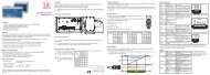
Electrical Installation7. Electrical Installation7.1 Cable ConnectionsFor the electrical installation of the <strong>thermoMETER</strong> <strong>CT</strong>, please open at first the cover of the controller(4 screws).Below the display are screw terminals for the cable connection.7.1.1 Pin Assignment7.1.1.1 <strong>CT</strong>-SF02, <strong>CT</strong>-SF15, <strong>CT</strong>-SF22, <strong>CT</strong>F-SF15, <strong>CT</strong>F-SF25, <strong>CT</strong>H-SF02, <strong>CT</strong>H-SF10, <strong>CT</strong>P ModelsPINDesignation+8 ... 36 VDC Power supplyGND Ground (0 V) of power supplyGND Ground (0 V) of internal in- and outputsOUT-A<strong>MB</strong> Analog output sensor temperature (mV)OUT-TC Analog output thermocouple (J or K)OUT-mV/mA Analog output object temperature (mV or mA)F1-F3 Functional inputsAL2Alarm 2 (Open-collector output)3V SW 3 VDC, switchable for laser sighting toolGND Ground (o V), for laser sighting toolBROWN Temperature probe sensorWHITE Temperature probe sensorGREEN Detector signal (-) Fig. 31 Opened controller <strong>CT</strong>-SF02,YELLOW Detector signal (+)<strong>CT</strong>-SF15, <strong>CT</strong>-SF22 / <strong>CT</strong>P / <strong>CT</strong>F-SF15,<strong>CT</strong>F-SF25, <strong>CT</strong>H-SF02, <strong>CT</strong>H-SF10 withterminal connections<strong>thermoMETER</strong> <strong>CT</strong>Page 43
Electrical Installation7.1.1.2 <strong>CT</strong>M-1, <strong>CT</strong>M-2, <strong>CT</strong>M-3 ModelsPINDesignation+8 ... 36 VDC Power supplyGNDGNDAL2Ground (0 V) of power supplyGround (0 V) of internal in- and outputsAlarm 2 (Open collector output)OUT-TC Analog output thermocouple (J or K)OUT-mV/mA Analog output object temperature (mV or mA)F1-F3 Functional inputsGND Ground (0 V)3V SW 3 VDC, switchable, for laser sighting toolGND Ground (0 V) for laser sighting toolBROWN BROWN/temperature probe sensor (NTC)WHITE WHITE/sensor groundGREEN GREEN/sensor power Fig. 32 Opened controllerYELLOW YELLOW/detector signal(<strong>CT</strong>M-1, <strong>CT</strong>M-2, <strong>CT</strong>M-3) with terminalconnections7.2 Power SupplyPlease use a power supply unit with an output voltage of 8 – 36 VDC/100 mA. The ripple should bemax. 200 mV.Please do never connect a supply voltage to the analog outputs.> > Destruction of the outputThe <strong>thermoMETER</strong> <strong>CT</strong> is not a 2-wire sensor!<strong>thermoMETER</strong> <strong>CT</strong>Page 44
Electrical Installation7.3 Cable AssemblingThe cable gland M12x1.5 of the controller allows the use of cables with an outer diameter of 3 to 5 mm.Remove the isolation from the cable (40 mm power supply, 50 mm signal outputs, 60 mm functionalinputs).Cut the shield down to approximately 5 mm and spread the strands out.Extract about 4 mm of the wire isolation and tin the wire ends.Place the pressing screw, the rubber washer and the metal washers of the cable gland one after theother onto the prepared cable end, see Fig. 33.Spread the strands and fix the shield between two of the metal washers.Insert the cable into the cable gland until the limit stop.Screw the cap tight.Every single wire may be connected to the appropriate screw clamps according to their colors.Metal washerRubber washerPressing screwShieldFig. 33 Cable assemblingiUse shielded cables only!The sensor shield has to be grounded!<strong>thermoMETER</strong> <strong>CT</strong>Page 45
Electrical Installation7.4 Ground ConnectionAt the bottom side of the main board PCB you will find a connector (jumper) which has been placed fromfactory side [left and middle pin connected], see Fig. 34. In this position the ground connections (GND powersupply/ outputs) are connected with the ground of the controller housing. To avoid ground loops and relatedsignal interferences in industrial environments it might be necessary to interrupt this connection.To do so, please put the jumper in the other position [middle and right pin connected].If the thermocouple output is used, the connection GND housing should generally be interrupted.Fig. 34 Connector (jumper)<strong>thermoMETER</strong> <strong>CT</strong>Page 46
Electrical Installation7.5 Exchange of the SensorFrom factory side the sensor has already been connected to the controllers and the calibration code hasbeen entered. Inside the model group <strong>CT</strong>-SF22, <strong>CT</strong>-SF15, <strong>CT</strong>-SF02, <strong>CT</strong>H-SF10, <strong>CT</strong>H-SF02 any exchange ofsensors and controllers is possible. The sensors and controllers of the models <strong>CT</strong>F-SF15 and <strong>CT</strong>F-SF25 cannotbe exchanged.7.5.1 Entering of the Calibration CodeEvery sensor has a specific calibration code, which is printed on the sensor cable. For a correct temperaturemeasurement and functionality of the sensor this calibration code must be stored into the controller. The calibrationcode consists of 3 blocks (<strong>CT</strong>M-1, <strong>CT</strong>M-2, <strong>CT</strong>M-3 = 5 blocks) with 4 characters each.Example: A6FG - 22KB - 0AS0block 1 block 2 block 3After exchanging a sensor the calibration code of the new sensor must be entered into the controller.iFig. 35 Calibration code<strong>thermoMETER</strong> <strong>CT</strong>Page 47
Electrical InstallationFor entering the code, please press the and key (keep them pressed) and then the key, seeFig. 43.The display shows HCODE and then the 4 signs of the first block. With and each sign can be changed.Please type in your specific calibration code of the sensor.You can switch to the next sign or next block with . The entering of a new calibration code can also bemade via the CompactConnect software (optional).You will find the calibration code on a label fixed on the sensor cable (near the controller, see Fig. 35).Never remove this label respectively make sure that the code is noted somewhere. The code is neededif the controller has to be exchanged or in case of a necessary recalibration of the sensor.iAfter you have modified the sensor code, a reset is necessary to activate the change, see Chap. 9.7.5.2 Sensor CableOn all <strong>CT</strong> models (exception <strong>CT</strong>M-3, <strong>CT</strong>P) the sensor cable can be shortened if necessary.On the models <strong>CT</strong>M-1, <strong>CT</strong>M-2 and <strong>CT</strong>F the sensor cable can be shortened by max. 3 m.A shortening of the cable will cause an additional measuring error of about 0.1 K/ m.The <strong>CT</strong>M-3 models are only available with 3 m cable.On the <strong>CT</strong> models <strong>CT</strong>-SF02 / <strong>CT</strong>H-SF02 / <strong>CT</strong>H-SF10 the sensor cable must not be moved during themeasurement.i<strong>thermoMETER</strong> <strong>CT</strong>Page 48
Outputs and Inputs8. Outputs and Inputs8.1 Analog OutputsThe <strong>thermoMETER</strong> <strong>CT</strong> has two analog output channels.Please do never connect a supply voltage to the analog outputs. The <strong>thermoMETER</strong> <strong>CT</strong> is not a 2-wire sensor!> > Destruction of output8.1.1 Output Channel 1This output is used for the object temperature. The selection of the output signal can be done via the programmingkeys, see Chap. 9. The CompactConnect software allows the programming of output channel 1 asan alarm output.Output signal Range Connection pin on <strong>CT</strong> boardVoltage 0 ... 5 V OUT-mV/mAVoltage 0 ... 10 V OUT-mV/mACurrent 0 ... 20 mA OUT-mV/mACurrent 4 ... 20 mA OUT-mV/mAThermo couple TC J OUT-T<strong>CT</strong>hermo couple TC K OUT-TCAccording to the chosen output signal different connection pins on the main board are used(OUT-mV/mA or OUT-TC).i8.1.2 Output Channel 2 (only <strong>CT</strong>-SF02, <strong>CT</strong>-SF15, <strong>CT</strong>-SF22, <strong>CT</strong>H, <strong>CT</strong>P)The connection pin OUT-A<strong>MB</strong> is used for output of the sensor temperature [-20 - 180 °C or -20 - 250 °C (on<strong>CT</strong>H-SF02 and <strong>CT</strong>H-SF10) as 0 - 5 V or 0 - 10 V signal]. The CompactConnect software allows the programmingof output channel 2 as an alarm output. Instead of the sensor temperature THead also the object temperatureTObj or controller temperature TBox can be selected as alarm source.<strong>thermoMETER</strong> <strong>CT</strong>Page 49
Outputs and Inputs8.2 Digital InterfacesAll <strong>CT</strong> sensors can be optionally equipped with an USB-, RS232-, RS485-, CAN Bus-, Profibus DP- or Ethernet-interface.In the case that you want to use the delivered cable gland M12x1.5 for the interface cable, please disassemblethe terminal block and assemble them again.To install, first remove the housing cover to get access to the interior of the housing.Now take the particular interface board and insert it into the slot provided in the controller.The slot is located on the left side of the display, see Fig. 36.In the correct position the holes of the interface match with the thread holes of the controller.Now press the interface board down gently to connect it and use both M3x5 screws for fixing it in thecontroller housing.Plug the pre-assembled interface cable with the terminal block into the male connector of the interfaceboard.Fig. 36 Interface boardiPleaseExchange the blind screw on the controller by the cable gland of the respective interface and install theappropriate interface cable.also pay attention to the additional notes for installing the respective interfaces, see Chap. 8.2.1,see Chap. 8.2.2 and the following interface chapters.<strong>thermoMETER</strong> <strong>CT</strong>Page 50
Outputs and Inputs8.2.1 USB Interface8.2.1.1 InstallationMount the USB adapter, see Chap. 8.2.iMake sure the wiring is correct according to the wire colors printed on the interface board.For industrial installations it is recommended to connect the shield of the USB adapter cable with the controllerhousing (inside the cable gland).The <strong>CT</strong> does not need external power supply for operation – it will be powered by the USB interface.If an external power supply has already been installed, this will not affect the functionality of the <strong>CT</strong>.8.2.1.2 Driver Installation of InterfacePlease install the CompactConnect software, see Chap. 11.Now please press the button Install Adapter driver.All necessary device drivers will be installed. After connecting new sensors or new USB adapter cables toyour PC the system will automatically allocate them to the correct driver. If the Found New Hardware Wizardappears you can select Connect to Windows Update or Install the Software automatically.After you have connected the USB-cable to your PC and started the CompactConnect software the communicationwill be established. If the recognition is not automatic, you will find the drivers on the CompactConnect Software CD in the path \Driver \ Infrared Sensor Adapter.<strong>thermoMETER</strong> <strong>CT</strong>Page 51
Outputs and Inputs8.2.2 RS232 Interface8.2.2.1 InstallationMount the RS232 adapter, see Chap. 8.2.iMake sure the wiring is correct according to the drawing and designation printed on the interface board,see Fig. 37.The <strong>CT</strong> always needs an external power supply for operation.8.2.2.2 Software InstallationPlease install the CompactConnect software, see Chap. 11.Follow the software instruction manual on the delivered CompactConnect software CD.After you have connected the RS232 cable to your PC and started the CompactConnect software the communicationwill be established.The setting for baud rate in the CompactConnect software must be the same as on the <strong>thermoMETER</strong> <strong>CT</strong> unit(factory default: 9.6 kBaud).Please make sure that the option Scan non-USB devices in menu Preferences/Options is activatedin the CompactConnect software.iGND - brownTXD - greenRXD - whiteFig. 37 Pin assignment RS232<strong>thermoMETER</strong> <strong>CT</strong>Page 52
Outputs and Inputs8.2.3 RS485 Interface8.2.3.1 InstallationMount the RS485 adapter, see Chap. 8.2.The RS485-USB adapter is providing a 2-wire half-duplex mode.Please connect terminal A of the interface with terminal A of the next RS485 interface and so on, see Fig.38. With the B terminal proceed as well.iMake sure that you always connect A to A and B to B, not reverse.You may run up to 32 <strong>CT</strong> units on one RS485-USB adapter.Turn the 120R-switch to ON only at one of the connected <strong>CT</strong> units.120R switch OFFMultidrop address 1120R switch OFFMultidrop address n120R switch ONMultidrop address 32Fig. 38 Pin assignment RS485<strong>thermoMETER</strong> <strong>CT</strong>Page 53
Outputs and Inputs8.2.3.2 Sensor InstallationEach <strong>CT</strong> unit connected to the RS485 needs a different multidrop address (1 ... 32).Please adjust the address by pressing thebutton until M xx appears in the display.Using the Up and Down keys you can change the shown address (xx) The address can also be changedwith the CompactConnect software. The baud rate setting in the CompactConnect software must be thesame as on the <strong>CT</strong> unit (factory default: 9.6 kBaud.)Please install the CompactConnect software, see Chap. 11.Please connect the RS485 USB adapter (TM-RS485USBK-<strong>CT</strong>) via the supplied USB cable with your PC.After it has been connected the computer will recognize a new USB device and (if connected the first time)will ask for installation of the according driver software.Please select Search and install the RS485 adapter USB driver from the CompactConnect software CD.<strong>thermoMETER</strong> <strong>CT</strong>Page 54
Outputs and Inputs8.2.4 Profibus Interface8.2.4.1 InstallationMount the Profibus adapter, see Chap. 8.2.iMake sure the wiring is correct, see Fig. 39.iWe recommend for industrial installations to connect the shield of the Profibus cable with the controllerhousing (inside the cable gland).The <strong>thermoMETER</strong> <strong>CT</strong> always needs an external power supply.Connector Color Function PinA Green A 2B Red B 4GND Blue Ground 33541VCC Brown +5 V (not used) 1Shield n.c. 52HousingSilver (shield)Fig. 39 Pin assignment Profibus interfaceM12 round connectorView on solder pinside 5-pin. roundconnector<strong>thermoMETER</strong> <strong>CT</strong>Page 55
Outputs and Inputs8.2.4.2 Commissioning ProfibusRead in the „IT010A90.gsd“ GSD file, contained on the delivered CompactConnect software CD, into thePLC configuration tool and configure the controller.At least one module must be selected. You will find more information about the Profibus interface on theenclosed CompactConnect software CD, page 18.Open the controller and connect the power supply, see Fig. 40.ConnectionProfibus cablePower supplySensor cableGND+8 up to +36 VDCFig. 40 Commissioning Profibus<strong>thermoMETER</strong> <strong>CT</strong>Switch on the power supply.Press the Mode button 18 times until the item „SL001“ appears. Set the slave address with the UP andDOWN buttons. Valid slave addresses start with 001 up to 125. Use the same address as in the PLC configurationtool, see the Profibus instruction manual on page 4, 6 on CompactConnect Software CD.Switch off the controller for at least 3 seconds by interrupting the power supply.Connect the connector of the Profibus cable with a Profibus port. Take care on the terminating resistor ofthe Profibus.The controller with DPv1 Profibus is now ready for data exchange with the Profibus master; see the Profibusinstruction manual on page 7 on CompactConnect Software CD.The measuring values are displayed in hex format and must be converted into decimals; see the Profibusinstruction manual on page 7 on CompactConnect Software CD.The settings of the DPv1 Profibus interface and the communication with the Profibus master are described inthe Profibus instruction manual on CompactConnect Software CD.Page 56
Outputs and Inputs8.2.5 CAN BUS InterfaceMount the CAN BUS adapter, see Chap. 8.2.iMake sure the wiring is correct, see Fig. 39.iWe recommend for industrial installations to connect the shield of the CAN BUS cable with the controllerhousing (inside the cable gland).The <strong>thermoMETER</strong> <strong>CT</strong> always needs an external power supply.CAN ProtocolCAN open (see documentation on CompactConnect software CD)WiringCAN Bus:CAN_H on terminal „H“CAN_L on terminal „L“Analog signal:Black cord on terminal „GND“Red cord on terminal „OUT-mV“The controller contains additional terminals to connect other devices (power supply, CAN bus, terminatingresistor).<strong>thermoMETER</strong> <strong>CT</strong>Page 57
Outputs and InputsCAN module factory settingsModule address: 20 (14 H)Baud rate: 250 kBaudAnalog input: 0 … 10 VTemperature range: 0 … 60 °C (2 decimal places)Emission ratio: 0.970The settings for “Analog output 0 … 10 V“ and “Temperature range 0 … 60 °C” on the <strong>CT</strong> sensor mustbe identical with the CAN bus module values.iFactory settings address and baud rateCAN open service „LSS / Layer Setting Services“Index temperature value:The temperature information is located in the object register 7130h (Sub01):e.g.B4: LBB4: DAB5: HBB5: 07 T = 20.10 °CBefore delivery, MICRO-EPSILON can set parameters, desired by the customer, for an extra charge. For thesubsequent conversion a CAN master is required.DiagnosisIf the power supply is on, the LED displays one of the following conditions:StateFlashes quicklyOffIlluminatesSparklesMeaningDevice is in preoperational mode.Power supply is not correct / faulty hardware.Device is in operational mode.Device is stopped. = Communication stopped.<strong>thermoMETER</strong> <strong>CT</strong>Page 58
Outputs and Inputs8.2.6 Ethernet Interface8.2.6.1 InstallationMount the Ethernet adapter, see Chap. 8.2.In case you want to run the pre-mounted cable of the Ethernet box through the delivered cable gland,the terminal block has to be disassembled/assembled.The <strong>thermoMETER</strong> <strong>CT</strong> always requires an external power supply of at least 12 V.iMake sure the wiring is correct according to the colors printed on the interface board.Please connect the shield of the cable with the controller housing (inside the cable gland).Please connect the Ethernet adapter device with your network using an Ethernet cable.<strong>thermoMETER</strong> <strong>CT</strong>Page 59
Outputs and Inputs8.2.6.2 Installation of the Ethernet Adapter in a NetworkFirst connect the PC to the Internet.Please install the CompactConnect software CD, see Chap. 11.If the autorun option is activated the installation wizard will start automatically. Otherwise please start CDsetup.exefrom the CompactConnect software CD. The following screen will appear, see Fig. 41.Fig. 41 View CompactConnect CD-ROMNow install the device driver by selecting Install Ethernet Driver.<strong>thermoMETER</strong> <strong>CT</strong>Page 60
Outputs and InputsSelect Add New Device and press Weiter.The IP and MAC address of the Ethernet adapter willappear in the list. You will find the MAC address alsoprinted on the Ethernet adapter.Please mark the adapter in the list and pressWeiter.<strong>thermoMETER</strong> <strong>CT</strong>Page 61
Outputs and InputsThe following screen shows all settings.Please press Fertig stellen.The device will be installed inside the network.<strong>thermoMETER</strong> <strong>CT</strong>Page 62
Outputs and Inputs8.2.6.3 Uninstalling the Ethernet Adapter in a NetworkTo deinstall an adapter please follow the steps describedunder Network Installation, see Chap. 8.2.6.2.Select Remove an Existing Device andpress then Weiter.In the upper overview all on the PC installed Ethernetadapter are shown.Select the adapter(s) which should be deinstalledand press Weiter.<strong>thermoMETER</strong> <strong>CT</strong>Page 63
Outputs and Inputs8.2.6.4 Direct Connection to a PCIf a direct connection between Ethernet adapter and PC is required both have to be connected via a crossovercable. In addition the adapter and the PC need to get a fixed IP address.Please open the Windows device manager after the network installation (Start/Control panel/System/Hardware/Device manager).Please choose Mehrfachadapter/Multiadapter (serial) from the list.By double clicking the desired Ethernet adapter, aproperties window is opening.Please open the tab Advanced in this window.Beside Device UI you will find a linkwith the network IP address.<strong>thermoMETER</strong> <strong>CT</strong>Page 64
Outputs and InputsBy clicking on the link the configuration page for the Ethernet adapter will be opened in your web browser.Please select Network (Navigation left; below configuration).<strong>thermoMETER</strong> <strong>CT</strong>Page 65
Outputs and InputsIn the input mask Use the following IP address below you can now enter a fixed IP address.Confirm your settings with Apply.<strong>thermoMETER</strong> <strong>CT</strong>Page 66
Outputs and InputsFor a communication with the adapter you now have to configure the network settings on your PC.Please open the LAN settings (Start/Control panel/Network settings/Settings).Mark the LAN connection and open the properties window using the right mouse button.<strong>thermoMETER</strong> <strong>CT</strong>Page 67
Outputs and InputsDouble click on Internetprotokoll/Internetprotocol (TCP/IP).iPlease enter here a fixed IP address for thePC.Please note that the first three blocks (example:192.168.049) have to match with theIP address of the adapter device.Press OK.The installation is finished.<strong>thermoMETER</strong> <strong>CT</strong>Page 68
Outputs and Inputs8.2.6.5 Settings inside the CompactConnect SoftwareAfter a successful network installation of the Ethernetadapter you can start the CompactConnectsoftware.To make sure that an available device can be foundyou should first activate the function Scan non-USB devices in the menu point Preferences/Options:Furthermore you should set the Communicationmode to Standard (menu: Measurement/Settings).This activates the so called polling mode 1 (bidirectionalcommunication).1) Polling Mode = Method, to determine the status of a device consisting of hardware or software or theevent of a change of values by cyclic queries.<strong>thermoMETER</strong> <strong>CT</strong>Page 69
Outputs and Inputs8.2.6.7 Resetting the Ethernet AdapterThe Ethernet adapter can be reset to the factory setting.iPlease use a ballpoint pen to press the reset button (hole at the top of the housing).Switch on the power supply while pressing the reset button.After a few seconds you will see a flashing green LED (network connection).Please wait until the green LED flashes with a 1-5-1 1 pattern, then you can release the reset button.Wait until the adapter boots again.The configuration is reset to factory setting during this time.The configuration is not reset, if you switch off the adapter before you release the reset button.The adapter will show an undefined configuration 2 , if you switch off the adapter briefly after you have releasedthe reset button.The adapter works in the DHCP mode after resetting.If you want to make a direct connection to a PC, see Chap. 8.2.6.4.1) Flashing - break - 5 x flashing - break - flashing2) If necessary only some values are reset.<strong>thermoMETER</strong> <strong>CT</strong>Page 70
Outputs and Inputs8.3 Relays OutputsThe <strong>thermoMETER</strong> <strong>CT</strong> can optionally be equipped with a relay output. The relay board is installed the sameway as the digital interfaces, see Chap. 8.2.Connect the external electrical circuit with the terminal blocks.A simultaneous installation of a digital interface and the relay outputs is not possible.The switching thresholds correspondent with the values for alarm 1 and 2, see Chap. 8.5, see Chap. 8.5.2.and are factory-set, see Chap. A 1:Alarm 1 = 30 °C/ norm. Closed (Low-Alarm) and Alarm 2 = 100 °C/ norm. open (High-Alarm).The adjustment of the alarms can result from the modification of the alarm 1 and alarm 2 via the programmingkeys.To make advanced settings (change of low- and high alarm) a digital interface (USB, RS232) and the CompactConnectsoftware is needed.Fig. 42 Relay interface with pin assignment<strong>thermoMETER</strong> <strong>CT</strong>Page 71
Outputs and Inputs8.4 Functional InputsThe three functional inputs F1 - F3 can be programmed with the CompactConnect software, only.F1 (digital)Trigger (a 0 V - level on F1 resets the hold functions)F2 (analog) External emissivity adjustment [0 - 10 V: 0 V e = 0.1; 9 V e = 1; 10 V e = 1.1]F3 (analog)F1 - F3 (digital)External compensation of ambient temperature/the range is scalable via CompactConnectsoftware[0 - 10 V: -40 - 900 °C/preset range: -20 - 200 °C]Emissivity (digital choice via table)A non-connected input represents:F1 = HighF2, F3 = LowHigh-level: ≥ +3 V ... +36 VLow-level: ≤ +0.4 V ... -36 V<strong>thermoMETER</strong> <strong>CT</strong>Page 72
Outputs and Inputs8.5 AlarmsThe <strong>thermoMETER</strong> <strong>CT</strong> has following alarm features:All alarms (alarm 1, alarm 2, output channel 1 and 2 if used as alarm output) have a fixed hysteresis of 2 K<strong>CT</strong>H: 1 K).8.5.1 Output Channel 1 and 2 (Channel 2 on <strong>CT</strong>-SF / <strong>CT</strong>P)The respective output channel has to be switched into digital mode for activation. For this the CompactConnectsoftware is required.8.5.2 Visual AlarmsThese alarms will cause a change of color of the LCD display and will also change the status of the optionalrelays interface. In addition, Alarm 2 can be used as open collector output at pin AL2 on the controller [24 V/50 mA].The alarms are factory-set as follows:Alarm 1 Norm. closed/Low-AlarmAlarm 2 Norm. open/High-AlarmBoth of these alarms will have effect on the LCD color:BLUE Alarm 1 activeRED Alarm 2 activeGREEN No alarm activeFor extended setup like definition as low or high alarm (via change of normally open/closed), selection ofthe signal source (TObj, THead, TBox) a digital interface (e.g. USB, RS232) including the CompactConnectsoftware is needed.<strong>thermoMETER</strong> <strong>CT</strong>Page 73
Operating9. OperatingAfter powering up the supply voltage the sensor starts an initializing routine for some seconds. During thistime the display will show INIT. After this procedure the object temperature is shown in the display. Thedisplay backlight color changes according to the alarm settings, see Chap. 8.5, see Chap. 8.5.2.9.1 Restoring Factory SettingTo set the <strong>thermoMETER</strong> <strong>CT</strong> back to the factory settings, please first press the and then the buttonand keep both pressed for approximately 3 seconds.The display will show RESET for confirmation.Display Modes [Sample] Adjustment Range142.3C Object temperature (after signal processing)[142.3 °C]Fixed127CH Sensor temperature [127 °C] Fixed25CB Box temperature Fixed142CA Current object temperature FixedMV5 Signal output channel 1 [0 - 5 V] 0 - 20 = 0 - 20 mA/4 - 20 = 4 - 20 mA/MV5 = 0 - 5 V/MV10 = 0 - 10 V/TCJ = Thermocouple type J/TCK = Thermocouple type KE0.970 Emissivity [0.970] 0.100 ... 1.100T1.000 Transmissivity [1.000] 0.100 ... 1.100A 0.2 Signal Output Average [0.2 s] A---- = inactive/ 0.1 ... 999.9 s<strong>thermoMETER</strong> <strong>CT</strong>Page 74
OperatingDisplay Mode [Sample] Adjustment rangeP---- Signal output peak hold [inactive] P---- = inactive/0.1 ... 999.9 s/P ∞ ∞ ∞ ∞ =infiniteV---- Signal output valley hold [inactive] V---- = inactive/0.1 ... 999.9 s /V ∞ ∞ ∞ ∞ =infiniteu 0.0 Lower limit temperature range [0 °C] Depending on model/inactive at TCJ and TCKoutputn 500.0 Upper limit temperature range [500 °C] Depending on model/ inactive at TCJ- and TCKoutput[ 0.00 Lower limit signal output [0 V] According to the range of the selected output] 5.00 Upper limit signal output [5 V] According to the range of the selected outputU °C Temperature unit [°C] °C/°F/ 30.0 Lower alarm limit [30 °C] Depending on model// 100.0 Upper alarm limit [100 °C] Depending on modelXHEADAmbient temperature compensation[Sensor temperature]M 01 Multidrop address [1](only with RS485 interface)XHEAD = sensor temperature/-40.0 ... 900.0 °C(for <strong>CT</strong>-SF) as fixed value for compensation/returning to XHEAD (sensor temperature) bypressing and together01 ... 32B 9.6 Baud rate in kBaud [9.6] 9.6/19.2/38.4/57.6/115.2 kBaudS ON Laser eyepiece (3 VDC-switches to the connectionON/OFF; This menu item appears on the modelspin „3 VSW“)<strong>CT</strong>M-1, <strong>CT</strong>M-2, <strong>CT</strong>M-3 on firstposition.<strong>thermoMETER</strong> <strong>CT</strong>Page 75
Operating9.2 Sensor SetupThe programming keys , and enable the user to set the sensor on-site. The current measuringvalue or the chosen feature is displayed. With the operator obtains the chosen feature, with andthe functional parameters can be selected – a change of parameters will have immediate effect. If no key ispressed for more than 10 seconds the display automatically shows the calculated object temperature (accordingto the signal processing).Mode Up DownFig. 43 Display and programming keysPressing the button again recalls the last called function on the display. The signal processing featurespeak hold and valley hold cannot be selected simultaneously.<strong>thermoMETER</strong> <strong>CT</strong>Page 76
Operating9.3 Explanation to the Menu ItemsDisplayDescriptionMV5 Selection of the output signal. By pressing or the different output signals can be selected,see Chap. 9.1EO.970 Setup of emissivity. Pressing increases the value; decreases the value (also valid for allfurther functions). The emissivity (e - <strong>Epsilon</strong>) is a material constant factor to describe the abilityof the body to emit infrared energy, see Chap. 14.T1.000 Setup of transmissivity. This function is used if an optical component (protective window, additionaloptics e.g.) is mounted between sensor and object. The standard setting is 1.000 =100 % (if no protective window etc. is used).A 0.2P----V----Setup of average time. In this mode an arithmetic algorithm will be performed to smoothenthe signal. The set time is the time constant. This function can be combined with all other postprocessing functions. On <strong>CT</strong>M-1, <strong>CT</strong>M-2, <strong>CT</strong>M-3 models the shortest value is 0.001 s (othermodels: 0.1 s) and can be only increased/decreased by values of the power series of 2 (0.002,0.004, 0.008, 0.016, 0.032, ...). If the value is set to 0.0 the display will show --- (function deactivated).Setup of peak hold. In this mode the sensor is waiting for descending signals. If the signaldescends the algorithm maintains the previous signal peak for the specified time. After the holdtime the signal will drop down to the second highest value or will descend by 1/8 of the differencebetween the previous peak and the minimum value during the hold time. This value willbe held again for the specified time. After this the signal will drop down with slow time constantand will follow the current object temperature.If the value is set to 0.0 the display will show --- (function deactivated).Setup of valley hold. In this mode the sensor waits for ascending signals. The definition of thealgorithm is equal to the peak hold algorithm (inverted). If the value is set to 0.0 the display willshow --- (function deactivated).<strong>thermoMETER</strong> <strong>CT</strong>Page 77
OperatingFig. 44 Signal graphs with P---Red graph TProcess with peak hold (hold time = 1 s)Blue graph TActual without post processingDisplayu 0.0n 500.0DescriptionSetup of the lower limit of temperature range. The minimum difference between lower and upperlimit is 20 K. If you set the lower limit to a value ≥ upper limit, the upper limit will be adjustedto [lower limit + 20 K] automatically.Setup of the upper limit of the temperature range. The minimum difference between upper andlower limit is 20 K. The upper limit can only be set to a value = lower limit +20 K.[ 0.00 Setup of the lower limit of the signal output. This setting allows an assignment of a certain signaloutput level to the lower limit of the temperature range. The adjustment range correspondsto the selected output mode (e.g. 0 - 5 V).<strong>thermoMETER</strong> <strong>CT</strong>Page 78
OperatingDisplayDescription] 5.00 Setup of the upper limit of the signal output. This setting allows an assignment of a certain signaloutput level to the lower limit of the temperature range. The adjustment range correspondsto the selected output mode (e.g. 0 - 5 V).U °C Setup of the temperature unit [°C or °F]/ 30.0 Setup of the lower alarm limit. This value corresponds to alarm 1, see Chap. 8.5, see Chap.8.5.2, and is also used as threshold value for relay 1 (if the optional relay board is used).// 100.0 Setup of the upper alarm limit. This value corresponds to alarm 2, see Chap. 8.5, see Chap.8.5.2, and is also used as threshold value for relay 2 (if the optional relay board is used).XHEADM 01B 9.6S ONSetup of the ambient temperature compensation. In dependence on the emissivity value ofthe object a certain amount of ambient radiation will be reflected from the object surface. Tocompensate for this impact, this function allows the setup of a fixed value which represents theambient radiation.Especially if there is a big difference between the ambient temperature at the object andthe sensor temperature the use of ambient temperature compensation is recommended.iIf XHEAD is shown the ambient temperature value will be taken from the sensor-internal probe.To return to XHEAD, please press and together.Setup of the Multidrop address. In a RS485 network each sensor will need a specific address.This menu item will only be shown if a RS485 interface board is plugged in.Setup of the baud rate for digital data transferActivating (ON) and Deactivating (OFF) of an optional sighting laser, see Chap. 6.3. By pressingor a voltage of 3 VDC will be switched to the 3V SW connection pin on the controller.<strong>thermoMETER</strong> <strong>CT</strong>Page 79
Operating9.4 Error MessagesThe display of the <strong>thermoMETER</strong> <strong>CT</strong> can show the following error messages:9.4.1 <strong>CT</strong>-SF02, <strong>CT</strong>-SF15, <strong>CT</strong>-SF22, <strong>CT</strong>H and <strong>CT</strong>P ModelsOVER Object temperature too highUNDER Object temperature too low^^^CH Sensor temperature to highvvvCH Sensor temperature to low9.4.2 <strong>CT</strong>M-1, <strong>CT</strong>M-2, <strong>CT</strong>M-3 Models1. Digit0x No error1x Sensor temperture probe short circuit GND2x Box temperature too low4x Box temperature too high6x Box temperature probe disconnected8x Box temperature probe short circuit to GND2. Digitx0x2x4x8xCNo errorObject temperature too highSensor temperature too lowSensor temperature too highSensor temperature probe disconnected<strong>thermoMETER</strong> <strong>CT</strong>Page 80
Instructions for Operation10. Instructions for Operation10.1 CleaningLens cleaning: Blow off loose particles using clean compressed air. The lens surface can be cleaned with asoft, humid tissue moistened with water or a water based glass cleaner.Never use cleaning compounds which contain solvents (neither for the lens nor for the housing).> > Destruction of the sensor and/or the controller<strong>thermoMETER</strong> <strong>CT</strong>Page 81
CompactConnect Software11. CompactConnect SoftwareInsert the CompactConnect installation CD into the according drive on your computer.If the auto run option is activated the installation wizard will start automatically.Otherwise, please start CDsetup.exe from the CD-ROM.Follow the instructions of the wizard until the installation is finished.The installation wizard will place a launch icon on the desktop and in the start menu.If you want to uninstall the CompactConnect software from your system, please use the uninstall icon inthe start menu.You will find detailed software manual on the CompactConnect CD.11.1 System Requirements--Windows XP, Windows Vista, Windows 7 and 8--At least 128 <strong>MB</strong>yte RAM--USB Interface--CD-ROM drive--Hard disc with at least 30 <strong>MB</strong>yte free space11.2 Main Features--Graphical display for temperature measuring values andautomatic data logging for analysis and documentation--Complete sensor setup and remote controlling--Adjustment of signal processing functions--Programming of outputs and functional inputsFig. 45 Graphic display main features<strong>thermoMETER</strong> <strong>CT</strong>Page 82
Communication Settings12. Communication Settings12.1 Serial InterfaceBaud rate:Data bits: 8Parity:noneStop bits: 1Flow control: off12.2 Protocol9.6 ... 115.2 kBaud (adjustable on the unit or via CompactConnect software)All sensors of the <strong>CT</strong> series are using a binary protocol. They can be switched alternatively to an ASCII protocol.To get a fast communication the protocol has no additional overhead with CR, LR or ACK bytes.12.3 ASCII ProtocolThe models <strong>CT</strong>-SF02, <strong>CT</strong>-SF15, <strong>CT</strong>-SF22, <strong>CT</strong>H-SF02, <strong>CT</strong>H-SF10 can be switched to ASCII by changing thefirst figure of block 3 of the sensor calibration code. This figure has to be changed from 0 to 4 (always +4;that means on the <strong>CT</strong>ex this figure has to be changed from 1 to 5), see Chap. 7.5.Example: Binary: A6FG - 22KB - 0AS0 ASCII: A6FG - 22KB - 4AS0Block 1 Block 2 Block 3 Block 1 Block 2 Block 3After you have modified the sensor calibration code a reset is necessary to activate the change, seeChap. 9.iTo switch to the ASCII protocol you can also use the following command:Decimal: 131HEX:0x83Data, answer: byte 1Result: 0 – Binary protocol1 – ASCII protocol<strong>thermoMETER</strong> <strong>CT</strong>Page 83
Communication Settings12.4 Saving of Parameter SettingsAfter switching on the <strong>CT</strong> sensor, the flash mode is active. This means that changed parameter settings willbe saved in the <strong>CT</strong>-internal Flash-EEPROM and will also be kept after the sensor is switched off.In case values should be changed quite often or continuously the flash mode can be switched off by usingthe following command:Decimal: 112HEX:0x70Data, answer: byte 1Result:0 – Data will be written into the flash memory1 – Data will be not written into the flash memoryIf the flash mode is deactivated, all settings will only be kept as long as the unit is powered. If the unit isswitched off and powered on again, all previous settings are lost.The command 0x71 will poll the current status.You will find a detailed protocol and command description on the CompactConnect software CD in the directory:\Commands.<strong>thermoMETER</strong> <strong>CT</strong>Page 84
Basics of Infrared Thermometry13. Basics of Infrared ThermometryDepending on the temperature each object emits a certain amount of infrared radiation. A change in thetemperature of the object is accompanied by a change in the intensity of the radiation. For the measurementof “thermal radiation” infrared thermometry uses a wave-length ranging between 1 μ and 20 μm. The intensityof the emitted radiation depends on the material. This material contingent constant is described with the helpof the emissivity (e - <strong>Epsilon</strong>) which is a known value for most materials, see Chap. A 2, see Chap. A 3.Infrared thermometers are optoelectronic sensors. They calculate the surface temperature on the basis of theemitted infrared radiation from an object. The most important feature of infrared thermometers is that they enablethe user to measure objects contactless. Consequently, these products help to measure the temperatureof inaccessible or moving objects without difficulties. Infrared thermometers basically consist of the followingcomponents:--Lens--Spectral filter--Detector--Controller (Amplifier/linearization/signal processing)The specifications of the lens decisively determine the optical path of the infrared thermometer, which is characterizedby the ratio Distance to Spot size.The spectral filter selects the wavelength range, which is relevant for the temperature measurement. Theemitted infrared radiation is transformed into electrical signals by the detector and the controller.<strong>thermoMETER</strong> <strong>CT</strong>Page 85
Emissivity14. Emissivity<strong>thermoMETER</strong> <strong>CT</strong>14.1 DefinitionThe intensity of infrared radiation, which is emitted by each body, depends on the temperature as well as onthe radiation features of the surface material of the measuring object. The emissivity (e – <strong>Epsilon</strong>) is used asa material constant factor to describe the ability of the body to emit infrared energy. It can range between 0and 100 %. A “blackbody” is the ideal radiation source with an emissivity of 1.0 whereas a mirror shows anemissivity of 0.1.If the emissivity chosen is too high, the infrared thermometer may display a temperature value which is muchlower than the real temperature – assuming the measuring object is warmer than its surroundings. A lowemissivity (reflective surfaces) carries the risk of inaccurate measuring results by interfering infrared radiationemitted by background objects (flames, heating systems, chamottes). To minimize measuring errors in suchcases, the handling should be performed very carefully and the unit should be protected against reflectingradiation sources.14.2 Determination of Unknown Emissivity--First of all, determine the current temperature of the measuring object with a thermocouple or contact sensor.The second step is to measure the temperature with the infrared thermometer and modify the emissivityuntil the displayed measuring value corresponds to the current temperature.--If you monitor temperatures of up to 380 °C you may place a special plastic sticker (Part number: TM-ED-<strong>CT</strong> emissivity dots) onto the measuring object, which covers it completely.Now set the emissivity to 0.95 and take the temperature of the sticker.Afterwards, determine the temperature of the adjacent area on the measuring object and adjust theemissivity according to the value of the temperature of the sticker.--Cover a part of the surface of the measuring object with a black, flat paint with an emissivity of 0.98.Adjust the emissivity of your infrared thermometer to 0.98 and take the temperature of the colored surface.Afterwards, determine the temperature of a directly adjacent area and modify the emissivity until themeasured value corresponds to the temperature of the colored surface.iOn all three methods the object temperature must be different from the ambient temperature.Page 86
Emissivity14.3 Characteristic EmissivityIn the case that none of the methods mentioned above help to determine the emissivity you may use theemissivity tables, see Chap. A 2, see Chap. A 3. These are only average values. The actual emissivity of a materialdepends on the following factors:--Temperature--Measuring angle--Geometry of the surface (smooth, convex, concave)--Thickness of the material--Constitution of the surface (polished, oxidized, rough, sandblast)--Spectral range of the measurement--Transmissivity (e.g. with thin films)<strong>thermoMETER</strong> <strong>CT</strong>Page 87
Warranty15. WarrantyAll components of the device have been checked and tested for perfect function in the factory. In the unlikelyevent that errors should occur despite our thorough quality control, this should be reported immediately toMICRO-EPSILON.The warranty period lasts 12 months following the day of shipment. Defective parts, except wear parts, will berepaired or replaced free of charge within this period if you return the device free of cost to MICRO-EPSILON.This warranty does not apply to damage resulting from abuse of the equipment and devices, from forcefulhandling or installation of the devices or from repair or modifications performed by third parties.No other claims, except as warranted, are accepted. The terms of the purchasing contract apply in full.MICRO-EPSILON will specifically not be responsible for eventual consequential damages. MICRO-EPSILONalways strives to supply the customers with the finest and most advanced equipment. Development and refinementis therefore performed continuously and the right to design changes without prior notice is accordinglyreserved.For translations in other languages, the data and statements in the German language operation manual areto be taken as authoritative.<strong>thermoMETER</strong> <strong>CT</strong>Page 88
16. Service, RepairIn the event of a defect on the sensor, controller orthe sensor cable please send us the affected partsfor repair or exchange.In the case of faults the cause of which is notclearly identifiable, the entire measuring systemmust be sent back to:For customers in USA applies:Send the affected parts or the entire measuringsystem back to:For customers in Canada or South America applies:Please contact your local distributor.MICRO-EPSILON MESSTECHNIKGmbH & Co. KGKönigbacher Str. 1594496 Ortenburg / GermanyTel. +49 (0) 8542/ 168-0Fax +49 (0) 8542 / 168-90info@micro-epsilon.dewww.micro-epsilon.comMICRO-EPSILON USA8120 Brownleigh Dr.Raleigh, NC 27617 /USATel. +1 919 / 787-9707Fax +1 919 / 787-9706me-usa@micro-epsilon.comwww.micro-epsilon.com17. Decommissioning, DisposalDisconnect the sensor and controller cables.The <strong>thermoMETER</strong> <strong>CT</strong> is produced according to the directive 2011/65/EU “RoHS“,Do the disposal according to the legal regulations (see directive 2002/96/EC).<strong>thermoMETER</strong> <strong>CT</strong>Seite 89
Appendix | Factory SettingsAppendixA 1Factory SettingsThe devices have following presettings at time of delivery:Signal output object temperatureEmissivity0 - 5 VTransmissivity 1.0000.970 (<strong>CT</strong>, <strong>CT</strong>P)/1.000 (<strong>CT</strong>M-1, <strong>CT</strong>M-2, <strong>CT</strong>M-3)Averaging (AVG) 0.2 s (<strong>CT</strong>F: 0.1 s)/(<strong>CT</strong>M-1, <strong>CT</strong>M-2, <strong>CT</strong>M-3: 0.001 s)Smart AveragingPeak hold (MAX)Valley hold (MIN)Lower limit signal outputUpper limit signal outputinactive/(<strong>CT</strong>F, <strong>CT</strong>M-1, <strong>CT</strong>M-2, <strong>CT</strong>M-3: active)inactiveinactive0 V5 VTemperature unit °CAmbient temperature compensation 1Baud rate [kBaud] 1151) Output at OUT-A<strong>MB</strong> as 0 - 5 V signal on <strong>CT</strong>-SF and <strong>CT</strong>PModelinternal sensor temperature probe<strong>CT</strong>-SF02/15/22/<strong>CT</strong>F/<strong>CT</strong>H<strong>CT</strong>M-1SF40 <strong>CT</strong>M-1SF75 <strong>CT</strong>M-1SF75H1<strong>CT</strong>M-2SF40<strong>CT</strong>M-2SF75Lower limit temperature range [°C] 0 485 650 800 250 385Upper limit temperature range [°C] 500 1050 1800 2200 800 1600Lower alarm limit [°C]30 600 800 1200 350 500(normally closed)Upper alarm limit [°C](normally open)100 900 1400 1600 600 1200<strong>thermoMETER</strong> <strong>CT</strong>Seite 90
Appendix | Factory SettingsModel <strong>CT</strong>M-2SF75H1 <strong>CT</strong>M-3SF22 <strong>CT</strong>M-3SF33 <strong>CT</strong>M-3SF75H1Lower limit temperature range [°C] 490 50 100 150Upper limit temperature range [°C] 2000 400 600 1000Lower alarm limit [°C]800 100 250 350(normally closed)Upper alarm limit [°C](normally open)1400 300 500 600Model <strong>CT</strong>M-3SF75H2 <strong>CT</strong>M-3SF75H3 <strong>CT</strong>PLower limit temperature range [°C] 200 250 0Upper limit temperature range [°C] 1500 1800 710Lower alarm limit [°C]550 750 30(normally closed)Upper alarm limit [°C]1000 1200 100(normally open)Smart Averaging means a dynamic average adaptation at high signal edges (activation via CompactConnectsoftware only), see Chap. A 4.<strong>thermoMETER</strong> <strong>CT</strong>Seite 91
Appendix | Emissivity Table MetalsA 2iEmissivity Table MetalsPlease note that these are only approximate values, which were taken from various sources.MaterialTypical EmissivitySpectral response 1.0 μm 1.6 μm 5.1 μm 8 - 14 μmAluminum Non oxidized 0.1 - 0.2 0.02 - 0.2 0.02 - 0.2 0.02 - 0.1Polished 0.1 - 0.2 0.02 - 0.1 0.02 - 0.1 0.02 - 0.1Roughened 0.2 - 0.8 0.2 - 0.6 0.1 - 0.4 0.1 - 0.3Oxidized 0.4 0.4 0.2 - 0.4 0.2 - 0.4Brass Polished 0.35 0.01 - 0.05 0.01 - 0.05 0.01 - 0.05Roughened 0.65 0.4 0.3 0.3Oxidized 0.6 0.6 0.5 0.5Copper Polished 0.05 0.03 0.03 0.03Roughened 0.05 - 0.2 0.05 - 0.2 0.05 - 0.15 0.05 - 0.1Oxidized 0.2 - 0.8 0.2 - 0.9 0.5 - 0.8 0.4 - 0.8Chrome 0.4 0.4 0.03 - 0.3 0.02 - 0.2Gold 0.3 0.01 - 0.1 0.01 - 0.1 0.01 - 0.1Haynes Alloy 0.5 - 0.9 0.6 - 0.9 0.3 - 0.8 0.3 - 0.8InconelElectropolished0.2 - 0.5 0.25 0.15 0.15Sandblast 0.3 - 0.4 0.3 - 0.6 0.3 - 0.6 0.3 - 0.6Oxidized 0.4 - 0.9 0.6 - 0.9 0.6 - 0.9 0.7 - 0.95<strong>thermoMETER</strong> <strong>CT</strong>Seite 92
Appendix | Factory SettingsMaterialTypical EmissivitySpectral response 1.0 μm 1.6 μm 5.1 μm 8 - 14 μmIron Non oxidized 0.35 0.1 - 0.3 0.05 - 0.25 0.05 - 0.2Rusted 0.6 - 0.9 0.5 - 0.8 0.5 - 0.7Oxidized 0.7 - 0.9 0.5 - 0.9 0.6 - 0.9 0.5 - 0.9Forget, blunt 0.9 0.9 0.9 0.9Molten 0.35 0.4 - 0.6Iron, casted Non oxidized 0.35 0.3 0.25 0.2Oxidized 0.9 0.7 - 0.9 0.65 - 0.95 0.6 - 0.95Lead Polished 0.35 0.05 - 0.2 0.05 - 0.2 0.05 - 0.1Roughened 0.65 0.6 0.4 0.4Oxidized 0.3 - 0.7 0.2 - 0.7 0.2 - 0.6Magnesium 0.3 - 0.8 0.05 - 0.3 0.03 - 0.15 0.02 - 0.1Mercury 0.05 - 0.15 0.05 - 0.15 0.05 - 0.15Molybdenum Non oxidized 0.25 - 0.35 0.1 - 0.3 0.1 - 0.15 0.1Oxidized 0.5 - 0.9 0.4 - 0.9 0.3 - 0.7 0.2 - 0.6Monel (Ni-CU) 0.3 0.2 - 0.6 0.1 - 0.5 0.1 - 0.14Nickel Electrolytic 0.2 - 0.4 0.1 - 0.3 0.1 - 0.15 0.05 - 0.15Oxidized 0.8 - 0.9 0.4 - 0.7 0.3 - 0.6 0.2 - 0.5Platinum Black 0.95 0.9 0.9Silver 0.04 0.02 0.02 0.02<strong>thermoMETER</strong> <strong>CT</strong>Seite 93
Appendix | Emissivity Table Non MetalsMaterialTypical EmissivitySpectral response 1.0 μm 1.6 μm 5.1 μm 8 - 14 μmSteel Polished plate 0.35 0.25 0.1 0.1Rustless 0.35 0.2 - 0.9 0.15 - 0.8 0.1 - 0.8Heavy plate 0.5 - 0.7 0.4 - 0.6Cold-rolled 0.8 - 0.9 0.8 - 0.9 0.8 - 0.9 0.7 - 0.9Oxidized 0.8 - 0.9 0.9 - 0.9 0.7 -0.9 0.7 - 0.9Tin Non oxidized 0.25 0.1 - 0.3 0.05 0.05Titanium Polished 0.5 - 0.75 0.3 - 0.5 0.1 - 0.3 0.05 - 0.2Oxidized 0.6 - 0.8 0.5 - 0.7 0.5 - 0.6Wolfram Polished 0.35 - 0.4 0.1 - 0.3 0.05 - 0.25 0.03 - 0.1Zinc Polished 0.5 0.05 0.03 0.02Oxidized 0.6 0.15 0.1 0.1<strong>thermoMETER</strong> <strong>CT</strong>Seite 94
Appendix | Emissivity Table Non MetalsA 3 Emissivity Table Non MetalsPlease note that these are only approximate values which were taken from various sources.iMaterialTypical EmissivitySpectral response 1.0 μm 2.2 μm 5.1 μm 8 - 14 μmAsbest 0.9 0.8 0.9 0.95Aphalt 0.95 0.95Basalt 0.7 0.7Carbon Non oxidized 0.8 - 0.9 0.8 - 0.9 0.8 - 0.9Graphite 0.8 - 0.9 0.7 - 0.9 0.7 - 0.9Carborundum 0.4 0.8 - 0.95 0.8 - 0.95 0.95Cement 0.65 0.9 0.9 0.95Glass Plate 0.2 0.98 0.85Melt 0.4 - 0.9 0.9Grit 0.95 0.95Gypsum 0.4 - 0.97 0.8 - 0.95Ice 0.98Limestone 0.4 - 0.98 0.98Paint Non alcaline 0.9 - 0.95Paper Any color 0.95 0.95Plastic > 50 μm Non transparent 0.95 0.95Rubber 0.9 0.95Sand 0.9 0.95<strong>thermoMETER</strong> <strong>CT</strong>Seite 95
Appendix | Smart AveragingMaterialTypical EmissivitySpectral response 1.0 μm 2.2 μm 5.1 μm 8 - 14 μmSnow 0.9Soil 0.9 - 0.98Textiles 0.95 0.95Water 0.93Wood Natural 0.9 - 0.95 0.9 - 0.95<strong>thermoMETER</strong> <strong>CT</strong>Seite 96
Appendix | Smart AveragingA 4Smart AveragingThe average function is generally used to smoothen the signal curves. With the adjustable parameter time thisfunction can be optimal adjusted to the respective application. One disadvantage of the average function is thatfast temperature peaks which are caused by dynamic events are subjected to the same averaging time. Thereforethose peaks can only be seen with a delay on the signal output.The function Smart Averaging eliminates this disadvantage by passing those fast events without averaging directlythrough to the signal output.Fig. 46 Signal curve with Smart Averaging functionFig. 47 Signal curve without Smart Averaging function<strong>thermoMETER</strong> <strong>CT</strong>Seite 97
MICRO-EPSILON MESSTECHNIK GmbH & Co. KGKönigbacher Str. 15 · 94496 Ortenburg / GermanyTel. +49 (0) 8542 / 168-0 · Fax +49 (0) 8542 / 168-90info@micro-epsilon.de · www.micro-epsilon.comX9751190-B041104HDRMICRO-EPSILON MESSTECHNIK*X9751190-B04*