DMS1000-V1_4-00- Prospekt - Martens Elektronik GmbH
DMS1000-V1_4-00- Prospekt - Martens Elektronik GmbH
DMS1000-V1_4-00- Prospekt - Martens Elektronik GmbH
- No tags were found...

Create successful ePaper yourself
Turn your PDF publications into a flip-book with our unique Google optimized e-Paper software.
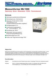
Strain-Bridge Converter DMS 1<strong>00</strong>0Weight - Force - Pressure - Torque with DMS Strain-BridgesFeaturesM 1- or 2 way action, e.g. force orforce/traction programmableM Teach-in functionM Front side LCD-Display with backlightingM Programming via front keypadM Tare-function (internal / external) and simulation modeM Integrated bridge-supply 2.5 V/5 V/10 VM Resolution 16 BitM Accuracy
Technical dataPower supplySupply voltage : 230 V AC ±10 %; 115 V AC ±10 %; 24 V AC ±10 % or 24 V DC ±15 %Power consumption : max. 3.5 VAWorking temperature : -10 ... +55 °C (14 ... 131 °F)Rated voltage: 250 V~ acc. to DIN VDE 0110 between, input, analog output/relay output/supply voltage,Degree of pollution 2, over-voltage category IIITest voltage: 4kV=, between input, analog output/relay output/supply voltage- conformity : EN55022, EN60555, IEC61<strong>00</strong>0-4-3/4/5/11/13InputBridge supplyBridge sensitivitySense connectionAccuracyTemperature coefficientDisplayDisplay rangeOutputRelayAnalog output-AccuracyCaseDimensionsWeightConnectionProtection: 2.5/5/10 V DC ; programmable; max. 50 mA: 0.4/0.2/0.1 ... 5.<strong>00</strong> mV/V: Line resistance about max. 10 Ω is compensated: < 0.05 % ±2 Digit: 0.<strong>00</strong>5 %/K: LCD Dot-Matrix 2 lines 8 characters each, character height 5 mm, backlighting: ±9999(0) digit with leading zero suppression: SPDT
Connection diagramsStrain-bridge Booster SBB 16160/24 V DCModel 20/24 V DCModel 2Model 1Model 1Supply +Signal +ShieldSignal -SenseSupply -TareTareSupply +Signal +ShieldSignal -SenseSupply -TareTareAnalog output0/4 ... 20 mA0 ... 10 V DCAlarm outputSupply voltageAnalog output0/4 ... 20 mA0 ... 10 V DCAlarm outputSupply voltageControls and indicatorsProcess valueAlarm output (active)Field for additionaltextParameter buttonDown buttonUp buttonDescriptionOperation of the device is arranged in 2 levels. While programming, pressing button saves the current parameterand moves to the next programming step. For selection within a parameter or for entering data, usebuttons and .Button combinations:+ one parameter back.+ setting parameter to zero or minimum value.After powering up, the device initializes itself. The display shows the message <strong>DMS1<strong>00</strong>0</strong> and software version.After the initialization the device is located in the Working level. The set point of the alarm output can be adjustedand min- and max. values can be called.Pressing the button for more than 2 seconds, activates the Configuration level. Now all the parameterswhich defines the function of the converter can be programmed.After finishing the configuration or when no button was pushed for more than 2 minutes, the program returns tothe working level and the display shows the process value. Leaving the configuration level is possible at anytime by pushing the button for 2 seconds.Error messages:Display flashes If the input signal leaves the programmed range.P-ERRORFactory calibration is necessaryP-lock Programming lock. See configuration page 7, parameter 23Installation note!Before the device can be used, it must be configured for the intended use. ⇒ see page 5- 3 -
Notes to representationParameter is only displayed if configuredParameter is only displayed if included (see order code)Note:All parameters can be called if they are not blocked by other programmed parameters and if they areavailable. Factory settings are shown in the display graphic.Working levelButton Display DescriptionALO450kgProcess-valueIndication of alarm output (only if activated).□ = OFF and ■ = ONmax558kgDisplay max. valueReset with button, or at every power off.min-1kgDisplay min. valueReset with button, or at every power off.Tare1kgTare-functionPressing button for more than 3 s ,the display will be reset to “ 0 ".DsplConvX1.<strong>00</strong>Display conversion, option 11Setting possible from x0,10 ... x10,<strong>00</strong>with buttons und .Alarmp.10Setpoint alarm outputSetting possible in the programmed measuring rangewith buttons und .- 4 -
ConfigurationButton Display Description (displayed values are factory settings)press2s1O deutschG englishConfiguration levelLanguage of the operating instructionsSelection with buttons and .2D.-Filt.0.1sDigital filter.Averaging of the measured values over the programmed time [s].OFF, 0.1, 1.5, 10, 20, 40sSelection with buttons and .3UnitDis– kgDisplay unitkg, t, N, kN, barSelection with buttons and .4FixedOAUS GANFixed zero 0, e.g. 25<strong>00</strong>+0.Selection with buttons and .5DecPoint– <strong>00</strong><strong>00</strong>Decimal point position<strong>00</strong><strong>00</strong>; <strong>00</strong>0,0; <strong>00</strong>,<strong>00</strong>; 0,<strong>00</strong>0Selection with buttons and .6UnitCell– kgMeasuring unit of the strain bridge (load cell)kg, t, N, kN, barSelection with button and .7Nom. kg1<strong>00</strong>0Nominal load of the strain bridge (load cell)Setting possible from 1 ... 9999 Digit with buttons and .If the load is distributed to several identic cells, the summation of the nominalload has to be entered.8Supply–Ub=2.5VBridge supply2.5V, 5V , 10V DCSelection with buttons and .continuepage 6- 5 -
Button Display Description (displayed values are factory settings)9TeachIn?OOFF GONTeach-in function.Adjustment of the strain-bridge with reference weights to determine thebridge-sensitivity [mV/V].Selection with buttons and .10m1 kg01. calibration pointSetting possible in range of the programmed nominal loadwith buttons and .This parameter will not be left automatically after 120 seconds.11m2kg1802. calibration pointThe difference to the 1.calibration point must be at least 10% of the programmednominal load.Setting possible with buttons and .This parameter will not be left automatically after 120 seconds.12DMS mV/V2.<strong>00</strong>0Bridge-sensitivity [mV/V]Setting possible from 0.1<strong>00</strong> ... 5.<strong>00</strong>0mV/Vwith buttons and .If the load is distributed to several identic cells, the arithmetic average valueof the bridge sensitivity has to be entered.Note: When the teach-in function is accomplished, the calculated value ofthe sensitivity will be displayed. If this value is out of range, an error messageoccurs and the value will not be stored.13Direct– 1-dirDirection of action.1-dir = 0 ... measuring range; or 2-dir = 0 ... ± measuring range.Selection with buttons and .14Output– 0-20mAAnalog output0 - 20, 4 - 20 mA or 0-10VSelection with buttons and .15MR Start0kgStart value for measuring range and analog outputSetting possible from 0 (-9999) ... 9999 digitwith buttons and .continuepage 716MR End1<strong>00</strong>0kgEnd value for measuring range and analog outputSetting possible from -9999 ... 9999 digitwith buttons and .Note:If MR Start > MR End, the output works with a decreasing characteristic- 6 -
Button Display Description (displayed values are factory settings)17Alarm–OFFSwitching performance alarm outputOFF, MIN, MAXSelection with buttons and .18Setpoint0Setpoint alarm outputSetting possible within the programmed measuring rangewith buttons and .19Hyst.1Hysteresis alarm outputSetting possible within the programmed measuring rangewith buttons and .20Simul.1850kg21Corr.AO0.<strong>00</strong>0mASimulation of the load-cellThe <strong>DMS1<strong>00</strong>0</strong> works as a simulator. The analog output changes within theprogrammed measuring range.Setting possible with the buttons and .Please note: This parameter will not be left automatically after 120 seconds.Correction start value analog outputSetting possible ±2 mA or ±1 V with buttons and .22Corr.AO20.<strong>00</strong>0mACorrection end value analog outputSetting possible ±2 mA or ±1 V with buttons and .23P-Lock– OFF24Parameter lockOFF: no lockoutCONFIG : configuration level lockedALL: all parameters lockedSelection with buttons and .Code for factory settingsFactCode0ALO450kgBack to the working level- 7 -
Ordering code<strong>DMS1<strong>00</strong>0</strong> -1.-2.-3.-4.-5.-6.1. Model12Input Strain-Bridge (DMS-load cell),integrated bridge-supply 2.5/5/10 V DC max. 50 mA,input for extern tare function with voltage free contactas before, but extern tare function with 24 V DC signalintern isolated by opto-coupler2. Alarm output1R 1 Alarm output3. Analog outputAO Analog outputRelay SPDT0/4 ... 20 mA or 0/2 ... 10 V DCnot isolated to the measuring input4. Supply voltage0 230 V AC1 115 V AC4 24 V AC5 24 V DC± 10 %± 10 %± 10 %± 15 %50-60 Hz50-60 Hz50-60 Hz5. Option<strong>00</strong>11Without optionDisplay conversion from x0,10 ... x10,<strong>00</strong>6. Additional text (appears on the face plate in the field additional text,maximum 3mm x 50mm wxH )- 8 -10/05-<strong>V1</strong>.4-<strong>00</strong>