EO18-12003 - toshiba tec europe
EO18-12003 - toshiba tec europe EO18-12003 - toshiba tec europe
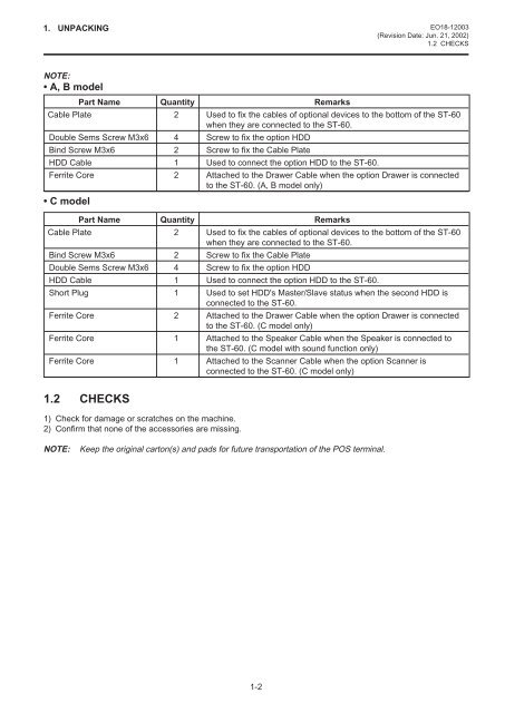
1. UNPACKING EO18-12003(Revision Date: Jun. 21, 2002)1.2 CHECKSNOTE:• A, B modelPart Name Quantity RemarksCable Plate 2 Used to fix the cables of optional devices to the bottom of the ST-60when they are connected to the ST-60.Double Sems Screw M3x6 4 Screw to fix the option HDDBind Screw M3x6 2 Screw to fix the Cable PlateHDD Cable 1 Used to connect the option HDD to the ST-60.Ferrite Core 2 Attached to the Drawer Cable when the option Drawer is connectedto the ST-60. (A, B model only)• C modelPart Name Quantity RemarksCable Plate 2 Used to fix the cables of optional devices to the bottom of the ST-60when they are connected to the ST-60.Bind Screw M3x6 2 Screw to fix the Cable PlateDouble Sems Screw M3x6 4 Screw to fix the option HDDHDD Cable 1 Used to connect the option HDD to the ST-60.Short Plug 1 Used to set HDD's Master/Slave status when the second HDD isconnected to the ST-60.Ferrite Core 2 Attached to the Drawer Cable when the option Drawer is connectedto the ST-60. (C model only)Ferrite Core 1 Attached to the Speaker Cable when the Speaker is connected tothe ST-60. (C model with sound function only)Ferrite Core 1 Attached to the Scanner Cable when the option Scanner isconnected to the ST-60. (C model only)1.2 CHECKS1) Check for damage or scratches on the machine.2) Confirm that none of the accessories are missing.NOTE:Keep the original carton(s) and pads for future transportation of the POS terminal.1-2
2. BEFORE INSTALLATION EO18-120032.1 ENVIRONMENT FOR INSTALLATION2. BEFORE INSTALLATION2.1 ENVIRONMENT FOR INSTALLATIONSince heat will be built up inside the unit during operation, ventilating slits are provided to vent the internal air.When installing the terminal, be sure to allow a 30mm or more clearance on both sides of the terminal so as notto block the ventilating slits.2.2 ARRANGING CABLES OF EACH MODULEOn the bottom of the ST-60 terminal, fix each cable of module to the cable clamp located at the center of theterminal, and lead the cables into one of the three cable outlets. After that, fix them with the provided cableclamp and the B-3x6 screw.Cable Clamp2-1
- Page 1 and 2: TEC POS TerminalST-60 SERIESMainten
- Page 3 and 4: TABLE OF CONTENTSEO18-12003(Revisio
- Page 5: 1. UNPACKING EO18-12003(Revision Da
- Page 9 and 10: 3. MAIN UNIT REPLACEMENT EO18-12003
- Page 11 and 12: 3. MAIN UNIT REPLACEMENT EO18-12003
- Page 13 and 14: 3. MAIN UNIT REPLACEMENT EO18-12003
- Page 15 and 16: 3. MAIN UNIT REPLACEMENT EO18-12003
- Page 17 and 18: 3. MAIN UNIT REPLACEMENT EO18-12003
- Page 19 and 20: 3. MAIN UNIT REPLACEMENT EO18-12003
- Page 21 and 22: 3. MAIN UNIT REPLACEMENT EO18-12003
- Page 23 and 24: 3. MAIN UNIT REPLACEMENT EO18-12003
- Page 25 and 26: 3. MAIN UNIT REPLACEMENT EO18-12003
- Page 27 and 28: 4. INSTALLATION PROCEDURE FOR OPTIO
- Page 29 and 30: 4. INSTALLATION PROCEDURE FOR OPTIO
- Page 31 and 32: 4. INSTALLATION PROCEDURE FOR OPTIO
- Page 33 and 34: 4. INSTALLATION PROCEDURE FOR OPTIO
- Page 35 and 36: 4. INSTALLATION PROCEDURE FOR OPTIO
- Page 37 and 38: 4. INSTALLATION PROCEDURE FOR OPTIO
- Page 39 and 40: 4. INSTALLATION PROCEDURE FOR OPTIO
- Page 41 and 42: 4. INSTALLATION PROCEDURE FOR OPTIO
- Page 43 and 44: 5. ST-60 BIOS SETUP (A, B models) E
- Page 45 and 46: 5. ST-60 BIOS SETUP (A, B models) E
- Page 47 and 48: 5. ST-60 BIOS SETUP (A, B models) E
- Page 49 and 50: 5. ST-60 BIOS SETUP (A, B models) E
- Page 51 and 52: 5. ST-60 BIOS SETUP (A, B models) E
- Page 53 and 54: 5. ST-60 BIOS SETUP (A, B models) E
- Page 55 and 56: 5. ST-60 BIOS SETUP (A, B models) E
1. UNPACKING <strong>EO18</strong>-<strong>12003</strong>(Revision Date: Jun. 21, 2002)1.2 CHECKSNOTE:• A, B modelPart Name Quantity RemarksCable Plate 2 Used to fix the cables of optional devices to the bottom of the ST-60when they are connected to the ST-60.Double Sems Screw M3x6 4 Screw to fix the option HDDBind Screw M3x6 2 Screw to fix the Cable PlateHDD Cable 1 Used to connect the option HDD to the ST-60.Ferrite Core 2 Attached to the Drawer Cable when the option Drawer is connectedto the ST-60. (A, B model only)• C modelPart Name Quantity RemarksCable Plate 2 Used to fix the cables of optional devices to the bottom of the ST-60when they are connected to the ST-60.Bind Screw M3x6 2 Screw to fix the Cable PlateDouble Sems Screw M3x6 4 Screw to fix the option HDDHDD Cable 1 Used to connect the option HDD to the ST-60.Short Plug 1 Used to set HDD's Master/Slave status when the second HDD isconnected to the ST-60.Ferrite Core 2 Attached to the Drawer Cable when the option Drawer is connectedto the ST-60. (C model only)Ferrite Core 1 Attached to the Speaker Cable when the Speaker is connected tothe ST-60. (C model with sound function only)Ferrite Core 1 Attached to the Scanner Cable when the option Scanner isconnected to the ST-60. (C model only)1.2 CHECKS1) Check for damage or scratches on the machine.2) Confirm that none of the accessories are missing.NOTE:Keep the original carton(s) and pads for future transportation of the POS terminal.1-2


