

EO18-12003 - toshiba tec europe
EO18-12003 - toshiba tec europe
EO18-12003 - toshiba tec europe
- No tags were found...

You also want an ePaper? Increase the reach of your titles
YUMPU automatically turns print PDFs into web optimized ePapers that Google loves.
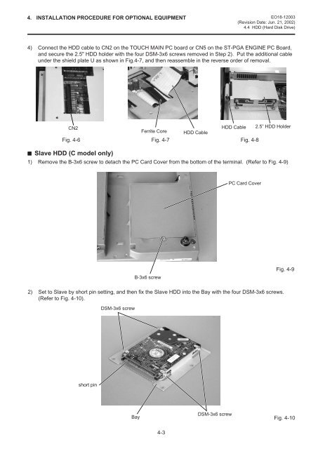
4. INSTALLATION PROCEDURE FOR OPTIONAL EQUIPMENT <strong>EO18</strong>-<strong>12003</strong>(Revision Date: Jun. 21, 2002)4.4 HDD (Hard Disk Drive)4) Connect the HDD cable to CN2 on the TOUCH MAIN PC board or CN5 on the ST-PGA ENGINE PC Board,and secure the 2.5" HDD holder with the four DSM-3x6 screws removed in Step 2). Put the additional cableunder the shield plate U as shown in Fig.4-7, and then reassemble in the reverse order of removal.CN2HDD Cable 2.5” HDD HolderFerrite Core HDD CableFig. 4-6 Fig. 4-7 Fig. 4-8Slave HDD (C model only)1) Remove the B-3x6 screw to detach the PC Card Cover from the bottom of the terminal. (Refer to Fig. 4-9)PC Card CoverB-3x6 screwFig. 4-92) Set to Slave by short pin setting, and then fix the Slave HDD into the Bay with the four DSM-3x6 screws.(Refer to Fig. 4-10).DSM-3x6 screwshort pinBayDSM-3x6 screwFig. 4-104-3


