

EO18-12003 - toshiba tec europe
EO18-12003 - toshiba tec europe
EO18-12003 - toshiba tec europe
- No tags were found...

You also want an ePaper? Increase the reach of your titles
YUMPU automatically turns print PDFs into web optimized ePapers that Google loves.
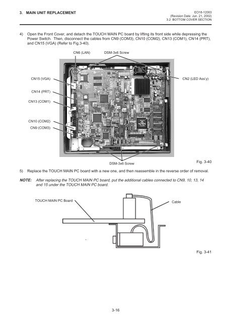
3. MAIN UNIT REPLACEMENT <strong>EO18</strong>-<strong>12003</strong>(Revision Date: Jun. 21, 2002)3.2 BOTTOM COVER SECTION4) Open the Front Cover, and detach the TOUCH MAIN PC board by lifting its front side while depressing thePower Switch. Then, disconnect the cables from CN9 (COM3), CN10 (COM2), CN13 (COM1), CN14 (PRT),and CN15 (VGA) (Refer to Fig.3-40).CN6 (LAN)DSM-3x6 ScrewCN15 (VGA)CN2 (LED Ass’y)CN14 (PRT)CN13 (COM1)CN10 (COM2)CN9 (COM3)DSM-3x6 ScrewFig. 3-405) Replace the TOUCH MAIN PC board with a new one, and then reassemble in the reverse order of removal.NOTE: After replacing the TOUCH MAIN PC board, put the additional cables connected to CN9, 10, 13, 14and 15 under the TOUCH MAIN PC board.TOUCH MAIN PC BoardCableFig. 3-413-16


