Sepam series 20 Sepam series 40 - Schneider Electric
Sepam series 20 Sepam series 40 - Schneider Electric
Sepam series 20 Sepam series 40 - Schneider Electric
- No tags were found...
You also want an ePaper? Increase the reach of your titles
YUMPU automatically turns print PDFs into web optimized ePapers that Google loves.
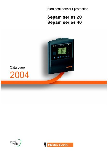
<strong>Electric</strong>al network protection<strong>Sepam</strong> <strong>series</strong> <strong>20</strong><strong>Sepam</strong> <strong>series</strong> <strong>40</strong>Catalogue<strong>20</strong>04
ContentsPresentation 2More solutions 2Flexible architecture 5User-machine interface 6Selection table 8<strong>Sepam</strong> <strong>series</strong> <strong>20</strong> 8<strong>Sepam</strong> <strong>series</strong> <strong>40</strong> 9Metering 10Description 10General settings and characteristics 11Protection 12Description 12Setting ranges 15Connection diagrams 18<strong>Sepam</strong> <strong>series</strong> <strong>20</strong> 18<strong>Sepam</strong> <strong>series</strong> <strong>40</strong> 19Phase current inputs <strong>20</strong>Residual current input 21<strong>Sepam</strong> <strong>series</strong> <strong>20</strong> voltage inputs 22<strong>Sepam</strong> <strong>series</strong> <strong>40</strong> voltage inputs 23Control and monitoring 24Description 24Logic inputs and outputs 25Logic input / output assignment for <strong>Sepam</strong> <strong>series</strong> <strong>20</strong> 26Logic input / output assignment for <strong>Sepam</strong> <strong>series</strong> <strong>40</strong> 27Annunciation 28Customization 29Communication 30Description and characteristics 30Optional remote modules 32Description 32Connections 33Sensors 34LPCT type current sensors 34Core balance CTs 35Characteristics 36Size and weight 36<strong>Electric</strong>al characteristics 38Environmental characteristics 39Order form 41Breakdown of base units into basic references 41Order form 421
PresentationMore solutionsMT11017MT11017The <strong>Sepam</strong> <strong>series</strong> <strong>20</strong> and <strong>Sepam</strong> <strong>series</strong><strong>40</strong> families of protection and metering unitsare designed for the operation of machinesand electrical distribution networks ofindustrial installations and utility substationsfor all levels of voltage.They consist of complete, simple andreliable solutions, suited to the followingapplications:b protection of substations (incomers andfeeders)b protection of transformersb protection of motorsb protection of generatorsb protection of busbars.<strong>Sepam</strong> <strong>series</strong> <strong>20</strong>Suitable for common applications, <strong>Sepam</strong> <strong>series</strong> <strong>20</strong> offers simple solutionsbased on current or voltage metering.b protection of substation incomers and feeders against phase-to-phase andphase-to-earth short-circuitsv 16 IDMT tripping curvesv adjustable timer hold to detect recurrent faultsv switching of groups of settings to adapt to changes in the network configurationb protection of overhead lines with built-in recloser functionb protection of transformers against overloads, with ambient temperaturecompensatedRMS thermal overload protection with 2 groups of settings for differentventilation operating ratesb protection of motorsv against overloads, with ambient temperature-compensated RMS thermal overloadprotection with a cold tripping curve that can be adjusted to fit motor characteristicsv against internal faults and load-related faultsv with motor starting condition monitoring and machine operation assistance.The <strong>Sepam</strong> <strong>series</strong> <strong>20</strong> B21 and B22 voltage units are suitable for the followingsituations:b monitoring of network voltage and frequencyb loss of mains detection by rate of change of frequency protection for installationswith local power generation.<strong>Sepam</strong> <strong>series</strong> <strong>40</strong><strong>Sepam</strong> <strong>series</strong> <strong>40</strong>, with its current and voltage metering capabilities, offers highperformingsolutions for more demanding applications.<strong>Sepam</strong> <strong>series</strong> <strong>40</strong> units perform the following funcitons in addition to those performedby <strong>Sepam</strong> <strong>series</strong> <strong>20</strong>:b protection of closed ring networks or networks with parallel incomers, bydirectional protectionb directional earth fault protection suitable for all earthing systems: impedant,isolated or compensated neutralb protection of networks with variable configurations requiring the switching ofgroups of settings and logic discriminationb all the necessary electrical measurements: phase and residual currents, phase-toneutral,phase-to-phase and residual voltage, frequency, power and energy, ...b comprehensive network diagnosis assistance: <strong>20</strong> seconds of disturbancerecording, detailed history of the last <strong>20</strong>0 alarms, storage of the last 5 trippingcontextsb adaptation of control functions by a logical equation editorb customization of alarm messages to fit each application, and/or in the user’slanguage.<strong>Sepam</strong> selection guideSelection Series <strong>20</strong> Series <strong>40</strong>criteriaMeasurements I U U I and U I and U I and USpecificprotectionfunctionsavailableApplicationsTypeLoss ofmains(ROCOF)Directionalearth faultDirectionalearth fault andphaseovercurrentSubstation S<strong>20</strong> S<strong>40</strong> S41 S42Transformer T<strong>20</strong> T<strong>40</strong> T42Motor M<strong>20</strong> M41GeneratorG<strong>40</strong>Busbar B21 B22Example: For motor protection and current and voltage measurements, your solutionis the M41 type <strong>Sepam</strong>.2
PresentationMore solutionsPE50239PE502<strong>40</strong>Example: Advanced UMI customized for Chinese users.More simplicitySimple to installb no constraints for integration in cubicles due to the compact size of the base unitsand remote installation of optional modulesb universal auxiliary power supply.Simple to commissionb all the functions are ready to useb user-friendly, powerful PC setting software to utilize all the possibilities offered by<strong>Sepam</strong>.Simple to operateWith the advanced UMI, all local operations are made easier by a clear, completepresentation of all the required information in your language.Simple to maintainb digital unit self-diagnosis and watchdogb switchgear diagnosis assistance functions to assess equipment condition andschedule preventive maintenance operations:v cumulative breaking currentv breaking device operating and charging time.Example: Standard advanced UMI in English.MT11019PE50027PE50028Supervision of an electrical network equipped with <strong>Sepam</strong> bymeans of PowerLogic System SMS software.More communicationModbus communicationAll the data needed for centralized management of your electrical network areavailable with the communication option based on the open, international Modbusprotocol:b measurement and diagnosis valuesb remote indication and time-tagging of eventsb remote control of the installationb remote setting of protection functionsb reading of disturbance recording files.Ethernet connection and Webserver<strong>Sepam</strong> may be connected to an Ethernet high speed network by means of aModbus-RS 485/Modbus - Ethernet TCP/IP communication interface.This interface allows:b integration of <strong>Sepam</strong> in a multi-master architecture on Ethernet networksb consultation of Web pages of data transmitted by <strong>Sepam</strong> via an Internet/Intranetbrowser.Other protocols<strong>Sepam</strong> may be connected to communication network based on protocols other thanModbus by using a gateway / protocol converter.In particular, a Modbus / DNP3 converter has been qualified for the connection of<strong>Sepam</strong> to DNP3 network.Please consult us for more informations.PowerLogic System<strong>Sepam</strong> fits naturally into PowerLogic System power management systems.EGX<strong>20</strong>0 Ethernet gateway.3
PresentationMore solutionsMore modularity<strong>Sepam</strong> <strong>series</strong> <strong>20</strong> and <strong>Sepam</strong> <strong>series</strong> <strong>40</strong> are available with 2 User-MachineInterface (UMI) levels:b advanced UMI, with keypad and graphic LCD displayv to provide all the data required for local operation of the installation:measurements, diagnosis information, alarms, etc.v to set <strong>Sepam</strong> parameters and protection functionsv to be understood by all, the screens can be displayed in the user’s language.The advanced UMI may be part of the base unit or installed as a remote unit in themost convenient location for the user.b basic UMI, with signal lampsv for remotely operated installations, via the communication link, with no continuousneed for local operation; a PC equipped with the SFT2841 software tool may be usedfor occasional operation.In order to adapt to as many situations as possible and allow for subsequentupgrading of the installation, <strong>Sepam</strong> may be functionally enhanced at any timeby the addition of optional modules.b logic input/output module with parameterizable program logicb communication moduleb temperature sensor moduleb analog output module.PE50241PE50242<strong>Sepam</strong> with basic UMI.<strong>Sepam</strong> with advanced UMI.PE50243<strong>Sepam</strong> with remote advanced UMI.4
PresentationFlexible architecturePE502441 Base unit, with different User-Machine Interface (UMI) levels:b basic UMIb advanced UMI with fixed or remote graphic LCD display.2 Logic inputs/outputs module.3 Modbus communication network connection module.4 Low level analog output module.5 Temperature sensor acquisition module for transformer, motor orgenerator.6 Software tools:b <strong>Sepam</strong> parameter and protection setting and program logic customizationb display of disturbance recording files.5
PresentationUser-machine interfaceMT10122<strong>Sepam</strong> has 2 levels of UMI (user-machineinterface) suited to every operatingrequirement.onI>51I >> 51Io > 51NIo >> 51Next0 off I on TripresetBasic UMIThis UMI offers an economical solution suited to installations that do not require localoperation (managed by a remote monitoring and control system)or to replace electromechanical or analog electronic protections units with noadditional operating needs.The basic UMI includes:b 2 signal lamps indicating <strong>Sepam</strong> operating status:v green "on" indicator: device onv red "wrench" indicator: device unavailable (initialization phase or detection of aninternal failure)b 9 parameterizable yellow signal lamps equipped with a standard label (1)b "reset" button for clearing faults and resettingb 1 connection port for the RS 232 link with the PC; the port is protected by a slidingcover.DE50595Basic UMI with standard signal lamp assignment.on9I>51I> > 518Io > 51N7Io >> 51NAdvanced UMI with standard signal lamp assignment.extI1 = 162A RMSI2 = 161A RMSI3 = 163A RMS6clear50 offI onreset4trip123Advanced UMIThis UMI is an optimal solution for local operation, which is made easier by itslegibility, content and access to the different data.In addition to the basic UMI functions, this version provides:b a "graphic" LCD display with automatic contrast adjustment and user-triggeredbacklighting. It is used to display measurements, parameter/protection settings andalarm and operating messages.Number of lines, size of characters and symbols according to screens and languageversions.b a 9-key keypad with two operating modes:White keys for current operation:1 display of measurements.2 display of switchgear and network diagnosis data.3 display of alarm messages.4 resetting.5 acknowledgment and clearing of alarms.Blue keys for parameter and protection setting:789access to protection settings.access to <strong>Sepam</strong> parameter settings (2) .used to enter the 2 passwords required to change protection and parametersettings.The " ↵, r, " keys ( 4 , 5 , 6 ) are used to navigate in the menus, and to scrolland accept the values displayed."Lamp test" key 6 :switching-on sequence of all the signal lamps.rRemote advanced UMIThe advanced UMI functions are also available in a remote module that is connectedto a <strong>Sepam</strong> with a basic UMI (connection by prefabricated cord of different lengths).The module is installed on the front panel of the cubicle in the most appropriateoperating location.(1) This removable label may be replaced by a customized label produced using the SFT2841software tool.(2) For parameter setting of the program logic, the expert UMI must be used.6
PresentationUser-machine interfaceMT11102MT11103SFT2841: measurement screen.SFT2841: protection function 50/51 setting screen.Expert UMIThis UMI is available as a complement to the basic or advanced UMI on the screenof a PC equipped with the SFT2841 software tool and connected to the RS 232 linkon the front panel of the <strong>Sepam</strong> (operating in a Windows environment).All the data used for the same task are grouped together in the same screen tofacilitate operation. Menus and icons are used for fast, direct access to the requiredinformation.Current operating modeThis UMI is the solution suited to occasional local operation for demanding personnelwho require fast access to all the information.b display of all metering and operating datab display of alarm messages with the time of appearanceb display of diagnosis data such as:v tripping currentv number of switchgear operations and cumulative breaking currentb display of all protection and parameter settings madeb display of the logic status of inputs, outputs and signal lamps.Parameter / protection setting modeUsed for the display and setting of all the parameters; input data may be preparedahead of time and transferred into the corresponding <strong>Sepam</strong> units in a singleoperation (downloading function).Main functions performed by SFT2841:b changing of passwordsb entry of general settings (ratings, integration period, …) protected by a parametersetting passwordb entry of protection settings in the same page, protected by a setting passwordb modification of program logic assignmentsb enabling/disabling of functionsb saving of files.Saving - printing of reportsb protection and parameter setting data may be savedb reports may also be printed, by exporting the data into a text file.This UMI may also be used to recover disturbance recording files and display themusing the SFT2826 software tool.Operating assistanceAccess from all the screens to a help section which contains all the technical datarequired for <strong>Sepam</strong> installation and use.SFT2841 kitThe expert UMI software tool comes in a kit which contains:b 1 CD-ROM with:v SFT2841 softwarev SFT2826 software for disturbance recording file displayb 1 PC/<strong>Sepam</strong> serial link cord.Minimum configuration requiredProcessorPC compatible, Pentium 133 MHzOperating systemsMicrosoft Windows 98/NT4.0/<strong>20</strong>00/XPRAM 64 MB (32 MB for Windows 98)Space on disk64 MB7
Selection table <strong>Sepam</strong> <strong>series</strong> <strong>20</strong>FunctionsType of <strong>Sepam</strong>Substation Transformer Motor BusbarProtection ANSI code S<strong>20</strong> T<strong>20</strong> M<strong>20</strong> B21 (3) B22Phase overcurrent 50/51 4 4 4Earth fault,sensitive earth fault50N/51N50G/51G4 4 4Negative sequence / unbalance 46 1 1 1Thermal overload 49RMS 2 2Phase undercurrent 37 1Locked rotor, excessive starting time 48/51LR/14 1Starts per hour 66 1Positive sequence undervoltage 27D/47 2 2Remanent undervoltage 27R 1 1Phase-to-phase undervoltage 27 2 2Phase-to-neutral undervoltage 27S 1 1Phase-to-phase overvoltage 59 2 2Neutral voltage displacement 59N 2 2Overfrequency 81H 1 1Underfrequency 81L 2 2Rate of change of frequency 81R 1Recloser (4 cycles) 79 vThermostat / Buchholz 26/63 vTemperature monitoring (8 RTDs, 2 set points per RTD) 38/49T v vMeteringPhase current I1, I2, I3 RMS, residual current I0 b b bAverage current I1, I2, I3, peak demand current IM1, IM2, IM3 b b bVoltage U21, U32, U13, V1, V2, V3, residual voltage V0 b bPositive sequence voltage Vd / rotation direction b bFrequency b bTemperature v vNetwork and machine diagnosisTripping current TripI1, TripI2, TripI3, TripI0 b b bUnbalance ratio / negative sequence current Ii b b bDisturbance recording b b b b bThermal capacity used b bRemaining operating time before overload tripping b bWaiting time after overload tripping b bRunning hours counter / operating time b bStarting current and timebStart inhibit time delay, number of starts before inhibitionbSwitchgear diagnosisCumulative breaking current b b bTrip circuit supervision v v v v vNumber of operations, operating time, charging time v v vControl and monitoringANSI codeCircuit breaker / contactor control (1) 94/69 v v v v vLatching / acknowledgment 86 b b b b bLogic discrimination 68 v v vSwitching of groups of settings b (2) b (2) b (2)Annunciation 30 b b b b bAdditional modules8 temperature sensor inputs - MET148-2 module v v1 low level analog output - MSA141 module v v v v vLogic inputs/outputs - MES114/MES114E/MES114F (10I/4O) module v v v v vCommunication interface - ACE949-2 (2-wire RS 485),v v v v vACE959 (4-wire RS 485) or ACE937 (fiber optic)b standard, v according to parameter setting an MES114/MES114E/MES114F or MET148-2 input/output module options.(1) For shunt trip unit or undervoltage trip unit.(2) Exclusive choice between logic discrimination and switching from one 2-relay group of settings to another 2-relay group.(3) Performs B<strong>20</strong> type functions.8
Selection table <strong>Sepam</strong> <strong>series</strong> <strong>40</strong>FunctionsType of <strong>Sepam</strong>Substation Transformer Motor GeneratorProtection ANSI code S<strong>40</strong> S41 S42 T<strong>40</strong> T42 M41 G<strong>40</strong>Phase overcurrent 50/51 4 4 4 4 4 4 4Voltage-restrained phase overcurrent 50V/51V 1Earth fault,50N/51N 4 4 4 4 4 4 4sensitive earth fault50G/51GBreaker failure 50BF 1 1 1 1 1 1 1Negative sequence / unbalance 46 2 2 2 2 2 2 2Directional phase overcurrent 67 2 2Directional earth fault 67N/67NC 2 2 2 2Directional active overpower 32P 1 1 1 1Directional reactive overpower 32Q/<strong>40</strong> 1 1Thermal overload 49RMS 2 2 2 2Phase undercurrent 37 1Excessive starting time, locked rotor 48/51LR/14 1Starts per hour 66 1Positive sequence undervoltage 27D 2Remanent undervoltage 27R 1Undervoltage (3) 27/27S 2 2 2 2 2 2 2Overvoltage (3) 59 2 2 2 2 2 2 2Neutral voltage displacement 59N 2 2 2 2 2 2 2Negative sequence overvoltage 47 1 1 1 1 1 1 1Overfrequency 81H 2 2 2 2 2 2 2Underfrequency 81L 4 4 4 4 4 4 4Recloser (4 cycles) 79 v v vTemperature monitoring (8 or 16 RTDs, 2 set points per RTD) 38/49T v v v vThermostat / Buchholz 26/63 v vMeteringPhase current I1, I2, I3 RMS, residual current I0 b b b b b b bAverage current I1, I2, I3, peak demand current IM1, IM2, IM3 b b b b b b bVoltage U21, U32, U13, V1, V2, V3, residual voltage V0 b b b b b b bPositive sequence voltage Vd / rotation direction, neg. seq. voltage Vi b b b b b b bFrequency b b b b b b bActive, reactive and apparent power P, Q, Sb b b b b b bPeak demand power PM, QM, power factorCalculated active and reactive energy (±W.h, ±var.h) b b b b b b bActive and reactive energy by pulse counting (±W.h, ±var.h) v v v v v v vTemperature v v v vNetwork and machine diagnosisTripping context b b b b b b bTripping current TripI1, TripI2, TripI3, TripI0 b b b b b b bUnbalance ratio / negative sequence current Ii b b b b b b bPhase displacement ϕ0, ϕ1, ϕ2, ϕ3 b b b b b b bDisturbance recording b b b b b b bThermal capacity used b b b bRemaining operating time before overload tripping b b b bWaiting time after overload tripping b b b bRunning hours counter / operating time b b b bStarting current and timebStart inhibit time delay, number of starts before inhibitionbSwitchgear diagnosisCumulative breaking current b b b b b b bTrip circuit supervision v v v v v v vNumber of operations, operating time, charging time v v v v v v vCT/VT supervision 60FL b b b b b b bControl and monitoringANSI codeCircuit breaker / contactor control (1) 94/69 b b b b b b bLatching / acknowledgment 86 b b b b b b bLogic discrimination 68 v v v v v v vSwitching of groups of settings b b b b b b bAnnunciation 30 b b b b b b bLogic equation editor b b b b b b bAdditional modules8 temperature sensor inputs - MET148-2 module (2) v v v v1 low level analog output - MSA141 module v v v v v v vLogic inputs / outputs - MES114/MES114E/MES114F (10I/4O) module v v v v v v vCommunication interface - ACE949-2 (2-wire RS 485),ACE959 (4-wire RS 485) or ACE937 (fiber optic)v v v v v v vb standard, v according to parameter setting an MES114/MES114E/MES114F or MET148-2 optional input/output modules(1) For shunt trip or undervoltage trip unit.(2) 2 modules possible.(3) Exclusive choice, phase-to-neutral voltage or phase-to-phase voltage for each of the 2 units.9
MeteringDescriptionMetering functionsThe values are displayed as primary values with therelated units: A, V, Hz,°C,°F, W, …Currentb RMS current for each of the 3 phases in the circuit,taking into account harmonics up to at least number 13b residual current.Average current and peak demand currentb average current on each of the 3 phasesb greatest average current on each of the 3 phases(peak demand current).The peak demand currents give the current consumedat the time of peak loads.The average current is calculated over a period thatmay be parameterized from 5 to 60 mn, and may bereset to zero.Voltageb phase-to-neutral voltages V1, V2, V3b phase-to-phase voltages U21, U32, U13b positive sequence voltage Vdb residual voltage V0b negative sequence voltage Vi.FrequencyPowerActive, reactive and apparent power, power factor(cos ϕ)Peak demand powerGreatest value of active and reactive power absorbed,over the same period as peak demand currents, withthe possibility of resetting to zero.Energyb 4 accumulated energy counters, calculatedaccording to the currents and voltages measured:active and reactive energy, in each flow directionb 1 to 4 additional accumulated energy counters for theacquisition of active or reactive energy pulses deliveredby external counters.TemperatureMeasurement of the temperature of each sensor.Network diagnosisassistance functionsTripping contextStorage of the tripping currents and I0, ld, U21, U32,U13, V0, Vi, Vd, F, P and Q values at the time of thedetection of the fault. The values for the last five tripsare stored.Tripping currentStorage of the 3 phase currents and earth current at thetime the <strong>Sepam</strong> gave the last tripping order, so as tofind out the fault current (fault analysis).The values are stored until the next trip.Negative sequence / unbalanceRatio of negative sequence phase current,characteristic of an unbalanced power supply of theequipment to be protected.Phase displacementb variance in phase ϕ1, ϕ2, ϕ3 between phasecurrents l1, l2, l3 and voltages V1, V2, V3b variance in phase ϕ0 between residual current andresidual voltage.Disturbance recordingRecording of sampled values of analog measurement signals and logic states. Byparameter setting, it is possible to choose:b the events that will trigger a recordb the recording period prior to the occurrence of the eventb the number and duration of records (<strong>series</strong> <strong>40</strong> only).Characteristics Series <strong>20</strong> Series <strong>40</strong>Number of records inCOMTRADE formatTotal duration of a record2 Adjustable from 1 to 1986 periods (1.72 s at 50 Hz,1.43 s at 60 Hz)Number of points per period 12 12Duration of recording prior tooccurrence of the eventRecorded dataAdjustable from 0 to 85periodsCurrents or voltages,logic inputs, pick upand logic output O1Adjustable from 1 s to 10 sThe total of all the records plusone must not be more than<strong>20</strong> s at 50 Hz and 16 s at60 HzAdjustable from 0 to 99periodsCurrents and voltages,logic inputs, pick up, logicoutputs (O1 to O4)Machine operation assistance functionsThermal capacity usedTemperature build-up related to the load.It is displayed as a percentage of the rated thermal capacity.Remaining operating time before overload trippingIndicates the time remaining before tripping by the thermal overload protectionfunction.Waiting time after overload trippingIndicates the time remaining before starting is allowed according to inhibition by thethermal protection function.Starting current and time / motor overloadMeasurement of the maximum current consumed by the motor during a startingsequence or an overload, as well as the duration.Start inhibit time delay / number of starts before inhibitionIndicates the remaining number of starts allowed by the starts per hour protectionfunction and, if the number is zero, the waiting time before starting is allowed.Running hours counter / operating timeCumulative time during which the protected equipment (motor or transformer) hasbeen operating (I > 0.1 Ib).The cumulative value is displayed in hours (0 to 65535 h).Switchgear diagnosis functionsThese measurements are to be compared with the data supplied by the switchgearmanufacturer.Cumulative breaking currentThe value displayed may be used to evaluate the state of the circuit breaker poles.Number of operationsRunning total of the number of opening operations performed by the device.Device operating timeOperating time, charging time.These data may be used to evaluate the state of the pole operating mechanism.ANSI 60FL - CT/VT supervisionThis function is used to monitor the complete measurement chain:b CT and VT sensorsb connectionb <strong>Sepam</strong> analog inputs.Supervision is ensured by:b checking of the consistency of the currents and voltages measuredb acquisition of phase or residual voltage transformer protection fuse meltingcontacts.In the event of current or voltage data loss, the assigned protection functions may beinhibited to avoid any nuisance tripping.10
MeteringGeneral settings andcharacteristicsGeneral settings Selection Series <strong>20</strong> range Series <strong>40</strong> rangeIn rated phase current(sensor primary current)2 or 3 1 A / 5 A CTs 1 A to 6250 A 1 A to 6250 A3 LPCT sensors 25 A to 3150 A (1) 25 A to 3150 A (1)Ib base current0.4 to 1.3 In 0.4 to 1.3 In(corresponds to the rated power of theequipment)In0 residual current sum of the 3 phase currents see In rated phase current see In rated phase currentCSH1<strong>20</strong> or CSH<strong>20</strong>0 core bal. CT 2 A or <strong>20</strong> A rating 2 A, 5 A or <strong>20</strong> A rating1 A / 5 A CT + CSH30 interposing ring 1 A to 6250 A (In0 = In) 1 A to 6250 A (In0 = In)CT1 A / 5 A CT + CSH30 interposing ringCT - Sensitivity x10- 1 A to 6250 A (In0 = In/10)Unp primary rated phase-to-phase voltage(Vnp: primary rated phase-to-neutralvoltage: Vnp = Unp/3)Uns secondary rated phase-to-phasevoltagecore balance CT + ACE990(the ratio of the core bal. CT 1/n shouldbe such that 50 y n y 1500)according to current to be monitoredand use of ACE9902<strong>20</strong> V to 250 kV 2<strong>20</strong> V to 250 kVaccording to current to be monitoredand use of ACE9903 VTs: V1, V2, V3 100, 110, 115, 1<strong>20</strong>, <strong>20</strong>0, 230 V 100, 110, 115, 1<strong>20</strong>, <strong>20</strong>0, 230 V2 VTs: U21, U32 100, 110, 115, 1<strong>20</strong> V 100, 110, 115, 1<strong>20</strong> V1 VT: U21 100, 110, 115, 1<strong>20</strong> V 100, 110, 115, 1<strong>20</strong> VPulse-type accumulated energy counter Increments active energy - 0.1 kW.h to 5 MW.hIncrements reactive energy - 0.1 kvar.h to 5 Mvar.hFrequency 50 Hz or 60 Hz 50 Hz or 60 Hz(1) Table of In values in Amps: 25, 50, 100, 125, 133, <strong>20</strong>0, 250, 3<strong>20</strong>, <strong>40</strong>0, 500, 630, 666, 1000, 1600, <strong>20</strong>00, 3150.Functions Working ranges Accuracy <strong>series</strong> <strong>20</strong> (1) Accuracy <strong>series</strong> <strong>40</strong> (1) MSA141 (2)MeteringPhase current 0.1 to 1.5 In (4) typically ± 1% typically ± 0.5% bResidual current 0.1 to 1.5 In0 typically ± 1% typically ± 1% bAverage current and peak demand phase 0.1 to 1.5 In typically ± 1% typically ± 0.5%currentPhase-to-phase voltage 0.05 to 1.2 Unp typically ± 1% typically ± 0.5% bPhase-to-neutral voltage 0.05 to 1.2 Vnp typically ± 1% typically ± 0.5% bResidual voltage 0.015 to 3 Vnp typically ± 1% typically ± 1%Positive sequence voltage 0.05 to 1.2 Vnp typically ± 5% typically ± 2%Negative sequence voltage 0.05 to 1.2 Vnp - typically ± 2%Frequency <strong>series</strong> <strong>20</strong> 50 ± 5 Hz or 60 ± 5 Hz ± 0.05 Hz - bFrequency <strong>series</strong> <strong>40</strong> 25 to 65 Hz - ± 0.02 Hz bTemperature -30°C to +<strong>20</strong>0°C or -22°F to 392°F ± 1°C from +<strong>20</strong> to +1<strong>40</strong>°C ± 1°C from +<strong>20</strong> to +1<strong>40</strong>°C bActive power 0.015 Sn (3) at 999 MW - typically ± 1% bReactive power 0.015 Sn (3) at 999 Mvar - typically ± 1% bApparent power 0.015 Sn (3) at 999 MVA - typically ± 1% bPower factor -1 (CAP) to 1 (IND) - typically ± 1%Peak demand active power 0.015 Sn (3) at 999 MW - typically ± 1%Peak demand reactive power 0.015 Sn (3) at 999 Mvar - typically ± 1%Active energy 0 to 2.1.10 8 MW.h - ± 1%, ± 1 digitReactive energy 0 to 2.1.10 8 Mvar.h - ± 1%, ± 1 digitNetwork diagnosis assistancePhase tripping current 0.1 to <strong>40</strong> In ± 5% ± 5%Earth fault tripping current 0.1 to <strong>20</strong> In0 ± 5% ± 5%Unbalance / neg. seq. current li 10% to 500% Ib ± 2% ± 2%Phase displacement ϕ0 0 to 359° - typically ± 2°Phase displacement ϕ1, ϕ2, ϕ3 0 to 359° - typically ± 2°Machine operation assistanceRunning hours counter / operating time 0 to 65535 hours ± 1% or ± 0.5 h ± 1% or ± 0.5 hThermal capacity used 0 to 800% (100% for I phase = Ib) ± 1% ± 1% bRemaining operating time before overload 0 to 999 mn ± 1 mn ± 1 mntrippingWaiting time after overload tripping 0 to 999 mn ± 1 mn ± 1 mnStarting current 1.2 Ib à 24 In ± 5% ± 5%Starting time 0 to 300 s ± 300 ms ± 300 msStart inhibit time delay 0 to 360 mn ± 1 mn ± 1 mnNumber of starts before inhibition 0 to 60 1 1Cooling time constant 5 mn to 600 mn - ± 5%Switchgear diagnosis assistanceCumulative breaking current 0 to 65535 kA² ± 10% ± 10%Number of operations 0 to 65535 1 1Operating time <strong>20</strong> to 100 ms ± 1 ms ± 1 msCharging time 1 to <strong>20</strong> s ± 0.5 s ± 0.5 s(1) In reference conditions (IEC 60255-6), typical for In or Unp.(2) Measurements available in analog format according to parameter setting of MSA141 module.(3) Sn: apparent power, = 3.Unp.In.(4) Measurement up to 0.02 In for information purpose.11
ProtectionDescriptionCurrent protection functionsANSI 50/51 - Phase overcurrentThree-phase protection against overloads and phaseto-phaseshort-circuits. The protection functioncomprises four units:b definite time (DT)b IDMT (16 types of IDMT curves)b instantaneous or time-delayed.Each unit has a reset time setting that allows:b detection of restriking faultsb coordination with electromechanical relays.ANSI 50V/51V - Voltage-restrained overcurrentThree-phase protection against overloads and phaseto-phaseshort-circuits, suited to generator protection,for which the tripping set point is adjusted according tothe voltage.It may be set as follows:b definite time (DT)b IDMT (16 types of IDMT curves)b instantaneous or time-delayed.Each unit has a reset time setting that allows:b detection of restriking faultsb coordination with electromechanical relays.ANSI 50N/51N or 50G/51G - Earth fault or sensitiveearth faultProtection against earth faults.Earth faults may be detected according to parametersetting based on:b the three phase currents (3I sum)b a specific CSH1<strong>20</strong> or CSH<strong>20</strong>0 core balance CTaccording to the required diameter; this method givesgreater sensitivity. The parameterizable choice ofratings provides a very wide range of settings.b a current transformer (1 A or 5 A), combined with aCSH30 interposing ring CT.The protection comprises four units:b definite time (DT)b IDMT (16 types of IDMT curves)b instantaneous or time-delayed.Each unit has a reset time setting that allows:b detection of restriking faultsb coordination with electromechanical relays.It also has harmonic 2 restraint to ensure stabilityduring transformer energizing.ANSI 50 BF - Breaker failureBackup protection that delivers a tripping order to theupstream or adjacent breakers should the breaker thatis being commanded fail to trip, detected bymeasurement of the through current after a trippingorder.ANSI 46 - Negative sequence / unbalanceProtection against phase unbalance.Sensitive protection to detect 2-phase faults at the endof long lines.Protection of equipment against temperature build-upcause by an unbalanced supply or the inversion or lossof a phase and against phase current unbalance. IDMTor definite time characteristics.Directional current protection functionsANSI 67 - Directional phase overcurrentThis protection function is three-phase. It comprises a phase overcurrent functionassociated with direction detection. It picks up if the phase overcurrent function in thechosen direction (line or busbar) is activated for at least one of the three phases. Itoperates as definite time or IDMT. It is insensitive to the loss of measurement voltageat the time of the fault.ANSI 67N/67NC - Directional earth faultIn order to adapt to all types of application and all system earthing arrangements(impedant, isolated or compensated neutral), the protection function operatesaccording to a choice of 3 different types of characteristics:b type 1: the protection function uses the projection of the I0 vectorb type 2: the protection function uses the I0 vector magnitude with half-plane trippingzoneb type 3: the protection function uses the I0 vector magnitude with angular sectortripping zoneThe type 1 units allow the detection of restriking faults.The protection function comprises two units:b definite time (DT)b IDMT (16 types of IDMT curves) (type 2 only)b instantaneous or time-delayed.The type 2 units have a reset time setting that allows:b detection of restriking faultsb coordination with electromechanical relays.The type 3 units operate according to the Italian Enel DK5600 specification:b definite time curve (DT)b angular sector tripping zone defined by 2 adjustable angles.12
ProtectionDescriptionDirectional power protectionfunctionsANSI 32P - Directional active overpowerThis protection function is activated if the power flowingin one direction or the other, according to theapplication (supplied or absorbed), is greater than theset point.ANSI 32Q/<strong>40</strong> - Directional reactive overpowerThis protection function may be used to detectsynchronous machine (generator or motor) field loss.The protection function is activated if the reactivepower flowing in one direction or the other, according tothe application (supplied or absorbed), is greater thanthe set point.Machine protection functionsANSI 49RMS - Thermal overloadProtection of equipment against thermal damage caused by overloads.The protection may be inhibited by a logic input when required by process controlconditions.The thermal capacity used is calculated according to a mathematical model whichtakes into account:b current RMS valuesb ambient temperatureb negative sequence current, a cause of motor rotor temperature rise.The protection function comprises 2 groups of settings, each of which includes:b an adjustable alarm set pointb an adjustable trip set pointb the initial thermal capacity used setting, in order to accurately adapt the protectioncharacteristics to fit the equipment’s thermal withstand curves supplied by themanufacturer.b the equipment’s heating and cooling time constants.<strong>Sepam</strong> <strong>series</strong> <strong>40</strong> has a function that automatically calculates the cooling timeconstant based on measurement of the equipment temperature by a sensor.Application for a transformer:switching of groups of settings by a logic input according to the transformerventilation operating rate, natural or forced (ONAN or ONAF).Application for a motor:switching of groups of settings according to a current set point to take into accountthe thermal withstand of the motor with a blocked rotor.ANSI 37 - Phase undercurrentProtection of pumps against the consequences of loss of priming.The protection function detects time-delayed current drops that correspond to motorno-load operation, characteristic of the loss of pump priming.ANSI 48/51LR/14 - Locked rotor / excessive starting timeProtection of motors that are liable to start with overloads or insufficient supplyvoltage and/or that drive loads that are liable to jam (e.g. crushers).The locked rotor function is an overcurrent protection function that is only confirmedafter a time delay that corresponds to the normal starting time.Motor reacceleration and locked rotor detection (detection of zero speed) may betaken into account by logic inputs.ANSI 66 - Starts per hourProtection against overheating caused by too frequent starts.Checking of the number of:b starts per hour (or adjustable time period)b consecutive starts.The protection inhibits motor energizing for a preset time period once the permissiblelimits have been reached.Motor re-acceleration may be taken into account by a logic input.ANSI 26/63 - Thermostat, Buchholz, gas, pressure, temperature detectionProtection of transformers against temperature rise and internal faults via logic inputslinked to devices integrated in the equipment.ANSI 38/49T - Temperature monitoring by RTDProtection function that detects abnormal overheating of the windings and/orbearings of motors equipped with RTDs.The protection includes 2 independent set points that are adjustable for each RTD.ANSI 27D - Positive sequence undervoltageProtection of motors against faulty operation due to insufficient or unbalanced supplyvoltage and detection of reverse rotation direction.In order for the protection to be used, voltage transformers must be connected to<strong>Sepam</strong> to measure U21 and U32.ANSI 27R - Remanent undervoltageMonitoring of the clearing of voltage sustained by rotating machines after circuitopening. The protection is used to prevent transient electrical and mechanicalphenomena that are caused by fast re-energizing of motors.It monitors phase-to-phase voltage U21 or phase-to-neutral voltage V1.13
ProtectionDescriptionVoltage protection functionsANSI 27 - Phase-to-phase undervoltageProtection used either for automated functions (transfer, load shedding) or to protectmotors against undervoltage. The protection function monitors the drop in voltage ineach of the phase-to-phase voltages measured.ANSI 27S - Phase-to-neutral undervoltageProtection used to detect phase-to-earth faults (isolated neutral systems).ANSI 59 - Phase-to-phase overvoltageProtection against abnormally high voltage or checking that there is sufficient voltagefor a power supply transfer. It operates with phase-to-phase voltage (<strong>series</strong> <strong>20</strong> and<strong>series</strong> <strong>40</strong>) or phase-to-neutral voltage (<strong>series</strong> <strong>40</strong> only).ANSI 59N - Neutral voltage displacementDetection of insulation faults in isolated neutral systems by the measurement ofneutral voltage displacement. The protection function is generally associated withtransformer incomer or busbar protection.The function includes 2 set points.ANSI 47 - Negative sequence voltageProtection against phase unbalance resulting from distant faults, a phase inversionor unbalanced power supply.Frequency protection functionsANSI 81H - OverfrequencyProtection against abnormally high frequency.ANSI 81L - UnderfrequencyDetection of variances with respect to the rated frequency, in order to maintain a highquality power supply. The protection may be used for overall tripping or for loadshedding.ANSI 81R - Rate of change of frequency (ROCOF)Protection used for fast disconnection of a source transmitting power into a powernetwork when a fault occurs, or to monitor load shedding.RecloserANSI 79Automation device used to reclose the circuit breaker after tripping triggered by atransient fault on a line (the funciton includes 1 to 4 parameterizable reclosing cyclesand can be easily adapted for different operating modes).14
ProtectionSetting rangesFunctions Settings Time delaysANSI 27 - Phase-to-phase undervoltage5 to 100% of Unp 0.05 s to 300 sANSI 27D/47 - Positive sequence undervoltage15 to 60% of Unp 0.05 s to 300 sANSI 27R - Remanent undervoltage5 to 100% of Unp 0.05 s to 300 sANSI 27S - Phase-to-neutral undervoltage5 to 100% of Vnp 0.05 s to 300 sANSI 32P - Directional active overpower1 to 1<strong>20</strong>% of Sn (3) 0.1 s to 300 sANSI 32Q/<strong>40</strong> - Directional reactive overpower5 to 1<strong>20</strong>% de Sn (3) 0.1 s to 300 sANSI 37 - Phase undercurrent0.15 to 1 Ib 0.05 s to 300 sANSI 38/49T - Temperature monitoring (RTDs)Alarm and trip set points0 to 180 °C (or 32 to 356 °F)ANSI 46 - Negative sequence / unbalanceDefinite time 0.1 to 5 Ib 0.1 s to 300 sIDMT 0.1 to 0.5 Ib (<strong>Schneider</strong> <strong>Electric</strong>) 0.1 to 1Ib (IEC, IEEE) 0.1 s to 1 sTripping curve<strong>Schneider</strong> <strong>Electric</strong>IEC: SIT/A, LTI/B, VIT/B, EIT/C (2)IEEE: MI (D), VI (E), EI (F) (2)ANS 47 - Negative sequence overvoltage1 to 50% of Unp 0.05 s to 300 sANSI 48/51LR/14 - Excessive starting time / locked rotor0.5 Ib to 5 Ib ST start time 0.5 s to 300 sLT and LTS time delays0.05 s to 300 sANSI 49RMS - Thermal overload Rate 1 Rate 2Negative sequence factor 0 - 2.25 - 4.5 - 9Time constant Heating T1: 5 to 1<strong>20</strong> mn T1: 5 to 1<strong>20</strong> mnCooling T2: 5 to 600 mn T2: 5 to 600 mnAlarm and trip set points50 to 300% of thermal capacity usedCold curve modification factor 0 to 100%Switching of thermal settings conditionby logic inputby Is setting adjustable from 0.25 to 8 IbMaximum equipment temperature 60 to <strong>20</strong>0°CANSI 50/51 - Phase overcurrentTripping curve Tripping time delay Reset timeDefinite timeDTSIT, LTI, VIT, EIT, UIT (1)DTRIDTIEC: SIT/A, LTI/B, VIT/B, EIT/C DT or IDMTIEEE: MI (D), VI (E), EI (F)DT or IDMTIAC: I, VI, EIDT or IDMTIs set point 0.1 to 24 In Definite time Inst.; 0.05 s to 300 s0.1 to 2.4 In IDMT 0.1 s to 12.5 s at 10 IsReset time Definite time (DT; timer hold) Inst.; 0.05 s to 300 sIDMT (IDMT; reset time)0.5 s to <strong>20</strong> sConfirmation (2)NoneBy negative sequence overvoltageBy phase-to-phase undervoltageANSI 50 BF - Breaker failurePresence of current0.2 to 2 InOperating time0.05 s to 300 s(1) Tripping as of 1.2 Is.(2) On <strong>series</strong> <strong>40</strong> only.(3) Sn = 3.In.Unp.15
ProtectionSetting rangesFunctions Settings Time delaysANSI 50N/51N or 50G/51G - Earth faultTripping curve Tripping time delay Reset timeDefinite timeDTSIT, LTI, VIT, EIT, UIT (1)DTRIDTIEC: SIT/A,LTI/B, VIT/B, EIT/C DT or IDMTIEEE: MI (D), VI (E), EI (F)DT or IDMTIAC: I, VI, EIDT or IDMTIs0 set point 0.1 to 15 In0 Definite time Inst.; 0.05 s to 300 s0.1 to 1 In0 IDMT 0.1 s to 12.5 s at 10 Is0Reset time Definite time (DT; timer hold) Inst.; 0.05 s to 300 sIDMT (IDMT; reset time)0.5 s to <strong>20</strong> sANSI 50V/51V - Voltage-restrained phase overcurrentTripping curve Tripping time delay Reset timeIDMTDTSIT, LTI, VIT, EIT, UITDTRIDTIEC: SIT/A, LTI/B, VIT/B, EIT/C DT or IDMTIEEE: MI (D), VI (E), EI (F)DT or IDMTIAC: I, VI, EIDT or IDMTIs set point 0.1 to 24 In Definite time Inst.; 0.05 s to 300 s0.1 to 2,4 In IDMT 0.1 s to 12.5 s at 10 IsReset time Definite time (DT; timer hold) Inst.; 0.05 s to 300 sIDMT (IDMT; reset time)0.5 s to <strong>20</strong> sANSI 59 - Overvoltage phase-to-phase phase-to-neutral (2)50 to 150% of Unp 50 to 150% of Vnp 0.05 s to 300 sANSI 59N - Neutral voltage displacement2 to 80% of Unp 0.05 s to 300 sANSI 66 - Starts per hourStarts per period 1 to 60 Period 1 to 6 hConsecutive starts 1 to 60 Time between starts 0 to 90 mnANSI 67 - Directional phase overcurrentTripping curve Tripping time delay Reset timeDefinite timeDTSIT, LTI, VIT, EIT, UIT (1)DTRIDTCEI: SIT/A, LTI/B, VIT/B, EIT/C DT or IDMTIEEE: MI (D), VI (E), EI (F)DT or IDMTIAC: I, VI, EIDT or IDMTIs set point 0.1 to 24 In Definite time Inst.; 0.05 s to 300 s0.1 to 2.4 In IDMT 0.1 s to 12.5 s at 10 IsReset time Definite time (DT; timer hold) Inst.; 0.05 s to 300 sIDMT (IDMT; reset time)0.5 s to <strong>20</strong> sCharacteristic angle 30°, 45°, 60°(1) Tripping as of 1.2 Is.(2) On <strong>series</strong> <strong>40</strong> only.16
ProtectionSetting rangesFunctions Settings Time delaysANSI 67N/67NC type 1 - Directional earth fault, according to I0 projectionCharacteristic angle -45°, 0°, 15°, 30°, 45°, 60°, 90°Is0 set point 0.1 to 15 In0 Definite time Inst.; 0.05 s to 300 sVs0 set point2 to 80% of UnpMemory time T0mem time 0; 0.05 s to 300 sV0mem validity set point 0; 2 to 80% of UnpANSI 67N/67NC type 2 - Directional earth fault, according to I0 magnitude with half-plane tripping zoneCharacteristic angle -45°, 0°, 15°, 30°, 45°, 60°, 90°Tripping curve Tripping time delay Reset timeDefinite timeDTSIT, LTI, VIT, EIT, UIT (1) DTRIDTIEC, SIT/A,LTI/B, VIT/B, EIT/C DT or IDMTIEEE: MI (D), VI (E), EI (F) DT or IDMTIAC: I, VI, EIDT or IDMTIs0 set point 0.1 to 15 In0 Definite time Inst.; 0.05 s to 300 s0.1 to 1 In0 IDMT 0.1 s to 12.5 s at 10 Is0Vs0 set point2 to 80% of UnpReset time Definite time (DT; timer hold) Inst.; 0.05 s to 300 sIDMT (IDMT; reset time)0.5 s to <strong>20</strong> sANSI 67N/67NC type 3 - Directional earth fault, according to I0 magnitude with angular sector tripping zoneAngle at start of tripping zone 0° to 359°Angle at end of tripping zone 0° to 359°Is0 set point CSH core balance CT (2 A rating) 0.2 A to 30 A Definite time Inst.; 0.05 to 300 s1 A CT + CSH300.1 to 15 In0 (min. 0.1 A)(sensitive, In0 = 0.1 CT In)Core balance CT + ACE990 (range 1) 0.1 to In0 (min. 0.1 A)Vs0 set point Calculated V0 (sum of 3 2 to 80 % of Unpvoltages)Measured V0 (external VT) 0.6 to 80 % of UnpANSI 81H - Overfrequency<strong>series</strong> <strong>20</strong> 50 to 53 Hz or 60 to 63 Hz 0.1 s to 300 s<strong>series</strong> <strong>40</strong> 50 to 55 Hz or 60 to 65 Hz 0.1 s to 300 sANSI 81L - Underfrequency<strong>series</strong> <strong>20</strong> 45 to 50 Hz or 55 to 60 Hz 0.1 s to 300 s<strong>series</strong> <strong>40</strong> <strong>40</strong> to 50 Hz or 50 to 60 Hz 0.1 s to 300 sANSI 81R - Rate of change of frequency0.1 to 10 Hz/s Inst.; 0.15 s to 300 s(1) Tripping as of 1.2 Is.17
Connection diagrams <strong>Sepam</strong> <strong>series</strong> <strong>20</strong>S<strong>20</strong> / T<strong>20</strong> / M<strong>20</strong> typesBRing lug4mmCCA630 1.5 to 6 mm 2(AWG 16 to AWG 10)C RJ45 CCA612D RJ45 CCA770: L = 0.6 mCCA772: L = 2 mCCA774: L = 4 mDE50592B21 / B22 typesBConnection to 1 A / 5 A current sensorsConnector Type Ref. CableAScrewtypeCCA6<strong>20</strong> 1 wire 0.2 to 2.5 mm 2(u AWG 24-12)2 wires 0.2 to 1 mm 2(u AWG 24-16)Ring lug6.35 mmCCA622Connector Type Ref. CableAScrewtypeCCA6<strong>20</strong> 1 wire 0.2 to 2.5 mm 2(u AWG 24-12)2 wires 0.2 to 1 mm 2(u AWG 24-16)Ring lug6.35 mmCCA622ScrewtypeCCT6<strong>40</strong> 1 wire 0.2 to 2.5 mm 2(u AWG 24-12)2 wires 0.2 to 1 mm 2(u AWG 24-16)C RJ45 CCA612D RJ45 CCA770: L = 0.6 mCCA772: L = 2 mCCA774: L = 4 mDE50593(1) This type of connection allows the calculation of residual voltage.18
Connection diagrams <strong>Sepam</strong> <strong>series</strong> <strong>40</strong>S<strong>40</strong> / S41 / S42 typesT<strong>40</strong> / T42 / M41 / G<strong>40</strong> typesBRing lug4mmCCA630 1.5 to 6 mm 2(AWG 16 to AWG 10)C RJ45 CCA612D RJ45 CCA770: L = 0.6 mCCA772: L= 2mCCA774: L=4mEConnection to 1 A / 5 A current sensorsConnector Type Ref. CableAScrewtypeCCA6<strong>20</strong> 1 wire 0.2 to 2.5 mm 2(u AWG 24-12)2 wires 0.2 to 1 mm 2(u AWG 24-16)Ring lug6.35 mmCCA622ScrewtypeRing lug6.35 mmCCA626 1 wire 0.2 to 2.5 mm 2(u AWG 24-12)2 wires 0.2 to 1 mm 2(u AWG 24-16)CCA627DE50596(1) This type of connection allows the calculation of residual voltage.(2) Accessory for bridging terminals 3 and 5 supplied with CCA626 connector.19
Connection diagramsPhase current inputsVariant 1: phase current measurement by three 1 A or 5 A CTs (standard connection)Connection of three 1 A or 5 A CTs to the CCA630 connector.MT10990The measurement of the 3 phase currents allows the calculation of residual current.Variant 2: phase current measurement by two 1 A or 5 A CTsConnection of two 1 A or 5 A CTs to the CCA630 connector.MT10700The measurement of phase currents 1 and 3 is sufficient to ensure all the currentbasedprotection functions.This arrangement does not allow the calculation of residual current.MT10985Variant 3: phase current measurement by 3 LPCT type sensorsConnection of 3 Low Power Current Transducer (LPCT) type sensors to the CCA670connector. The connection of just one or two sensors is not allowed and causes<strong>Sepam</strong> to switch to the fallback position.The measurement of the 3 phase currents allows the calculation of residual current.The In parameter, primary rated current measured by an LPCT, is to be chosen fromthe following values, in Amps: 25, 50, 100, 125, 133, <strong>20</strong>0, 250, 3<strong>20</strong>, <strong>40</strong>0, 500, 630,666, 1000, 1600, <strong>20</strong>00, 3150.Parameter to be set using the advanced UMI and the SFT2841 software tool, to becompleted by hardware setting of the microswitches on the CCA670 connector.<strong>20</strong>
Connection diagramsResidual current inputMT10991Variant 1: residual current calculation by sum of 3 phase currentsThe residual current is obtained by taking the vector sum of the 3 phase currents I1,I2 and I3, measured by three 1 A or 5 A CTs or by three LPCT type sensors.See current input connection diagrams.Variant 2: residual current measurement by CSH1<strong>20</strong> or CSH<strong>20</strong>0 core balance CT (standard connection)Arrangement recommended for the protection of isolated or compensated neutralsystems in which very low fault currents need to be detected.Setting range from 0.1 In0 to 15 In0, with In0 = 2 A or <strong>20</strong> A (or 5 A for <strong>series</strong> <strong>40</strong>)according to parameter setting.MT11045Variant 3: residual current measurement by 1 A or 5 A CT and CSH30 interposing ring CTThe CSH30 interposing ring CT is used to connect <strong>Sepam</strong> to 1 A or 5 A CTs tomeasure the residual current.b connection of CSH30 interposing ring CT to 1 A CT: make 2 turns through the CSHprimary windingb connection of CSH30 interposing ring CT to 5 A CT: make 4 turns through the CSHprimary windingb with <strong>series</strong> <strong>40</strong>, the sensitivity can be multiplied by 10by parameter setting of In0 = In/10.Setting range from 0.1 In to 15 In, or 0.01 In to 1.5 In (<strong>series</strong> <strong>40</strong>)with In = CT primary current.DE50589MT11046Variant 4: residual current measurement by core balance CT with ratio 1/n (n between 50 and 1500)The ACE990 is used as an interface between a MV core balance CT with ratio 1/n(50 < n < 1500) and the <strong>Sepam</strong> residual current input.This arrangement makes it possible to keep the existing core balance CTs in theinstallation.Setting range from 0.1 In0 to 15 In0, with In0 = k.n,with n = number of turns through core balance CTand k = factor to be determined according to the wiring of the ACE990 and theparameter setting used by <strong>Sepam</strong>, among <strong>20</strong> discrete values from 0.00578 to0.26316.21
Connection diagrams<strong>Sepam</strong> <strong>series</strong> <strong>20</strong> voltage inputsDE50686The phase and residual voltage transformer secondary circuits are connected to theCCT6<strong>40</strong> connector (item B ) on <strong>Sepam</strong> <strong>series</strong> <strong>20</strong>, B type. The CCT6<strong>40</strong> connectorcontains 4 transformers which perform isolation and impedance matching of the VTsand <strong>Sepam</strong> input circuits.Variant 1: measurement of 3 phase-to-neutral voltages (standard connection)Phase voltage sensor parameter settingResidual voltage sensor parameter settingVoltages measuredValues calculated3V3V sumV1, V2, V3U21, U32, U13, V0, Vd, fMeasurements unavailableProtection functions unavailable(according to type of <strong>Sepam</strong>)NoneNoneDE50687Variant 2: measurement of 3 phase-to-neutral voltage and residual voltagePhase voltage sensor parameter settingResidual voltage sensor parameter settingVoltages measuredValues calculatedMeasurements unavailableProtection functions unavailable(according to type of <strong>Sepam</strong>)3VExternal VTV1, V2, V3, V0U21, U32, U13, Vd, fNoneNoneDE50688Variant 3: measurement of 2 phase-to-phase voltagesPhase voltage sensor parameter settingResidual voltage sensor parameter settingVoltages measuredValues calculatedMeasurements unavailableProtection functions unavailable(according to type of <strong>Sepam</strong>)U21, U32NoneU21, U32U13, Vd, fV1, V2, V3, V059N, 27SDE50689Variant 4: measurement of 1 phase-to-phase voltage and residual voltagePhase voltage sensor parameter settingResidual voltage sensor parameter settingVoltages measuredValues calculatedMeasurements unavailableProtection functions unavailable(according to type of <strong>Sepam</strong>)U21External VTU21, V0fU32, U13, V1, V2, V3, Vd47, 27D, 27SDE50690Variant 5: measurement of 1 phase-to-phase voltagePhase voltage sensor parameter settingResidual voltage sensor parameter settingVoltages measuredValues calculatedMeasurements unavailableProtection functions unavailable(according to type of <strong>Sepam</strong>)U21NoneU21fU32, U13, V1, V2, V3, V0, Vd47, 27D, 59N, 27S22
Connection diagrams<strong>Sepam</strong> <strong>series</strong> <strong>40</strong> voltage inputsDE51050The phase and residual voltage transformer secondary circuits are connecteddirectly to the connector marked E .The 3 impedance matching and isolation transformers are integrated in the<strong>Sepam</strong> <strong>series</strong> <strong>40</strong> base unit.Variant 1: measurement of 3 phase-to-neutral voltages (standard connection)Phase voltage sensor parameter settingResidual voltage sensor parameter settingVoltages measuredValues calculated3V3V sumV1, V2, V3U21, U32, U13, V0, Vd, Vi, fMeasurements unavailableProtection functions unavailable(according to type of <strong>Sepam</strong>)NoneNoneDE51006Variant 2: measurement of 2 phase-to-phase voltages and residual voltagePhase voltage sensor parameter settingResidual voltage sensor parameter settingVoltages measuredValues calculatedMeasurements unavailableProtection functions unavailable(according to type of <strong>Sepam</strong>)U21, U32External VTU21, U32, V0U13, V1, V2, V3, Vd, Vi, fNoneNoneMT10994Variant 3: measurement of 2 phase-to-phase voltagesPhase voltage sensor parameter settingResidual voltage sensor parameter settingVoltages measuredValues calculatedMeasurements unavailableProtection functions unavailable(according to type of <strong>Sepam</strong>)U21, U32NoneU21, U32U13, Vd, Vi, fV1, V2, V3, V067N/67NC, 59NMT11011Variant 4: measurement of 1 phase-to-phase voltage and residual voltagePhase voltage sensor parameter settingResidual voltage sensor parameter settingVoltages measuredValues calculatedMeasurements unavailableProtection functions unavailable(according to type of <strong>Sepam</strong>)U21External VTU21, V0fU32, U13, V1, V2, V3, Vd, Vi67, 47, 27D, 32P, 32Q/<strong>40</strong>, 27SMT11016Variant 5: measurement of 1 phase-to-phase voltagePhase voltage sensor parameter settingResidual voltage sensor parameter settingVoltages measuredValues calculatedMeasurements unavailableProtection functions unavailable(according to type of <strong>Sepam</strong>)U21NoneU21fU32, U13, V1, V2, V3, V0, Vd, Vi67, 47, 27D, 32P, 32Q/<strong>40</strong>,67N/67NC, 59N, 27S23
Control and monitoringDescription<strong>Sepam</strong> performs the basic control and monitoring functions necessary for theoperation of the electrical network, thereby reducing the need for auxiliary relays.The control and monitoring functions may be parameterized using the SFT2841software tool, however each type of <strong>Sepam</strong> has parameter setting by default whichallows easier commissioning in the most frequent applications.ANSI 94/69 - Circuit breaker/contactor control<strong>Sepam</strong> is used to control breaking devices equipped with different types of closingand tripping coils:b circuit breakers with shunt trip or undervoltage trip unitsb latching contactors with shunt trip units.The breaking device control function processes all the circuit breaker closing andtripping conditions based on:b breaking device status informationb remote control ordersb protection functionsb program logic specific to each application (e.g. recloser).This function also inhibits breaking device closing according to the operatingconditions.With <strong>Sepam</strong> <strong>series</strong> <strong>20</strong>, it is necessary to use an MES114 module in order to have allthe required logic inputs.Switching of groups of settingsUsed to switch from one group of phase overcurrent and earth fault protectionsettings to another group of settings. Switching may be performed by a logic input orvia the communication link.Inhibition of thermal protectionThermal protection tripping may be inhibited via a logic input.Re-accelerationAllows a logic input to take into account the restarting of an unstopped motor.ANSI 68 - Logic discrimination (SSL)This function allows quick, selective tripping of the definite time or IDMT phaseovercurrent and earth fault protection relays, without requiring the use of timeintervals between upstream and downstream protection devices. The downstreamrelay transmits a blocking input signal if the protection device set points areexceeded.The upstream relay receives the blocking input signal on the logic input used for theinhibition function. A saving mechanism ensures the operation of the protection in theevent of an inhibition link failure.ANSI 86 - Latching / acknowledgmentOutput relay latching may be parameterized. Latched tripping orders are stored andmust be acknowledged in order for the device to be put back into service. The useracknowledges via the keypad or remotely via a logic input or the communication link.Latching is stored in the event of a power outage.Trip circuit supervisionDetects trip circuit faults (shunt trip units). Detects open/closed position discrepancyfaults (undervoltage trip units).WatchdogIndicates <strong>Sepam</strong> unavailability via output O4.Output relay testThis function is used to activate each output relay.24
Control and monitoringLogic inputs and outputsMT10680MT106814 output relays on the base unitThe 4 relay outputs O1, O2, O3 and O4 on the base unit are connected toconnector A .Connector A of the base unit may be either of the following:b CCA6<strong>20</strong> screw-type connectorb CCA622 ring lug connector.O1 and O2 are 2 control outputs used by the breaking device control function for:b O1: breaking device trippingb O2: inhibition of breaking device closing.O3 and O4 are indication outputs, only O4 can be activated by the watchdog function.CCA6<strong>20</strong> connector(screw-type terminal block forstraight fittings).CCA622 connector(terminal block for ring lugs)MT10683MES114 module (10 inputs / 4 outputs).Optional input/output modulesThe 4 outputs on the base unit may be completed by adding an MES114 10 input/4 output module on the back of the base unit.3 modules are offered, MES114, MES114E or MES114F, to suit the different inputvoltage supply ranges.The modules offer different switching thresholds as well.The MES114 module is fully compatible with the MES108 (4 input/4 output) modulewhich is no longer commercialized.Input characteristicsb 10 potential-free inputsb external power source.Logic inputs MES114 MES114E MES114FVoltage 24to 250 V DCRange 19.2to 275 V DC110to 125 V DC88to 150 V DC110 V AC 2<strong>20</strong>to 250 V DC88to 132 V AC176to 275 V DC2<strong>20</strong>to 2<strong>40</strong> V AC176to 264 V ACFrequency - - 47 to 63 Hz - 47 to 63 HzTypical consumption 3 mA 3 mA 3 mA 3 mA 3 mATypical switchingthreshold14 V DC 82 V DC 58 V AC 154 V DC 1<strong>20</strong> V ACInput limit At state 1 u 19 V DC u 88 V DC u 88 V AC u 176 V DC u 176 V ACvoltageAt state 0 y 6 V DC y 75 V DC y 22 V AC y 137 V DC y 48 V ACOutput characteristicsb 4 relay outputs O11, O12, O13, O14v O11: control output, used for breaking device closingv O12, O13, O14: indication outputs.Connection to screw-type connectorsb 1 wire with cross-section 0.2 to 2.5 mm² (u AWG 24-12)b or 2 wires with cross-section 0.2 to 1 mm² (u AWG 24-16).MT10684O1A54D+MT10685O1A54D+Wiring of the breaking device trip circuitWiring to be used when the "CB control" function is activated.I11I12M1245I11I12M1245Wiring for shunt trip coil.With monitoring of trip circuitand open/closed matching.Wiring for undervoltage tripunit.With monitoring of open /closed matching.25
Control and monitoringLogic input / output assignmentfor <strong>Sepam</strong> <strong>series</strong> <strong>20</strong>Chart of logic input and output assignmentsfor <strong>Sepam</strong> <strong>series</strong> <strong>20</strong> applicationsThe use of the preset control and monitoring functions requires exclusive parametersetting and particular wiring of the inputs according to the application and type of<strong>Sepam</strong>. Input assignment and parameter setting of the control and monitoringfunctions may be done on the advanced UMI or using the SFT2841 software tool.Since a current input may only be assigned to a single function, not all the functionsare available at the same time.Example: when the logic discimination function is used, the switching of groups ofsettings function may not be used.Functions S<strong>20</strong> T<strong>20</strong> M<strong>20</strong> B21, B22 AssignmentLogic inputsOpen position b b b b I11Closed position b b b b I12Logic discrimination, receive blocking inputb b I13Switching of groups of settings A/Bb b bExternal resetbbbbI14External tripping 4 (1)bbbbExternal tripping 1 (1)bb (2)bbI21External network synchronizationbbbbExternal tripping 2 (1)Motor re-accelerationb b (3) bbbI22External tripping 3 (1)Thermistor tripping (1)Buchholz alarm (1)Rotor direction detectionb b (4)bbEnd of charging positionThermostat alarm (1)Thermistor alarm (1) b bbbInhibit remote control (1)bbSF6-1bbSF6-2Switching of thermal settingsInhibit thermal overloadInhibit recloserbbLogic outputsTripping b b b b O1Inhibit closing b b b b O2Watchdog b b b b O4Close order b b b b O11NB: all of the logic inputs are available via the communication link and are accessible in the SFT2841 matrix for other non predefined applications.(1) These inputs have parameter setting with the prefix "NEG" for undervoltage type operation.(2) Buchholz/Gaz trip message.(3) Thermostat trip message.(4) Pressure trip message.bbbbbbbbbbbbbbbbbI23I24I25I2626
Control and monitoringLogic input / output assignmentfor <strong>Sepam</strong> <strong>series</strong> <strong>40</strong>Chart of logic input and output assignmentsfor <strong>Sepam</strong> <strong>series</strong> <strong>40</strong> applicationsThe functions defined in the chart below are associated with a logic input byconfiguration. This means that the functions used may be adapted to suit needswithin the limits of the logic inputs available. They may be reversed for undervoltagetype operation.Functions S<strong>40</strong>, S41 S42 T<strong>40</strong>, T42 M41 G<strong>40</strong> AssignmentLogic inputsOpen position b b b b b I11Closed position b b b b b I12Logic discrimination, receive blocking input 1 b b b b FreeLogic discrimination, receive blocking input 2 b FreeSwitching of groups of settings A/B b b b b b I13External reset b b b b b FreeExternal tripping 1 b b b b b FreeExternal tripping 2 b b b b b FreeExternal tripping 3 b b b b b FreeBuchholz/gas tripping b FreeThermostat tripping b FreePressure tripping b FreeThermistor tripping b b b FreeBuchholz/gas alarm b FreeThermostat alarm b FreePressure alarm b FreeThermistor alarm b b b FreeEnd of charging position b b b b b FreeInhibit remote control b b b b b FreeSF6 b b b b b FreeInhibit recloser b b FreeExternal synchronization b b b b b I21Inhibit thermal overload b b b FreeSwitching of thermal settings b b b FreeMotor re-acceleration b FreeRotor rotation detection b FreeInhibit undercurrent b FreeInhibit closing b b b b b FreeOpen order b b b b b FreeClose order b b b b b FreePhase voltage transformer fuse melting b b b b b FreeResidual voltage transformer fuse melting b b b b b FreeExternal positive active energy counter b b b b b FreeExternal negative active energy counter b b b b b FreeExternal positive reactive energy counter b b b b b FreeExternal negative reactive energy counter b b b b b FreeLogic outputsTripping b b b b b O1Inhibit closing b b b b b O2Watchdog b b b b b O4Close order b b b b b O11NB: all of the logic inputs are available via the communication link and are accessible in the SFT2841 matrix for other non predefined applications.27
Control and monitoringAnnunciationANSI 30 - Front panel indicationsThe appearance of alarms is indicated locally by:b messages on the advanced UMI display, available in 2 language versions:v in English, factory-set messages, non-modifiablev in the local language, according to the version delivered.The language version is chosen at the time of parameter setting.b signal lamps on the front panel.Signal lamp addressing may be parameterized via the SFT2841 software tool.Remote annunciationUsed to transfer data to the control room via the communication link.Information such as circuit breaker position, SF6 fault alarm, etc.Alarm processing on advanced UMIb when an event appears, the signal lamp goes on and the related message isdisplayedb to clear the message from the display, the user presses the "clear" keyb after the fault disappears and the user presses the "reset" key, the signal lampgoes off and the protection unit is resetb the list of alarm messages remains accessible ( ! key) and may be cleared bypressing the "clear" key.List of main messages (1)Functions English (factory-set) Local language (e.g. French)Phase overcurrent PHASE FAULT DEFAUT PHASEEarth fault EARTH FAULT DEFAUT TERREBreaker failure BREAKER FAILURE DEF. DISJONCTEURNegative sequence / unbalance UNBALANCE I DESEQUIFREE IDirectional phase overcurrent DIR. PHASE FAULT DEFAUT PHASE DIR.Directional earth fault DIR. EARTH FAULT DEFAUT TERRE DIR.Active overpower REVERSE P RETOUR PThermal overload THERMAL ALARM ECHAUF T . ALARMETHERMAL TRIP ECHAUF T . DECL T .Locked rotor / ROTOR BLOCKING BLOCAGE ROTORRotor locked at starting ST RT LOCKED ROT R . BLOC ROTOR DEM.Excessive starting time LONG START DEMARRAGE LONGStarts per hour START INHIBIT DEMARRAGE INHIBEPhase undercurrent UNDER CURRENT CURRENT Undervoltage UNDERVOLTAGE VOLTAGE
Control and monitoringCustomizationEach <strong>Sepam</strong> has a logic scheme by default according to the type chosen (S<strong>20</strong>,T<strong>20</strong>,...).The default program logic links the data derived from the protection functions to thesignal lamps and output relays to fit the unit’s most frequently used application.It may be adapted for specific operations using the SFT2841 software tool, whichoffers the following customization functions:b customization of the control matrixb logical equation editor (for <strong>Sepam</strong> <strong>series</strong> <strong>40</strong> only)b modification of message wording (for <strong>Sepam</strong> <strong>series</strong> <strong>40</strong> only).MT11104Control matrixThe control matrix as a simple way to assign the input data derived from:b protection functionsb control and monitoring functionsb logic inputsto the following output data:b 9 signal lamps on the front panel of <strong>Sepam</strong>b output relaysb triggering of disturbance recording.SFT2841: control matrix.MT11105SFT2841: logical equation editor (<strong>series</strong> <strong>40</strong>).Logical equation editor(<strong>Sepam</strong> <strong>series</strong> <strong>40</strong>)<strong>Sepam</strong> <strong>series</strong> <strong>40</strong> includes a logical equation editor which may be used to adapt thestandard control functions to suit various specific cases by programming theadditional functions required.A logical equation editor groups logic input data derived from:b protection functionsb logic inputsusing the Boolean operators AND, OR, XOR, NOT, and automation functions suchas time delays, bistables and time programming.The result of an equation may then be:b assigned to a logic output, a signal lamp, a message via the control matrixb transmitted by the communication link, as a new remote indicationb utilized by the circuit breaker/contactor control function to trip, close or inhibitclosing of the breaking deviceb used to inhibit or reset a protection function.The entry of equations is assisted, and a syntax check is carried out systematically.Alarm and operating messages(<strong>Sepam</strong> <strong>series</strong> <strong>40</strong>)The wording of <strong>Sepam</strong> alarm and operating messages may be customized using theSFT2841 software tool.The new messages are added to the list of existing messages and may be assigedvia the control matrix.29
CommunicationDescription and characteristicsPE50029PE50024With Modbus communication,<strong>Sepam</strong> units may be connected to a remotemonitoring and control system equippedwith a master Modbus communicationchannel.To connect <strong>Sepam</strong> to a communicationnetwork, an interface module is required:b ACE949-2, interface for connection to a2-wire RS 485 networkb ACE959, interface for connection to a4-wire RS 485 networkb ACE937, interface for connection to afiber optic communication star system.ACE949-2 2-wire RS 485 network connection interface.30Data availableThe data available depend on the type of <strong>Sepam</strong>. All of the data used by the remotemonitoring and control system are grouped together so as to be available in a singlereadout.Readout of measurements and diagnosis informationAll of the values measured by <strong>Sepam</strong> are available in the control room:b phase and earth fault currents, peak demand currentsb phase-to-phase, phase-to-neutral and residual voltages, frequencyb active and reactive power, peak demand power, accumulated energyb temperaturesb switchgear diagnosis data: cumulative breaking current, operating time andnumber of operations, circuit breaker charging time, etc.b machine operating assistance data: motor starting time, remaining operating timebefore overload tripping, waiting time after tripping, etc.Remote indicationsb reading of digital remote indication data.Remote indications are preassigned to the protection or control functions anddepend on the type of <strong>Sepam</strong>.b reading of the status of 10 logic inputs.Remote control ordersWriting of 16 pulse-type remote control orders (TC):b in direct modeb or in SBO (Select Before Operate) mode.The remote control orders are preassigned to the metering, protection or controlfunctions and depend on the type of <strong>Sepam</strong>.Time-tagging of eventsb time-tagged data: logic inputs, remote indications.b time-tagging of event within a msb synchronization by Modbus network or by external signal received by logic input I21.Remote settingb reading of <strong>Sepam</strong> configuration identificationb reading of protection function settings (remote reading)b writing of protection function settings (remote setting).Protection setting writing may be inhibited by parameter setting.Other functions available via the communication linkb remote control of the MSA141 optional analog outputb transfer of disturbance recording data.Characteristics<strong>Sepam</strong> Modbus communication portType of transmissionAsynchronous serialProtocolModbusResponse time< 15 msMaximum number of slaves 25ACE937 fiber optic connection interface. Data format 10 bits: 1 start, 8 data, 1 stopor 11 bits: 1 start, 8 data, 1 parity, 1 stopParametersSlave address 1 to 255Transmission rate4800, 9600, 19<strong>20</strong>0, 38<strong>40</strong>0 baudsParity checkNone, even, oddRS 485 electrical interfaceStandardEIA 2-wire RS 485 differential (ACE949-2)EIA 4-wire RS 485 differential (ACE959)Distributed power supply External, 12 V DC or 24 V DC ±10 %Consumption16 mA in receiving mode / <strong>40</strong> mA max. in sending modeNumberof <strong>Sepam</strong> unitsMax. length of RS 485 networkwith 12 V DC power supplyMax. length of RS 485 networkwith 24 V DC power supply5 3<strong>20</strong> m 1000 m10 180 m 750 m<strong>20</strong> 160 m 450 m25 125 m 375 mFiber optic interfaceWavelength8<strong>20</strong> Nm (infra-red)Type of connectorSTFiber typeMultimode glassFiber opticdiameter (µm)Numericalaperture (NA)Max. attenuation(dBm/km)Min. optical poweravailable (dBm)Max. lengthof fiber (m)50 / 125 0.2 2.7 5.6 70062.5 / 125 0.275 3.2 9.4 1800100 / 1<strong>40</strong> 0.3 4 14.9 2800<strong>20</strong>0 (HCS) 0.37 6 19.2 2600
CommunicationDescription and characteristicsDE51055Connection of the ACE949-2interface for 2-wire RS 485 networksImplementation of the Modbus networkRS 485 networkA set of adapted accessories is used for fast, dependable implementation of thecommunication network from both the electrical and environmental (electromagneticcompatibility) viewpoints.MT10712DE51056Connection of the ACE959interface for 4-wire RS 485 networks1 Network connection interface, to be supplied by 12 V DC or 24 V DC distributedpower supplyb ACE949-2 for 2-wire RS 485 networksb or ACE959 for 4-wire RS 485 networks.2 CCA612 cord for connection of the interface to the C port of the <strong>Sepam</strong> baseunit.3 Interface for connection of the RS 485 network to the Modbus master, withdistributed power supply to the ACE949-2 interfaces and polarization/termination ofthe communication linkb ACE909-2, RS 232/2-wire RS 485 converterb or ACE919CA (110 V AC or 2<strong>20</strong> V AC) 2-wire RS 485/2-wire RS 485 interfaceb or ACE919CC (24 V DC or 48 V DC) 2-wire RS 485/2-wire RS 485 interface.4 Modbus network cableb for 2-wire RS 485 network: two shielded twisted pairs(1 RS 485 pair, 1 pair for power suuply)b for 4-wire RS 485 ntework: three shielded twisted pairs(2 RS 485 pairs, 1 pair for power supply)b with tinned copper braiding shielding, coverage: > 65%b characteristic impedance: 1<strong>20</strong> Ωb gauge: AWG 24b resistance per unit length: < 100 Ω/kmb capacitance between conductors: < 60 pF/mb capacitance between conductor and shielding: < 100 pF/mb maximum length: 1300 m.Example of standard cable (for 2-wire RS 485 network):b supplier: BELDEN reference: 9842b supplier: FILOTEX reference: FMA-2PS.High-performance cable (for 2-wire RS 485 network):b supplier: FILECA reference: F2644-1 (cable distributed by <strong>Schneider</strong> <strong>Electric</strong> in60 m strands, reference CCR301).Fiber optic networkRx+, Rx-: <strong>Sepam</strong> receiving (eq IN+, IN-)Tx+, Tx-: <strong>Sepam</strong> transmitting (eq OUT+, OUT-)(1) Distributed power supply with separate wiring or included inthe shielded cable (3 pairs).(2) Terminal block for connection of the distributed powersupply module.DE50590Connection of the ACE937 fiber optic interfaceDE502741 ACE937 fiber optic connection interface.2 CCA612 cord for connection of the interface to the C port of the <strong>Sepam</strong> baseunit.34Optical star.Fiber optic.31
Optional remote modulesDescriptionPE50243DSM303 remote advanced UMI moduleThe DSM303 module provides the same functional features as the fixed advancedUMI.Associated with a <strong>Sepam</strong> with a basic UMI, it may be installed on the front panel ofthe cubicle in the most suitable operating location.b reduced depth of 30 mmb a single module for each <strong>Sepam</strong> with a basic UMI, to be connected by one of theCCA772 or CCA774 prefabricated cords (2 or 4 meters). This module may not beconnected to <strong>Sepam</strong> units with integrated advanced UMIs.DSM303 remote advanced UMI module.MT11009MSA141 analog output moduleThe MSA141 module converts <strong>Sepam</strong> measurements into analog signals.b selection of the measurement to be converted by parameter settingb 0-10 mA, 4-<strong>20</strong> mA or 0-<strong>20</strong> mA analog signal according to parameter settingb connection of the analog output to a screw-type connector:v 1 wire with cross-section 0.2 to 2.5 mm² (u AWG 24-12)v or 2 wires with cross-section 0.2 to 1 mm² (u AWG 24-16)b a single module for each <strong>Sepam</strong> base unit, to be connected to one of the CCA770,CCA772 or CCA774 prefabricated cords (0.6, 2 or 4 meters).MSA141 analog output module.MT11010MET148-2 temperature sensor module.MET148-2 temperature sensor moduleTemperature measurement (e.g. in transformer or motor windings) is utilized by thefollowing protection functions:b thermal overload (to take into account the ambient temperature)b temperature monitoring.With the MET148-2 module, 8 temperature sensors may be connected.b type of temperature sensor Pt100, Ni100 or Ni1<strong>20</strong> according to parameter settingb 3-wire temperature sensorsb connection of temperature sensors to screw-type connectors:v 1 wire with cross-section 0.2 to 2.5 mm² (u AWG 24-12)v or 2 wires with cross-section 0.2 to 1 mm² (u AWG 24-16)b a single module for each <strong>Sepam</strong> <strong>series</strong> <strong>20</strong> base unit, to be connected to one of theCCA770, CCA772 or CCA774 prefabricated cords (0.6, 2 or 4 meters)b 2 modules for each <strong>Sepam</strong> <strong>series</strong> <strong>40</strong> base unit, to be connected to one of theCCA770, CCA772 or CCA774 prefabricated cords (0.6, 2 or 4 meters).32
Optional remote modulesConnectionsMT10713Connection of DSM303remote advanced UMIConnection of MSA141remote analog outputDE50610Wiring of inter-module linksDifferent module connection combinations are possible and the modules areconnected by prefabricated cords which come in 3 different lengths:b CCA770 (L = 0.6 m)b CCA772 (L = 2 m)b CCA774 (L = 4 m).The modules are linked by cords which provide the power supply and act asfunctional links with the <strong>Sepam</strong> unit (D connector to Da connector Da, Dd to Da, ...).The DSM303 module may only be connected at the end of the link.DE51048Connection of the MET148-28 temperature sensor inputsDE51049Maximum configurationThree modules at the most may be connected to the base unit in accordance with theorder and maximum lengths of connections specified in the chart below:Base Cord Module 1 Cord Module 2 Cord Module 3<strong>series</strong> <strong>20</strong> CCA772 MSA141 CCA770 MET148-2 CCA774 DSM303<strong>series</strong> <strong>40</strong> CCA772 MSA141 CCA770 MET148-2 CCA774 DSM303<strong>series</strong> <strong>40</strong> CCA772 MSA141 CCA770 MET148-2 CCA772 MET148-2<strong>series</strong> <strong>40</strong> CCA772 MET148-2 CCA770 MET148-2 CCA774 DSM30333
SensorsLPCT type current sensorsMT11003CLP1 LPCT sensorsLow Power Current Transducers (LPCT) are voltage-output current sensors,compliant with the IEC 60044-8 standard.Merlin Gerin's range of LPCT sensors include the following models: CLP1, CLP2,CLP3, TLP160 and TLP190. The secondary winding of the sensors is pre-equippedwith a shielded cable fitted with an RJ45 connector.LPCT sensors are connected to <strong>Sepam</strong> via a CCA670 interface connector, mountedon the rear panel of the <strong>Sepam</strong> base unit. The rated secondary voltage of the sensoris 22.5 mV. The rated primary current is selected from the following values: 25, 50,100, 125, 133, <strong>20</strong>0, 250, 3<strong>20</strong>, <strong>40</strong>0, 500, 630, 666, 1000, 1600, <strong>20</strong>00 and 3150 A.LPCT CLP1 sensor.DE50693ACE917 injection adapterThe ACE917 adapter is used to test the protection chain with a standard injectionbox, when <strong>Sepam</strong> is connected to LPCT sensors.The ACE917 adapter is inserted between:b the standard injection boxb the LPCT test plug:v integrated in the <strong>Sepam</strong> CCA670 connectorv or transferred by means of the CCA613 accessory.The following are supplied with the ACE917 injection adapter:b 2<strong>20</strong> V AC power supply cordb 3-meter ACE917 / LPCT test plug on CCA670 or CCA613 connection cord.Accessory connection principle.CCA613 remote test plugThe CCA613 test plug, panel-mounted on the front of the cubicle and fitted with a 3-meter cord, is used to transfer data from the integrated test plug to the CCA670interface connector on the rear panel of <strong>Sepam</strong>.MT11022MT11056MT1102867,5694446Front view with cover lifted. Right side view. Cutout.34
SensorsCore balance CTsMT10315CSH1<strong>20</strong>, CSH<strong>20</strong>0 core balance CTsThe specifically designed CSH1<strong>20</strong> and CSH<strong>20</strong>0 core balance CTs are used for directresidual current measurement. The only difference between them is the diameter.Characteristics:b accurancy: ± 5% at <strong>20</strong>°Cb transformation ratio: 1/470b maximum permissible current: <strong>20</strong> kA - 1 sb operating temperature: - 25°C to +70°Cb storage temperature: - <strong>40</strong>°C to +85°Cb drift in accuracy related to temperature: ± 1%b the wiring resistance should be < 4 Ω.CSH1<strong>20</strong> and CSH<strong>20</strong>0 core balance CTs.MT11057Dimensions (mm)Weight(kg)A B D E F H J K LCSH1<strong>20</strong> 1<strong>20</strong> 164 44 190 76 <strong>40</strong> 166 62 35 0.6CSH<strong>20</strong>0 <strong>20</strong>0 256 46 274 1<strong>20</strong> 60 257 104 37 1.4MT11058CSH30 interposing ring CTThe CSH30 interposing ring CT is used as an interface when the residual current ismeasured using 1 A or 5 A current transformers.It should be installed near the <strong>Sepam</strong> input (L < 2 m).b weight: 0.12 kgb mounted on symmetrical DIN rail.MT107<strong>20</strong>ACE990 core balance CT interfaceThe ACE990 interface is used to adapt measurements between a MV core balanceCT with a ratio of 1/n (50 y n y 1500), and the <strong>Sepam</strong> residual current input.Characteristicsb weight: 0.64 kgb mounted on symmetrical DIN railb accuracy:v amplitude: ± 1%v phase: < 2°b maximum permissible current: <strong>20</strong> kA 1 s (on the primary winding of aMV core balance CT with a ratio of 1/50 that does not saturate)b operating temperature: -5°C to +55 °C.b storage temperature: -25 °C to +70 °C.35
CharacteristicsSize and weightBase unitsDE50928DE50964b Weight of <strong>Sepam</strong> <strong>series</strong> <strong>20</strong>:v 1.2 kg without optionsv 1.7 kg with optionsb Weight of <strong>Sepam</strong> <strong>series</strong> <strong>40</strong>:v 1.4 kg without optionsv 1.9 kg with optionsFront view of <strong>Sepam</strong>.Side view of <strong>Sepam</strong> with advanced UMI andMES114, flush-mounted in front panel.Support frame: 1.5 mm to 3 mm thick.Clearance for <strong>Sepam</strong> assemblyand wiring.(1) With basic UMI: 23 mm.DE50924DE50925Top view of <strong>Sepam</strong> with advanced UMI andMES114, flush-mounted in front panel.Support frame: 1.5 mm to 3 mm thick.Cut-out.Cutout accuracy must be complied with to ensure good<strong>Sepam</strong> mechanical withstand.AMT8<strong>40</strong> mounting plateDE50926"Terminal block" mounting with AMT8<strong>40</strong> plateUsed to mount <strong>Sepam</strong> at the back of the compartment with access to the connectorson the rear panel.Mounting associated with the use of the remote advanced UMI (DSM303).DE51054AMT8<strong>40</strong> mounting plate.Top view of <strong>Sepam</strong> with MES114, flush-mounted in front panel.Mounting plate: 3 mm thick.36
CharacteristicsSize and weightAccessoriesDSM303 moduleb Weight: 0.3 kgCutout for panel-mounting (mounting plate thickness < 3 mm)Side viewCutoutDE50692MT11063MT11064ACE949-2 moduleb weight: 0.1 kgb mounted on symmetrical DIN railACE959 moduleb weight: 0.25 kgb mounted on symmetrical DIN railACE937 moduleb weight: 0.1 kgb mounted on symmetrical DIN railMT10725MT10726DE50685MET148-2 moduleb weight: 0.2 kgb mounted on symmetrical DIN railMSA141 moduleb weight: 0.2 kgb mounted on symmetrical DIN railMT10727MT10728(1) Depth with CCA77x connection cord: 70 mm.37
Characteristics<strong>Electric</strong>al characteristicsAnalog inputsCurrent transformer input impedance < 0.001 Ω1 A or 5 A CT (with CCA630) consumption < 0.001 VA at 1 A1 A to 6250 A ratings < 0.025 VA at 5 Arated thermal withstand3 In1-second overload100 InVoltage transformer input impedance > 100 kΩ2<strong>20</strong> V to 250 kV ratings input voltage 100 to 230/√3 Vrated thermal withstand230 V (1.7 Unp)1-second overload480 V (3.6 Unp)Temperature sensor input (MET148-2 module)Type of sensor Pt 100 Ni 100 / 1<strong>20</strong>Isolation from earth none noneCurrent injected in sensor 4 mA 4 mAMaximum distance between sensor and module1 kmLogic inputs MES114 MES114E MES114FVoltage 24 to 250 V DC 110 to 125 V DC 110 V AC 2<strong>20</strong> to 250 V DC 2<strong>20</strong> to 2<strong>40</strong> V ACRange 19.2 to 275 V DC 88 to 150 V DC 88 to 132 V AC 176 to 275 V DC 176 to 264 V ACFrequency - - 47 to 63 Hz - 47 to 63 HzTypical consumption 3 mA 3 mA 3 mA 3 mA 3 mATypical switching threshold 14 V DC 82 V DC 58 V AC 154 V DC 1<strong>20</strong> V ACInput limit voltage At state 1 u 19 V DC u 88 V DC u 88 V AC u 176 V DC u 176 V ACAt state 0 y 6 V DC y 75 V DC y 22 V AC y 137 V DC y 48 V ACControl output relays (O1, O2, O11 contacts)Voltage DC 24 / 48 V DC 127 V DC 2<strong>20</strong> V DCAC (47.5 to 63 Hz) - - - 100 to 2<strong>40</strong> V ACRated current 8 A 8 A 8 A 8 ABreaking capacity resistive load 8 / 4 A 0.7 A 0.3 AL/R load < <strong>20</strong> ms 6 / 2 A 0.5 A 0.2 AL/R load < <strong>40</strong> ms 4 / 1 A 0.2 A 0.1 Aresistive load - - - 8 Ap.f. load > 0.3 - - - 5 AMaking capacity< 15 A for <strong>20</strong>0 msIndication output relays (O3, O4, O12, O13, O14 contacts)Voltage DC 24 / 48 V DC 127 V DC 2<strong>20</strong> V DCAC (47.5 to 63 Hz) - - - 100 to 2<strong>40</strong> V ACRated current 2 A 2 A 2 A 2 ABreaking capacity L/R load < <strong>20</strong>ms 2 / 1 A 0.5 A 0.15 Ap.f. load > 0.3 - - - 1 APower supply <strong>Sepam</strong> <strong>series</strong> <strong>20</strong>range deactivated consumption (1) max. consumption (1) inrush current24 / 250 V DC -<strong>20</strong>% +10% 2 to 4.5 W 6 to 8 W < 10 A for 10 ms110 / 2<strong>40</strong> V AC -<strong>20</strong>% +10% 3 to 9 VA 9 to 15 VA < 15 A for 1 st half-period47.5 to 63 Hzbrownout withstand10 msPower supply <strong>Sepam</strong> <strong>series</strong> <strong>40</strong>range deactivated consumption (1) max. consumption (1) inrush current24 / 250 V DC -<strong>20</strong>% +10% 3 to 6 W 7 to 11 W < 28 A 100 µs110 / 2<strong>40</strong> V AC -<strong>20</strong>% +10% 3 to 6 VA 9 to 25 VA < 28 A 100 µs47.5 to 63 Hzbrownout withstand<strong>20</strong> msAnalog output (MSA141 module)Current4 - <strong>20</strong> mA, 0 - <strong>20</strong> mA, 0 - 10 mALoad impedance< 600 Ω (wiring included)Accuracy 0.50%(1) According to configuration.38
CharacteristicsEnvironmental characteristicsElectromagnetic comptability IEC / EN standard Level / Class ValueEmission testsDisturbing field emission EN 55022 / CISPR22 AConducted disturbance emission EN 55022 / CISPR22 BImmunity tests – Radiated disturbancesImmunity to radiated fields IEC 60255-22-3 / 61000-4-3 III 10 V/mElectrostatic discharge IEC 60255-22-2 / 61000-4-2 III 8 kV air6 kV contactImmunity tests – Conducted disturbancesImmunity to conducted RF disturbances IEC 61000-4-6 III 10 VFast transient bursts IEC 60255-22-4 / 61000-4-4 IV1 MHz damped oscillating wave IEC 60255-22-1 III 2.5 kV MC1 kV MDImpulse waves IEC 61000-4-5 IIIVoltage interruptions IEC 60255-11 <strong>series</strong> <strong>20</strong>: 100 % 10 ms<strong>series</strong> <strong>40</strong>: 100 % <strong>20</strong> msMechanical robustness IEC / EN standard Level / Class ValueIn operationVibrations IEC 60255-21-1 2 1 GnShocks IEC 60255-21-2 2 10 Gn / 11 msEarthquakes IEC 60255-21-3 2De-energisedVibrations IEC 60255-21-1 2 (1) 2 GnShocks IEC 60255-21-2 2 (1) 30 Gn / 11 msJolts IEC 60255-21-2 2 (1) <strong>20</strong> Gn / 16 msClimatic withstand IEC / EN standard Level / Class ValueIn operationExposure to cold IEC 60068-2-1 <strong>series</strong> <strong>20</strong>: Ab<strong>series</strong> <strong>40</strong>: AdExposure to dry heat IEC 60068-2-2 <strong>series</strong> <strong>20</strong>: Bb<strong>series</strong> <strong>40</strong>: BdContinuous exposure to damp heat IEC 60068-2-3 Ca 10 days; 93 % RH; <strong>40</strong> °CTemperature variation with specified variation rate IEC 60068-2-14 Nb –25 °C à +70 °C5 °C/minSalt mist IEC 60068-2-52 Kb / 2Influence of corrosion IEC 60068-2-60 C 21 days; 75 % HR; 25 °C;0,5 ppm H 2 S; 1 ppm SO 2In storage (4)Exposure to cold IEC 60068-2-1 Ab -25 °CExposure to dry heat IEC 60068-2-2 Bb +70 °CContinuous exposure to damp heat IEC 60068-2-3 Ca 56 days; 93 % RH; <strong>40</strong> °CSafety IEC / EN standard Level / Class ValueEnclosure safety testsFront panel tightness IEC 60529 IP52 Other panels closed, except forrear panel IP<strong>20</strong>NEMA Type 12with gasket suppliedFire withstand IEC 60695-2-11 650 °C with glow wire<strong>Electric</strong>al safety testsEarth continuity IEC 61131-2 30 A1.2/50 µs impulse wave IEC 60255-5 5 kV (2)Power frequency dielectric withstand IEC 60255-5 2 kV 1 mn (3)Certificatione Harmonized standard: EN 50263 European directives:b 89/336/EEC Electromagnetic Comptability (EMC) Directivev 92/31/EEC Amendmentv 93/68/EEC Amendmentb 73/23/EEC Low Voltage Directivev 93/68/EEC AmendmentUL - UL508 - CSA C22.2 n° 14-95 File E212533CSA CSA C22.2 n° 14-95 / n° 94-M91 / n° 0.17-00 File 210625(1) Results given for intrinsic withstand, excluding support equipment(2) Except for communication: 3 kV in common mode and 1kV in differential mode(3) Except for communication: 1 kVrms(4) <strong>Sepam</strong> must be stored in its original packing.-25 °C+70 °C39
Order formBreakdown of base units intobasic references<strong>Sepam</strong> <strong>series</strong> <strong>20</strong>and <strong>Sepam</strong> <strong>series</strong> <strong>40</strong>A ready-to-use <strong>Sepam</strong> <strong>series</strong> <strong>20</strong> base unit can be broken down into:b hardware components:v 1 bare base unitv 1 <strong>20</strong>-pin connectorv 1 current or voltage connector, according to the applicationb software components:v 1 application filev 1 working language fileA ready-to-use <strong>Sepam</strong> <strong>series</strong> <strong>40</strong> base unit can be broken down into:b hardware components:v 1 bare base unitv 1 <strong>20</strong>-pin connector and 1 6-pin connectorv 1 current connectorb software components:v 1 application filev 1 working language file.DE51027Hardware componentsBase unitBasic UMI.DE51028Advanced UMI.<strong>Sepam</strong> <strong>series</strong> <strong>20</strong>With basic UMI S10UX 59603With advanced UMI S10UD 59607<strong>Sepam</strong> <strong>series</strong> <strong>40</strong>With basic UMI S10MX 59600With advanced UMI S10MD 59604ReferenceDE50963ConnectorsDE50962<strong>20</strong>-pin screw-type connector CCA6<strong>20</strong> 59668<strong>20</strong>-pin ring lug connector CCA622 596696-pin screw-type connector CCA626 596566-pin ring lug connector CCA627 59657CCA6<strong>20</strong>.CCA622.DE50958Current connectors and voltage connectorDE50959DE509611 A / 5 A CT current connector CCA630 59630LPCT lateral current connector CCA670 59631VT voltage connector CCT6<strong>40</strong> 59632CCA630. CCA670. CCT6<strong>40</strong>.Software componentsApplicationWorking language<strong>Sepam</strong> <strong>series</strong> <strong>20</strong>Substation S<strong>20</strong> 596<strong>20</strong>Transformer T<strong>20</strong> 59621Motor M<strong>20</strong> 59622Busbar B21 59624B22 59625<strong>Sepam</strong> <strong>series</strong> <strong>40</strong>Substation S<strong>40</strong> 59680S41 59681S42 59682Transformer T<strong>40</strong> 59683T42 59684Motor M41 59685Generator G<strong>40</strong> 59686<strong>Sepam</strong> <strong>series</strong> <strong>20</strong>English / French 59610English / Spanish 59611<strong>Sepam</strong> <strong>series</strong> <strong>40</strong>English / French 59615English / Spanish 59616Reference41
Order formOrder form<strong>Sepam</strong> <strong>series</strong> <strong>20</strong>and <strong>Sepam</strong> <strong>series</strong> <strong>40</strong>Use the order form to order a complete <strong>Sepam</strong> with accessories.Indicate the requested quantities in the spacesSpecify the requested characteristics by selecting the boxes that match yourchoice.DE51028DE51027DE51028DE51027<strong>Sepam</strong> <strong>series</strong> <strong>20</strong> base unitsWith advanced User Machine InterfaceWith basic User Machine InterfaceCharacteristics<strong>Sepam</strong> <strong>series</strong> <strong>40</strong> base unitsWith advanced User Machine InterfaceWith basic User Machine InterfaceCharacteristicsApplication Type SensorSubstation S<strong>20</strong> 1 A / 5 A LPCTTransformer T<strong>20</strong> 1 A / 5 A LPCTMotor M<strong>20</strong> 1 A / 5 A LPCTBusbar B21 VTB22VTApplication Type SensorSubstation S<strong>20</strong> 1 A / 5 A LPCTTransformer T<strong>20</strong> 1 A / 5 A LPCTMotor M<strong>20</strong> 1 A / 5 A LPCTBusbar B21 VTB22VTWorking language English/French English/SpanishType of connectors Screw-type Ring lugsNote: Each <strong>Sepam</strong> base unit is delivered with the necessary connectors, without any accessory.Application Type SensorSubstation S<strong>40</strong> 1 A / 5 A LPCTS41 1 A / 5 A LPCTS42 1 A / 5 A LPCTTransformer T<strong>40</strong> 1 A / 5 A LPCTT42 1 A / 5 A LPCTMotor M41 1 A / 5 A LPCTGenerator G<strong>40</strong> 1 A / 5 A LPCTApplication Type SensorSubstation S<strong>40</strong> 1 A / 5 A LPCTS41 1 A / 5 A LPCTS42 1 A / 5 A LPCTTransformer T<strong>40</strong> 1 A / 5 A LPCTT42 1 A / 5 A LPCTMotor M41 1 A / 5 A LPCTGenerator G<strong>40</strong> 1 A / 5 A LPCTWorking language English/French English/SpanishType of connectors Screw-type Ring lugsNote: Each <strong>Sepam</strong> base unit is delivered with the necessary connectors, without any accessory.42
Order formOrder form<strong>Sepam</strong> <strong>series</strong> <strong>20</strong>and <strong>Sepam</strong> <strong>series</strong> <strong>40</strong>ManualsMounting accessories<strong>Sepam</strong> <strong>series</strong> <strong>20</strong> manual PCRED301005 FR EN<strong>Sepam</strong> <strong>series</strong> <strong>40</strong> manual PCRED301006 FR ENMounting plate AMT8<strong>40</strong> 59670DE50942AMT8<strong>40</strong>.DE50946Software toolsPC setting and operating with CCA783 cord Kit SFT2841 59671and SFT2826PC connection cord CCA783 59664DE50944Input / output modules10 inputs + 4 outputs 24-250 V DC MES114 5964610 inputs + 4 outputs 110-125 V DC / V AC MES114E 5965110 inputs + 4 outputs 2<strong>20</strong>-250 V DC / V AC MES114F 59652DE50947DE50950MES114.Remote modules and cordsDE50948DE509498 temperature sensor module MET148-2 59641Analog output module MSA141 59647Remote advanced UMI module DSM303 59608Remote module connection cord L = 0.6 m CCA770 59660Remote module connection cord L = 2 m CCA772 59661MSA141. MET148-2. DSM303. Remote module connection cord L = 4 m CCA774 59662Communication accessories<strong>Sepam</strong> communication interfaces2-wire RS 485 network interfaceACE949-2 59642(without CCA612)4-wire RS 485 network interfaceACE959 59643(without CCA612)ACE937. ACE949-2. ACE959. Fiber optic interface (without CCA612) ACE937 59644<strong>Sepam</strong>/network interface connection cordL = 3 mCCA612 59663ConvertersRS 485 / RS 232 converter ACE909-2 59648RS 485 / RS 485 interface (AC) ACE919CA 59649ACE909-2. RS 485 / RS 485 interface (DC) ACE919CC 59650DE50953DE50954DE50963SensorsDE50951DE50952Core balance CTsResidual current sensor Ø1<strong>20</strong> mm CSH1<strong>20</strong> 59635Residual current sensor Ø<strong>20</strong>0 mm CSH<strong>20</strong>0 59636Interposing ring CT for residual current input CSH30 59634CSH<strong>20</strong>0. Core balance CT interface ACE990 59672LPCT accessoriesLPCT injection adapter ACE917 59667Remote LPCT test plug CCA613 59666Spare connectors<strong>Sepam</strong><strong>20</strong>-pin screw-type connector CCA6<strong>20</strong> 59668<strong>20</strong>-pin ring lug connector CCA622 596696-pin screw-type connector CCA626 596566-pin ring lug connector CCA627 596571A / 5A CT current connector CCA630 59630LPCT lateral current connector CCA670 59631CCA6<strong>20</strong>. CCA622. CCA630. CCA670. CCT6<strong>40</strong>. VT voltage connector CCT6<strong>40</strong> 59632MES modulesConnectors for 2 MES114 and 2 MES1<strong>20</strong> Kit 26<strong>40</strong> 59676DE50962DE50958DE50959DE5096143
44Notes
<strong>Schneider</strong> <strong>Electric</strong> Industries SASPostal address:<strong>Electric</strong>al Distribution CommunicationF - 38050 Grenoble cedex 9FranceTel : +33 (0)4 76 57 60 60http://www.schneider-electric.comhttp://www.sepamrelay.comART.08535As standards, specifications and designs change from time to time, please ask for confirmationof the information given in this publication.This document has been printedon ecological paper.Design: AmegPublication: <strong>Schneider</strong> <strong>Electric</strong>Printed:04-<strong>20</strong>04PCRED301004EN/3 © <strong>20</strong>04 <strong>Schneider</strong> <strong>Electric</strong> - All rights reserved


