The Design Challenge For The Very Deep Submicron Technology
The Design Challenge For The Very Deep Submicron Technology
The Design Challenge For The Very Deep Submicron Technology
- No tags were found...

You also want an ePaper? Increase the reach of your titles
YUMPU automatically turns print PDFs into web optimized ePapers that Google loves.
<strong>The</strong> <strong>Design</strong> <strong>Challenge</strong> <strong>For</strong> <strong>The</strong><strong>Very</strong> <strong>Deep</strong> <strong>Submicron</strong> <strong>Technology</strong>Jordan Lai
Contents• Introduction• <strong>Design</strong> Issues <strong>For</strong> <strong>The</strong> <strong>Very</strong> <strong>Deep</strong> <strong>Submicron</strong><strong>Technology</strong>• Power• Signal Integrity• <strong>Design</strong> Complexity• System On Chip• Chip Packaging/Testing• Higher <strong>Design</strong> NRE• Conclusions
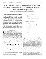
Roadmap Leads ITRS250•<strong>Technology</strong> Generation(nm)180130100907065•••TSMC′99 ITRS•♦′00 ITRS♦•′01 ITRS97 99 01 03 05 07 09Year
Gate Leakage Current
Gate Leakage Current
Subthreshold Leakage Current
Increased Gate Count
Increased Gate Count
<strong>Design</strong> Issues• Power• Signal Integrity• <strong>Design</strong> Complexity• System On Chip• Chip Packaging/Testing• Higher <strong>Design</strong> NRE
Power Issues• Increased DC power due to the leakage current and ACpower due to the higher clock frequency have made verydeep submicron technology designs become very expensive.<strong>The</strong> increased power dissipation demands expensivepackage.• Voltage island• Dual Vt optimization• Back bias technique• Power management• SOI• Strained semiconductor• <strong>Design</strong> complexity increased• New unknown materials
Power Issue
Multiple Vt Libraries for Leakage and SpeedOptimization• Multiple Vt design approach isrequired for reducing leakage current• Multiple Vt design is one of theimportant methods to design the deepsubmicron circuits in the powerconstrained era
<strong>Design</strong> Flow – LVtToHVtToLVt• Physical Compiler+ Power CompilerRTL <strong>Design</strong>Faster CellsHigh Leakage PowerLVt CellsG2PG Synthesis(Optimize timing with high speedcells for meeting the timingtarget first)Replace withHvt cells(Manually replace all LVt cells withcorresponding HVt cells)Define LeakageConstraintsset_switiching_acitivity –toggle_rate 0set_max_leakage_power 0set physopt_enable_power_optimization truSlower CellsLow Leakage PowerHVt CellsSwap LVt Cellsin critical paths(Minimize timing and powersimultaneously)physopt -timing_driven_congestion \-effort high -area_recoveryOptimizedNetlist
<strong>Design</strong> experiments with multi-Vt librariesPure LvtPure Hvt Approach A Approach BLvt Nvt Hvt Lvt Nvt Hvt Lvt Nvt Hvt Lvt Nvt HvtGates 79179 79179 32889 38617 24569 19121 29516Gates-total79179791797150673206SlackLeakage powerArea> 0 ns21.6 mW614461-3.49 ns1.28 mW6144610 ns5.76 mW4960370 ns5.0 mW434830• Three Vt‘s add one more dimension toperformance/power optimization• Leakage power can be saved• Silicon area is also improved
Signal Integrity• Lower supply voltage reduce noise margin• Smaller geometries induces coupling noise• Higher current density causes EM issues• Faster frequency worsen power/ground bouncing• Quick transient demands transmission line design• Extreme performance requires inductanceparasitic extraction
Signal Integrity• Sophisticated EDA tools must have• IR drop• Coupling noise• Inductance extraction• High speed I/O design• EM checking• Increased design complexity
Signal Integrity
Signal Integrity
Xtalk Prevention & Fixing FlowPCMax transition fixingfor xtalk preventionCmax .itf filesStar-RCCmax .grd filesStar-RCAstro XtalkGlobal Route&Track AssignmentPrevention&In-Route FixingPT-SIRepair Files withsizing & spacingfor delay fixingTiming windowfilesSpice Lib .cdBCelticRepair Files withsizing & spacingfor glitch fixingCmax .spef files(Prevention)AstroECO(Fixing)
<strong>Design</strong> <strong>Challenge</strong>s <strong>For</strong> <strong>Submicron</strong><strong>Technology</strong>• Low Supply Voltage• IR drop Power plan, Flip Chip• Special DFM rules• Double vias insertion• Dummy metal insertion and impact analysis• Process Variation• Interconnect process variation
Dummy vs. No Dummyx: path delay, y: path delay diff %
Power Planning & <strong>Design</strong>et Switching Activities fromVerilog SimulationGate-level NetlistSynopsys libraryIR-Drop &TSMC EM RulePower Estimation<strong>Design</strong> PowerInterconnect setload(Input From <strong>Design</strong>er)Power Consumption(including internal, switching& leakage power),Switching activityPower Width CalculationPower plan adjustmApollo/Astro P&R To quick convergeMultiple layers for P/G MeshInterleaving via arrayDecoupling cell insertionPower Grid AnalysisAstro-RailIR-Drop & EM Maps, ViasDFaPower Grid Sign-offVoltageStormOK
In-Die Variation Analysis Flowitf file with TSMC processvariation model<strong>Design</strong>grdgen(RC characterization)P&Rgrd file with processVariation informationMilkyway DataBaseStar RCXTSPEFRC with in-die process variationPT-SITiming Considering in-die process-variation
❖ RDL FlowFlip Chip Solutions• Silicon proven flow on several customer chips.❖ Area Array Flow• Cluster approach using TSMC developed flip chip IOs• Silicon validated on internal test chip.• Fine tuning for new IO cells (better structure)Area ArrayRDLESDIOIOIOIOIOIOESD
<strong>Design</strong> Complexity• Transistor number is doubled every 18month,soon, it will be 1 billion transistors• Clock frequency is increasing and approaching to2-5 GHz• Convergence of computer, communication andconsumer industries, meaning, mixed-mode designis inevitable• Increased mask cost demands complete andthorough verification before tape-out
<strong>Design</strong> Complexity• Engineering team coordination raises overheadfactor• Physical design does not scale• IP integration among different vendors• EDA tools have to address• Large capacity and efficient tools to handle large chip• Reduce physical design iteration• IP validation and integration tools• Standard IP interface architecture• Standard SOC platform architecture
<strong>Design</strong> Complexity
<strong>Design</strong> Complexity
<strong>Design</strong> Complexity
<strong>Design</strong> Complexity
<strong>Design</strong> Complexity
System On Chip• Except standard high performance CPUs andstandard memories, most of designs which needenter into very deep submicron technology shouldbe designed in the form of SOC to accommodatethe large count of transistor number andreasonable die size• Accountable and trustful IPs• Integration among different IPs• Architecture design becomes part of IC design
System On Chip• System design and RTL design gap• HW-SW co-verification• Software debug becomes part of IC designtapeout• System test vectors and RTL test vectorscompatibility issues• Verification complexity issues• EDA tools need to address• Early system design into part of IC design
System On Chip• SystemC for smooth architecture to RTL transition• HW-SW co-verification• Excellent IP portfolio• System and RTL test vectors convergence
System On Chip
Bluetooth ImplementationIP-Based <strong>Design</strong>DCXO PLLROMRAMLogicRADIOCPUFlash1-Port1-PortRAMRAM8Kx16x48Kx16x4ARM7ARM78-bit8-bitMCUMCUPlatform-based IP portfolio2-Port2-PortRAMRAM4Kx16x24Kx16x2CustomCustomLogicLogic100100MHzMHz8-bit8-bitDACDACMajor IP Building Blocks200200MHzMHzADCADC256x8256x8ROMROM8Kx168Kx16FlashFlashSpecialSpecialI/OI/OCPUCPUDSP IPMemory DSP IPMemoryIPIP SpecialSpecialMixed I/OMixed I/OSignal IPSignal IPRFRFSynthesizerSynthesizer2.52.5GHzGHzPLLPLL200200MHzMHzPLLPLL
SoftwareMain ( ) {ao=ao+r1+rz;ao=ao=*r1ao=ao+a1if(gt) goto overao=ao-1;overSoftwareMain ( ) {int I, j, k,I=z;j=o;loop:k=j*I+23;j=k-j;Library Links SoC and <strong>Technology</strong>System SystemSpecification SpecificationDSPMCUAnalogASIC<strong>Design</strong>GenerationVerification VerificationLibrariesLibrariesStd. Cell & I/OLPSCDevicesMemoriesAnalogCores<strong>Technology</strong>• <strong>Design</strong> is getting morecomplex• <strong>Technology</strong> too• Library is the key linkPhysicalDeviceDescriptionAnalogCMOSTransistors3.3VCMOSDevicesProgrammableLogicSi, SiGeBipolarDeviceRFPassivesPLATFORMCMOSCOREFlashMemoryHi-DensityRAM W/BISTFast GateCMOSDevicesCopperWiringPrecisionCapacitorM.R. Pinto, “Atoms to Applets: Building Systems Ics in the 21st Century,” ISSCC2000, pp. 26- 30.
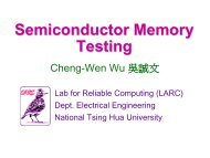
Chip Packaging/Testing• Need to perform complex testing due to theenormous transistor count and functions• <strong>Design</strong> for testability might be mandatoryrequired• At-speed test becomes difficulty due to thehigher clock rate• Logic BIST can perform at-speed functional testat the expense of silicon area and designcomplexity
Chip Packaging/Testing• SOC testing challenges the test vendors tocombine logic, memory and analog testing in thereasonable price and time• EDA tools need to address following• Sophisticated logic BIST tools for at-speed test• <strong>Design</strong> for testability• Scan test and memory BIST might be mandatoryrequired• Test vendors need to provide cheap and efficient testmachine for SOC designs
Increased Packaging Complexity
Increased Packaging Complexity
Increased Packaging Complexity
Higher <strong>Design</strong> NRE• <strong>Design</strong> NRE is soaring up to tens of Millions• Basically, it is summed up by engineers’ manhours, engineers’ productivity, tools usage,design equipments, software development, systemverification and IPs’ license fees• High NRE might limit silicon re-spins• Limited re-spins might extend the design timelength which will increase the design cost• Re-programmable mask design methodology mightbe required
Higher <strong>Design</strong> NRE• <strong>Design</strong> methodology need to address• Early and efficient prototyping for verification• Reprogrammable SOC products
Higher <strong>Design</strong> NRE