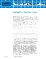
WELDING<strong>HAYNES</strong> <strong>188</strong> <strong>alloy</strong> is readi ywelded by Gas Tungsten Arc(TIG), Gas Metal Arc (MIG),Shie ded Metal Arc (coatedelectrodes), electron beamwelding and resistance weldingtechniques. Its welding characteristics are similar to those for<strong>HAYNES</strong> 25 <strong>alloy</strong>. SubmergedArc welding is not recommended as this process ischaracterized by high heatinput to the base metal andslow cooIng of the weld. Thesefactors can ncrease weldrestraint and promote cracking.Base Metal PreparationThe joint surface and adjacentarea should be thoroughlycleaned before welding. Allgrease, oil, crayon marks, sulfur compounds and otherforeign matter should beremoved. Contact with copperor copper-bearing materials inthe joint area should beavoided. It is preferable, butnot necessary, that the <strong>alloy</strong> bein the solution-annealed condition when welded.Filler Metal SelectionMatching composition fillermetal is recommended for joining <strong>188</strong> <strong>alloy</strong>. For joiningsection thicknesses greaterthan 3/8 in. (9.5 mm) 230~Wwfiller wire is suggested. Forshielded metal arc welding,<strong>HAYNES</strong> 25 <strong>alloy</strong> electrodes(AMS 5796) are suggested. Fordissimilar metal joining of <strong>188</strong><strong>alloy</strong> to nickel-, cobalt- or ironbasematerials, <strong>188</strong> <strong>alloy</strong> itself,230-W filler wire, 556TM <strong>alloy</strong>,HASTELLOY S <strong>alloy</strong> (AMS5838) or HASTELLOY W <strong>alloy</strong>(AMS 5786, 5787) weldingproducts are suggested,depending upon the particularcase.Preheating, InterpassTemperatures and Post-WeldHeat TreatmentPreheat is not usually requiredso ong as base meta to bewelded is above 32 F (0°C).Interpass temperatures generally should be low. Auxiliarycooling methods may be usedbetween weld passes, asneeded, prov d ng that suchmethods do not introduce contaminants. Post-weld heattreatment is not normal yrequired for <strong>188</strong> <strong>alloy</strong>. For further information, please contact<strong>Haynes</strong> <strong>International</strong>.HEALTH AND SAFETY INERMATIONWelding can be a safe occupation. Those in the weldingindustry, however, should beaware of the potential hazardsassociated with welding fumes,gases, radiation, electricshock, heat, eye injuries, burns,etc. Also, local, municipal,state, and federal regulations(such as those issued byOSHA) relative to weldng andcutting processes should beconsidered.Nickel-, cobalt-, and iron-base<strong>alloy</strong> products may contain, invarying concentrations, the following elemental constituents:auminum, cobalt, chromium,copper, iron, manganese,molybdenum, nickel and tungsten For specificconcentrations of these andother elements present, refer tothe Materal Safety Data Sheets(MSDS) H3095 and H1072 forthe product.Inha ation of metal dust orfumes generated from weldng,cutting, grind ng, melting, ordross handling of these <strong>alloy</strong>smay cause adverse healtheffects such as reduced lungfunction, nasal and mucousmembrane irritation. Exposureto dust or fumes which may begenerated in working withthese <strong>alloy</strong>s may alsocause eye irritation, skin rashand effects on other organsystems.The operation and maintenance of welding and cuttingequipment should conform tothe provisions of AmericanNat onal Standard ANSI/AWSZ491, (Safely in Welding andCuffing”) Attention s especia y cal ed to Section 7(Protect on of Personnel) and 8(Heath Protect on andVentilat on) of ANSI/AWS Z491.Mechanical ventilation s advisable and, under certainconditions such as a very confined space, is necessaryduring welding or cuffing operations, or both, to preventpossible exposure to hazardous fumes, gases, or dustthat may occur.<strong>HAYNES</strong> <strong>188</strong> <strong>alloy</strong>
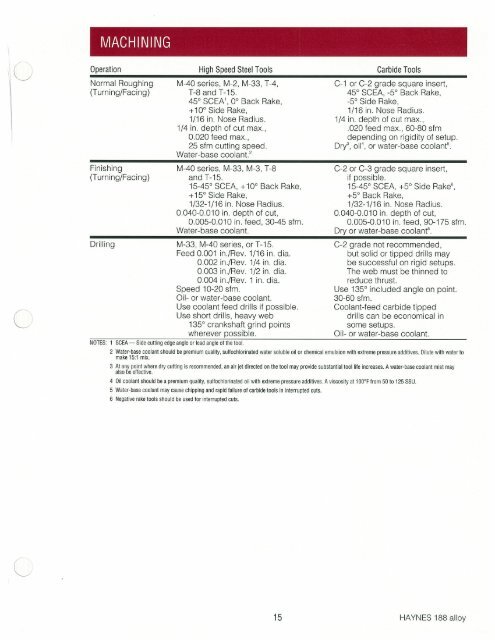
MACH NINGOperation High Speed Steel Tools Carbide ToolsNormal Roughing M-40 series, M-2, M-33, T-4, C-i or C 2 grade square insert,(Turning/Facing) T-8 and T-15. 45 SCEA, -5 Back Rake,450 SCEA’, 0° Back Rake, -5° Side Rake,+10° Side Rake, 1/16 in. Nose Radius.1/16 in. Nose Radius. 1/4 in. depth of cut max.,1/4 in. depth of cut max., .020 feed max., 60-80 sfm0.020 feed max., depending on rigidity of setup25 sfm cutting speed. Dry3, oil4, or water-base coo ant.Water base coolant.F nish ng M-40 series, M-33, M-3, T-8 0-2 or 0-3 grade square insert,(Turning/Facing) and T-15. if possible.15-45° SCEA, +10° Back Rake, 15-45° SCEA, +5° Side Rake,+15~ Side Rake, +5 Back Rake,1/32-1/16 in. Nose Radius. 1/32-1/16 in. Nose Rad us.0.040-0.010 in. depth of cut, 0.040-0.010 in. depth of cut,Water-base coolant.DrillingM-33, M-40 series, or T-15.Peed 0.001 in/Rev. 1/16 in. dia.0.002 in./Rev. 1/4 in. dia.0.003 in/Rev. 1/2 in. da.0.004 in/Rev. 1 in. d a.Speed 10-20 sfm.Oil or water-base coolant.Use coolant feed drills if p055 ble.Use short drills, heavy web135° crankshaft grind pointswherever possible.NOTES: 1 SCEA — side cutting edge angle or lead angle of the tool.Dry or water-base coolant.C-2 grade not recommended,but solid or tipped dr Is maybe successful on rigid setups.The web must be thinned toreduce thrust.Use 135° included angle on point.30-60 sfm.Coolant-feed carbide tippeddrills can be economical insome setups.Q~ - or water-base coolant.2 Water-base coolant should be premium quality, sulfochiorinated water soluble oil or chemical emulsion with extreme pressure additives. Dilute with water tomake 15:1 mix.3 At any point where dry cutting is recommended, an air let directed on the tool may provide substantial tool life increases. A water-base coolant mist mayalso be effective.4 Oil coolant should be a premium quality, sulfochiorinated oil with extreme pressure additives. A viscosity at 1 006F from 50 to 125 ssu5 Water4ase coolant may cause chipping and rapid failure of carbide tools in interrupted cuts.6 Negative rake tools should be used for interrupted cuts.<strong>HAYNES</strong> <strong>188</strong> <strong>alloy</strong>